http://www.sciencepublishinggroup.com/j/ijsqa doi: 10.11648/j.ijsqa.20190501.15
ISSN: 2469-8156 (Print); ISSN: 2469-8164 (Online)
A Combined Algorithm for Noisy Whole-body Bone Scan
Image Enhancement
Sulieman Mohammed Salih Zobly
Department of Medical Physics & Instrumentation/National Cancer Institute, University of Gezira, WadMedani, Sudan
Email address:
To cite this article:
Sulieman Mohammed Salih Zobly. A Combined Algorithm for Noisy Whole-body Bone Scan Image Enhancement. International Journal of Science and Qualitative Analysis. Vol. 5, No. 1, 2019, pp. 29-35. doi: 10.11648/j.ijsqa.20190501.15
Received: May 6, 2019; Accepted: June 12, 2019; Published: June 29, 2019
Abstract:
A bone scan is one of the most important diagnoses done using a gamma camera in nuclear medicine for detecting bone problems, such as cancer lesion, to find out if the cancers spread to the bones besides finding out how the metastases respond to chemotherapy and radiotherapy treatment. Generally nuclear medicine images degraded by a large amount of noise, which is effecting on the resulting image. In this work we work we want to propose a combined enhancement algorithm based on fast Fourier transform and Sobel, for metastases whole-body bone scan image enhancement, to reduce the image noise, increase the image quality for better viewing and assist the nuclear medicine physician diagnosing images effectively. The proposed algorithm compared with existing enhancement algorithms such as histogram equalization, adaptive histogram equalization, log transformation and gamma correction. The algorithm applied to seven patients with bone metastases. It turns out that the proposed algorithm can help to improve the quality and visualization of the images. Our simulations show that the proposed algorithm removes the noise without significant blurring the structure of the image, increase the image quality and gives clear legions. The algorithms evaluated by calculating PSNR and RMSE. The proposed algorithm gives higher PSNR and lower RMSE.Keywords:
Gamma Camera, Nuclear Medicine, Image Enhancement, Spatial Enhancement, Fast Fourier Transform1. Introduction
Image processing is one of the most important technique find attention is a few years ago, because of its vast application in industry, robots, satellites and medical applications [1]. There are many enhancement algorithms proposed for image enhancement such as histogram equalization, adaptive histogram, log transformation, gamma correction, etc. [2 - 7]. Most of enhancement algorithms used to improve image visualization or to provide a better representation for the image features by improving the contrast, brightness and sharpness of the images.
Image enhancement categorized into two main categories: frequency domain and spatial domain [8]. Spatial domain in image processing refers to the image plane itself, and this process based on direct manipulation of an image pixel. The spatial domain process denoted by the expression
g x, y T f x, y (1)
Where f x, y is the input image, g x, y is the processed image and T is the operator on f defined over some neighborhood of x, y . As well, T can operate on a set of input images for noise reduction.
Frequency domain process refers to techniques that modify the Fourier transform of an image. Image enhancement based on Fourier transforms concerned primarily with the properties of spectrum and power spectrum. The power spectrum defined as the square of the Fourier spectrum.
F u R u I u / (2) P u |F u | = R u I u (3) Where, R u is the real part and I u is the imaginary part. The bone scan imaging performs within a few minutes, un-expensive and widely available. During the whole-body bone scan with a gamma camera, the scan takes image of all bones starting from the head to the toe for the patient with skeletal pain [9-11].
injected into the patient’s arm or hand. The blood needs 2-3 hours to take the tracer to all bones in the body, some excrete in urine, and then the patient moved into the camera for imaging, the imaging takes about 20 - 35 min [12 - 14]. Information’s obtained from bone scan in nuclear medicine are more related to the physiological function of the body opposed to that obtained by X-ray systems. Therefore, with bone scan different prospective and information can be obtained, and help the physician in diagnosing the patient effectively. But the resulting images degraded with the noise because of limited number counts and scatter of photon or attenuation. Hence, it is crucial to improve the image quality by enhancing the resulting bone scan image in order to show more details or lesions that help diagnose the patient properly.
In image enhancement, the algorithm that is quite useful for enhancing the image of such application such as X-ray image may not essentially be the best approach for enhancing an image from another modality such as Brest image, thus adaptive and combine algorithm was the best solution for enhancing different modalities.
In this work, we proposed a combined algorithm for bone scan image enhancement by integrating spatial enhancement with fast Fourier transformation in order to remove the noise from the images and assist the physician in diagnosing the abnormality effectively. We aim to improve the intensity of bone scan image and maintain the visualization of abnormality. We have compared our proposed algorithm with four existing enhancement methods and evaluate the resulting images using three performance measures.
The rest of paper organized as follows in section II the material and methods used in this work were discussed in details beside the performance measure algorithms used to evaluate the proposed algorithm. The enhanced image using present algorithms and our proposed algorithm was presented in section III. In the last section the conclusion of the work presented.
2. Methods
In this section we will discuss the performed bone scan image, common enhancement methods used for image quality improvement, the proposed method and the methods used for measuring the enhanced image performance.
2.1. Bone Scan Image
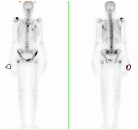
The bone scan image was acquired using dual head SPECT gamma camera (Mediso DHV- Nucline camera) 2-3 hour after injection the patient with radiopharmaceutical (Tc-99m) and resolution 256 x 1024 pixels with 16 bit grayscale. Seven pairs of bone scan images obtained from seven patients with bone metastases, in which each included anterior and posterior views obtained from two heads of gamma camera facing each other.
Figure 1 shows Anterior and posterior images for one patient with bone metastases
Figure 1. Bone scans image, anterior image left and posterior image right.
2.2. Image Enhancement in Spatial Domain
In image processing it’s very important to improve the image quality, so that the result image is more suitable than the original one, for a specific application. In image enhancement, algorithms suit for specific application cant suit for another, thus different approaches can be used for specific image quality improvement [8, 15 - 18]. The approach based on direct pixel manipulation of the image known as spatial domain, which is denoted by the expression.
g(x. y) = T[f(x, y)] (4) Where g(x, y) represents the modified image, T is an operator applied at each location (x, y) in an input image f(x, y). In this section only the transform functions that can be used for enhancing a wide dynamic range image can be discussed.
The simplest form of transforming function when a neighborhood is of size 1 x 1 in this case the output depend only on the value of the input image at (x, y) and the transform operator becomes a gray-level or known as intensity. 1 x 1 neighborhood is called a point processing and it’s represented by s = T(r) where s and r represent the intensity of the output and input image respectively. The neighborhood function size can be larger 9 x 9, which is given more flexibility.
Negative transformation can be obtained from the gray-level in the range of [0, L-1], this phenomena known as image negative and it is given by expression s = L-1-r. This type of processing used commonly for enhancing white or gray details in the dark regions of an image such as enhancing breast image from digital mammography.
Higher intercity can be reduced by using log transforms, which is mapped a higher range of high intensity input level to a narrow range of output levels or the opposite. This type of transform used to expand the values of dark pixel in an image [7]. The log transforms expressed as:
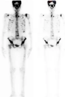
Where, c is constant and assumed r ≥ 0. Figure 2 show an image enhanced with log transform. The result shows that some important details of skeletal have been removed because of the high gray level in some part and low gray level in other parts of the image.
Figure 2. Original bone scan image left side & enhanced image with log transform right side.
The most common contrast enhancement methods used for noise reduction and image visualization enhancement in medical imaging is power law transformation, which is mapped to a higher range of dark input values to narrow the range of output values with the opposite being true for the narrow values of input. Due to the exponent in the power law equation this known as gamma correction [8]. If the constant c = 1 the quality of the result image depend on the gamma values γ. The suitable gamma value can give image with high quality [6]. This transforms expressed as:
(6) Where c and γ are positive constant
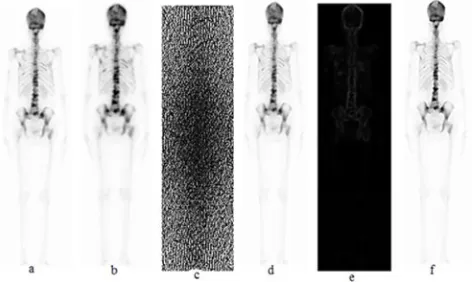
Power law transformation is useful for contrast manipulation; the result image depends on the gamma values as shown in figure 3. The figure show bone scan image processed with the power law contrast function equation (6). The gamma values used corresponding to images (b) through (f) are 0.3, 0.6, 0.7, 2, and 3.
Figure 3. (a) Original bone scan image (b) enhanced image with γ=0.3 (c)
enhanced image with γ=0.6 (d) enhanced image with γ=0.7( e) enhanced image with γ=2 (f) enhanced image with γ=3
We note that gamma values decreased from 0.7 to 0.5 more details become visible. Decreasing the gamma values more to 0.4 a little detail of the image will be enhanced in the background and the gamma values more than 2 gives a noisy image [6].
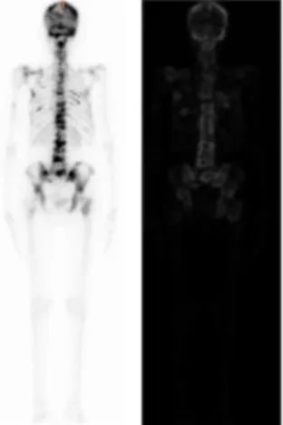
In the gray level, the dynamic range can be increased by stretching the contrast of the image need to be enhanced, besides the possibility of highlighting a specific range of gray levels in the desired image to enhance some specific features. The ranging and highlighting the range of the gray level doesn’t fit with bone scan image because of a very wide dynamic range in the image. Figure 4 (a) shows bone scan image enhanced with histogram equalization (HE) (b) and adaptive histogram (AHE) (c). The result shows that both algorithms give noisy image and unclear legions.
Figure 4. (a) Original bone scan image, (b) Image enhanced with HE, (c) Image enhanced with AHE.
In spatial domain there are some filtering techniques performed directly on the pixels of an image, these techniques known as spatial filtering. The techniques of spatial filtering consist of a mask which is moving from point to point in an image. The response of the filter is calculated at each point using predefined relationship. Many filters have been developed and used such as smoothing filter, which is used for blurring and noise reduction, and sharpening filter, which is used to highlight fine detail or to enhance details that have been blurred [8]. Sharpening technique can be used in bone scan image to enhance the image and bring out more details. The most common methods used for edge detection was Sobel operator, which is performed by using masks.
region. This increases the edge intensity and it’s become enhanced compared to the original image. Figure 5 illustrates the bone scan image enhanced with Sobel operator. The result
shows that the operator highlights all the borders of the metastasis in the image, but at the same time most of the image details degraded.
Figure 5. Left original bone scan image, right image enhanced with Sobel operator.
2.3. Image Enhanced in Frequency Domain
Image enhancement based on frequency domain based on modifying the transform function of an image via filtering function, then take the inverse of the result to obtain the modified image. The basic steps of enhancing an image in the frequency domain illustrated in figure 6.
Figure 6. The basic steps of image enhancement in frequency domain
The Fourier transform of the output image is given by: G(u, v) = H(u, v)F(u, v) (7) H(u, v) is the filter transfer function and the multiplication of F and H based on multiplying element by element. The first element in F multiplied by the first element in H and the second element multiplied by the second element and so on. The final image obtained by calculating the inverse Fourier transforms.
2.4. Proposed Algorithm
The narrow dynamic range of the gray level and the high noise content make bone scan image difficult to enhance. Thus
we intend to develop and enhancement algorithm, which is enhancing the bone scan image by reducing the noise and sharpening the hot area (lesion), can improve the quality of the images for human viewing. As discussed in previous sections all enhancement algorithms used cant enhanced this type of image, thus to achieve the desired image a combine different enhancement algorithm needed. The steps of the proposed algorithm are summarized as follows.
Step 1: Let the input image I intensity values represented by f(x,y)
Step 3: Apply Fourier transforms to the result image from step 2, the output image was II.
Step 4: Apply Sobel algorithm to the result image from step 2, the output image was III.
Step 5: Convolve the result images from step 3 and 4; the resulting image was convolved image V.
Step 6: the result image from step 5 summed with the prepossessed image from step 2, the resulting image of this process was VI.
Step 7: The resulting images from steps 5 & 6 are convolved together and then convolved the result image with the image from step 3. The result image summed with the resulting image from step 2 to get the sharpened image which is represented the final proposed image VII.
The proposed algorithm evaluated by using qualitative and quantitative evaluation methods. The quantitative performance measures used are root mean square error (RMSE), and peak signal-to-noise ratio (PSNR).
The RMSE represents the amount of changes between the original image pixels and the corresponding recovered image pixels using the following equation:
RMSE ∑ ∑'& %& I i, j $ II i, j (8)
Where, I(i, j) and II(i, j) are the pixel intensity of the original and recovered image respectively and m, n are the size of an image.
The RMSE measurement is easily computed by taking the square root of the average squared difference between every pixel in the original image and the recovered image.
Peak signal-to-noise ratio (PSNR) is one of the useful performance measures, which represents the ratio between the maximum power of an image and the power of computing noise that affect the image representation. PSNR used to estimate the quality of the image after pre and post processing, the image with a high PSNR value was the best. PSNR measure in Decibel dB and calculated as follows:
()*+ 20 log 0 255/+2)3 dB (9)
3. Result and Discussion
In this section we will show the performance of our proposed algorithm on a real bone scan images. The result of the proposed technique compared to the existing state-of-art image enhancement techniques, namely histogram equalization [2], adaptive histogram equalization [7], log transformation [8] and gamma correction [9]. The comparison has been performed in both qualitative and quantitative manner. To evaluate the proposed algorithm real bone scan images are considered.
To evaluate the images quantitatively RMSE, PSNR and entropy performance measures were used.
To a chive the desired enhanced image with the proposed method some steps followed, the results of the steps are shown in figure 7.
Figure 7. The result images from the steps followed to achieve the proposed
algorithm, (a) original image, (b) the result image from prepossessed (c) the result image from Fourier transform, (d) the result image from convolution, (e) the result image from masking and (f) the result image from the proposed algorithm.
Figure 7a shows the original bone metastases image, the original image prepossessed to be ready for the next step for enhancement, the result image shown in figure 7b. Figure 7c shows the Fourier transform of the enhanced image. Convolved image shown in figure 7d. Figure 7e shows the masked image and figure 7f. shows the enhanced image with the proposed algorithm.
The selected sample images with bone metastases enhanced with the proposed and existing methods are shown in figure 8.
Figure 8. Image enhanced with; (a) HE, (b) AHE, (c) gamma correction, (d)
log transform and (e) proposed algorithm.
The resulting images were evaluated using RMSE, and PSNR. Figure 9 shows the result of PSNR for different enhancement algorithms. From the result AHE gives a lower PNSR value which is mean that the quality of the image was the worst among all the algorithms used. The proposed algorithm gives highest PSNR value among others algorithms used for this work. Log transform algorithm gives image with good quality but lower than the proposed algorithm.
Figure 9. PNSR for reconstructed images with different algorithm
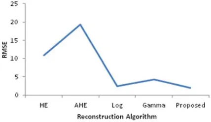
Figure 10 shows the RMSE calculated from enhanced images using different algorithms. The figure shows that our proposed algorithm gives lower RMSE and AHE gives higher value. Log transform and gamma correction algorithm values are lower than HE algorithm.
Figure 10. RMSE for reconstructed images with different algorithms
We can conclude that our proposed algorithm can enhance the bone scan image and gives the highest quality image besides showing all the fine details of the image compare to the other enhancement techniques.
Table 1 shows the result of performance evaluation for different algorithms, from the table; it's clear that adaptive histogram equalization gives the worst image because of its lower PSNR 22.35. The highest PSNR was 41.32 potent from image enhanced with our proposed algorithm, this mean that our proposed algorithm gives best result among all algorithms. The RMSE also was calculated from all the algorithms the result shows that AHE image gives highest value 19.43 and the proposed algorithm gives lowest value 2.03, which is mean the image enhanced with our proposed algorithm was the best. The image enhanced with log transform gives lower RMSE than
that from image enhanced with gamma correction.
Table 1. PSNR & RMSE calculated from all algorithms.
Algorithm PSNR RMSE
HE 27.41 10.87
AHE 22.35 19.43
Log transform 40.22 2.48
Gamma correction 35.43 4.31
Proposed algorithm 41.32 2.03
4. Conclusion
This research compares the most common image enhancement algorithm with a new proposed enhancement algorithm based on combining Fourier transform and Sobel enhancement algorithms to enhance metastasis bone scan images. Existing methods can enhance the bone images but some blurs the images and others remove some fine details of the images, which is effected on the resulting images. To evaluate the effectiveness of illustrated methods RMSE and PSNR was used. These parameters show that how the results vary when applying different techniques of enhancement to the metastasis bone scan images. The result shows that our proposed method gives better image by giving higher PSNR 41.32 and AHE gives the lowest PSNR value 22.36, enhanced image with AHE was the worst image. Log transform can give image with good quality but some details will be removed beside PSNR for this algorithm lower than the proposed methods. The proposed methods give lower RMSE among all the techniques used, RMSE from the proposed methods was 2.02 and the highest one was 19.44 from AHE technique. The proposed algorithm shows significant performance as compared to other enhancement techniques. bone scan images enhanced with our proposed algorithm shows clearer legion, noise free image and very effective during patient diagnosis.
References
[1] G. Palanisamy and A. Samukutti, “A Novel Embedded Set Partitioning Significant and Zero Block Coding,” The International Arab Journal of Information Technology, vol. 5 (2), pp. 132- 139, 2008.
[2] T. Kim et al., Image enhancement using histogram equalization, SIP/WSE, pp. 17-24, 2012.
[3] A. Das, Guide to Signals and Patterns in Image Processing Foundation, Methods and Applications, Springer International Publishing Switzerland 2015.
[4] W. Yang et al., Signals and Systems with MATLAB, Springer, 2009.
[5] E. Irmak, A. Ertas, A review of robust image enhancement algorithms and their applications, Smart Energy Grid Engineering IEEE conference, 2016.
[7] S. Zobly M. Abdelrhmanm Whole-body bone scan image enhancement algorithms, International Conference on Computer, Control, Electrical and Electronic Engineering 2018.
[8] R. Gonzalez, R. Woods, Digital Image Processing, 3rd edition, Pearson Education, In., 2009.
[9] C. Love, et al, Radionuclide bone imaging: An Illustrative review, Radio Graphics, vol. 23(2), pp. 341-358, 2003. [10] A. Lagaru, R. Minamimoto, Nuclear Medicine Imaging
Techniques for Detection of Skeletal Metastases in Breast Cancer, PubMed, vol. 13(3):383-393, 2018.
[11] W. Noordzij, A. Glaudemans, Nuclear Medicine Imaging Techniques. In: A. Glaudemans, et al. Nuclear Medicine and Radiologic Imaging in Sports Injuries, Springer, Berlin, Heidelberg.
[12] M. Connor, et al, The Art of bone Scintigraphy-technical aspect, J Nucl Med, vol. 32, pp. 2332-2341.
[13] E. Kim, et al. Handbook of Nuclear Medicine and Molecular Imaging: Principles and Clinical Applications, Cdr edition, World Scientific Publishing Company, 2012.
[14] FD Rollo. Molecular imaging: an overview and clinical applications, Radiol Manage, vol. 25(3):28-32, 2003.
[15] Geoff Dougherty, digital image processing for medical application, Cambridge University Press United State, New York, 2009, ISBN: 978-0-521-86085-7.
[16] V. Ponomaryov, et al., Image and video quality improvement techniques for emerging applications, EURASIP J. Adv. Signal Process 2012.
[17] M. Takezawa et al., Quality improvement technique for JPEG images with fractal image coding, IEEE International Symposium on Circuits and Systems 2005.