Linear Programming Problem for
Optimum Coordination of Overcurrent
Relays
Tushar Shingala, Vasav Shethna Student
Department of Electrical Engineering, Nirma University
Ahmedabad, India
[email protected], [email protected] S. S. Kanojia
Assistant Professor
Department of Electrical Engineering, Nirma University
Ahmedabad, India [email protected]
Abstract:
Coordination among protective devices is essential in power systems so that it improves security and reliability. Overcurrent relays are widely used in such systems. Overcurrent relays not only provide primary but also act as backup protection to electrical distribution system. The relays have to be coordinated and set at the near optimum values, ensuring that least damage occurs when there is a fault. The main purpose of coordination is to find an optimum relay setting that will minimize the total time of operation of relays, preventing false operation of relays. A ring distribution system is simulated in ETAP in the paper. Optimum coordination between primary and backup relay for standard 9 bus system is obtained using Linear Programming Problem Dual Simplex Method in MATLAB and the same has been simulated in ETAP.
Key words- Linear Programming Problem, Optimum relay coordination, IEEE 9-bus system, Dual simplex method.
1. Introduction
For providing protection in distribution systems, overcurrent relays are commonly used because of their simple operation and relatively easiness in coordination. The common distribution system is radial in nature, i.e. power flows in one direction from source to load. Usually, distribution systems are protected by inverse definite minimum time (IDMT) overcurrent and earth fault relays.
When fault occurs at a particular location in a system relay of that zone should operate first as a primary protection. In case it fails to operate, backup protection is provided by near-by zone relay. Hence primary and backup relay should be well coordinated, whereas malfunction could lead to failure of power system.
In a system where there is more than one source, fault current can flow in any direction. Usage of non-directional overcurrent relays needs proper coordination with relays at the remote end and relays behind them. Directional relays prevents coordination with the relays next to them as they operate in a specific direction on occurrence of fault. While designing protection scheme for distribution system, we need to calculate PSM and time dial setting (TDS) for overcurrent relays used in system.
Coordination problem of overcurrent relay can be defined as constrained optimization problem. Solution for the same can be found using dual simplex algorithm of Linear Programming Problem (LPP). In this method, as additional variables are not needed so computation time required is less.
So the main purpose of this paper is to get the optimum coordination of overcurrent relays for given 9-bus system using Dual Simplex Method of Linear Programming Problem.
2. Coordination of overcurrent relays in IEEE 9-bus system
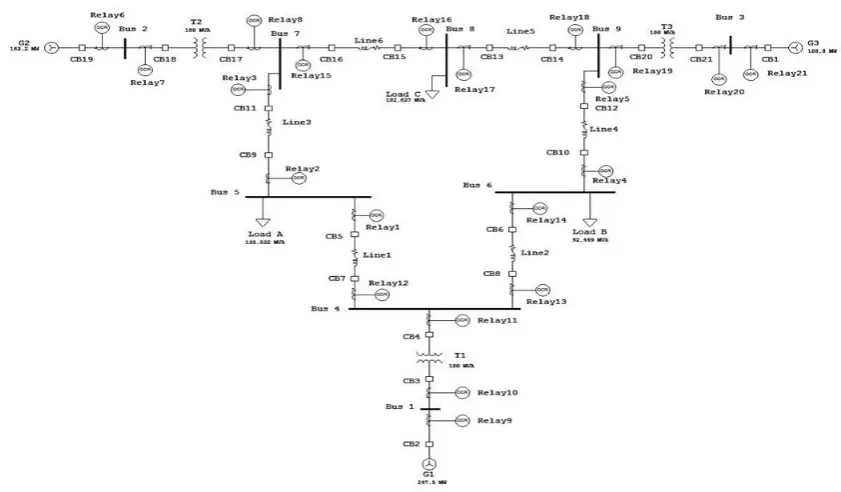
Fig. 1 shows 9 bus system that consists of 3 number of generators, 3 transformers, 6 transmission lines, 3 loads, 9 buses and 12 relays and circuit breakers combination. If a fault occurs at any place then the relay having least TDS and nearer to fault location should operate. If somehow primary relay fails to operate then the relay having TDS greater than former one should operate. Even if latter fails then this sequence should continue upto the generator side.
Suppose a fault occurs on generator bus then the circuit breaker nearer to generator bus should trip first, because there is high current during a fault on generator side. So the generator bus relay has to give tripping signal as soon as the fault occurs. In case of failure then tremendous amount of current would flow through the system that can cause system to collapse if the case not handled properly.
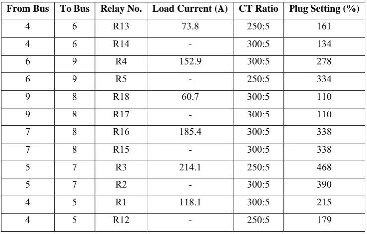
Standard IEEE 9-bus system is simulated in ETAP software and based on load flow analysis we found out the CT ratio and plug setting which is given in following table 1 for all 12 relays
Table 1. Plug Setting and CT ratio of 9 bus system
From Bus To Bus Relay No. Load Current (A) CT Ratio Plug Setting (%)
4 6 R13 73.8 250:5 161
4 6 R14 - 300:5 134
6 9 R4 152.9 300:5 278
6 9 R5 - 250:5 334
9 8 R18 60.7 300:5 110
9 8 R17 - 300:5 110
7 8 R16 185.4 300:5 338
7 8 R15 - 300:5 338
5 7 R3 214.1 250:5 468
5 7 R2 - 300:5 390
4 5 R1 118.1 300:5 215
4 5 R12 - 250:5 179
Fig. 1. Standard IEEE 9 bus system with overcurrent relay protection scheme
3. Problem Formulation
Linear programming problem is a mathematical optimization technique used to solve linear problems. An objective function and constraints can be given as
min = ( )
∗ ≤
∗ =
≤ ≤
Where, = Relay operating time for primary and backup relays, , = TDS of relays,
= Operating time of relay, = Coordination Time Interval,
, = lower and upper boundaries for TDS,
∗ ≤ Can also be represented as − ∗ − .
3.1.Main purpose here is to minimize the objective function which is given as
f = [ ∗ ∗ ∗ ∗ ∗ ∗ ∗ ∗ ∗ ∗ ∗
∗ ]
(1) 3.2.When a fault occurs at that time for the protection of the system, following constraint must be satisfied
= time of operation of primary relay for TDS = 1
= Coordination time interval for protection 3.3.Boundary points for relay operating time
− ≤ −0.5 − ≤ −0.5
− ≤ −0.5 − ≤ −0.5
− ≤ −0.5 − ≤ −0.5
− ≤ −0.5 − ≤ −0.5
− ≤ −0.5 − ≤ −0.5
− ≤ −0.5 − ≤ −0.5
0.05 ≤ ≤ 1.1
=
( ( ) )(4) Where, = relay operating time
TMS = Time Multiplier Setting PSM = Plug Setting Multiplier For normal IDMT relay, the value of is 0.14 and is 0.02.
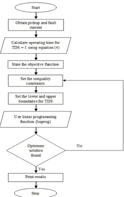
4. Flowchart For Optimization
Protective scheme optimization starts with load flow analysis and fault analysis and from that we can find out pickup current and fault current for the relays. Using equation (4) we can find out operating time of each relay as primary protection to nearby faults and as backup protection to far end faults.
From calculated values of operating time we can form objective function and inequality constraints. Set the boundaries for TDS and then use the linear programming function of MATLAB.
The flowchart to obtain optimized value of TDS of relay is shown in fig. 2 below.
Fig. 2. Flowchart for TDS optimization
5. Results
If exit flag in linear programming of MATLAB results to 1 then it represents that the given function is converged to optimized value, else given function is not optimized. Using Linear Programming Problem in MATLAB, the following results are obtained.
The values of TDS obtained from MATLAB are given in Table 2
Table 2. Optimized TDS value of Relay
Sr. No. Relay No.
Optimized TDS value
1 13 0.392
2 14 0.341
3 4 0.322
4 5 0.476
5 18 0.423
6 17 0.235
7 16 0.250
8 15 0.439
9 3 0.337
10 2 0.225
11 1 0.342
Table 3 below shows the primary and backup relay time dial setting and operating time.
Table 3. Optimized Backup Protection System
Primary Relay No. TDS Operating Time (s) Backup Relay No. TDS Operating Time (s)
12 0.337 0.670 14 0.341 1.078
13 0.392 0.780 1 0.342 0.924
1 0.342 0.161 3 0.337 1.170
2 0.225 0.627 12 0.337 0.670
14 0.341 0.766 5 0.476 1.989
4 0.322 0.780 13 0.392 0.787
15 0.439 0.713 2 0.225 0.970
3 0.337 0.830 16 0.250 0.900
17 0.235 0.467 15 0.439 1.262
16 0.250 0.724 18 0.423 0.841
18 0.423 0.841 4 0.322 0.885
5 0.476 0.100 17 0.235 0.526
The overall minimized value of the function mentioned in equation (1) is 13.1050
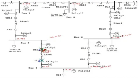
Fig. 3 shows operation of breaker when there is Line to Ground fault on line 1. It explains that which breakers would operate in sequence in order to protect the system.
For e.g. when fault occurs on line 1 then Relay 1 and Relay 2 would operate and give tripping signal to breakers. Hence line 1 will get isolated from the system and thus protecting the system.
Fig. 3. Operation of breakers during fault on line 1
6. Conclusion
From the above results, we conclude that the optimized value of TDS of relays have been obtained for standard IEEE 9-bus system using dual simplex method of Linear Programming Problem.
REFERENCES
[1] Bedekar, Prasant P., Sudhir R. Bhide, and Vijay S.Kale. "Coordination of Overcurrent Relays in Distribution System using Linear Programming Technique." International Conference on Control Automation Communication and Energy Conservation. Kongu
Engineering College, Erode, 2009.
[2] Bedekar, Prasant P., Sudhir R. Bhide, and Vijay S.Kale. "Optimum coordination of overcurrent relays in distribution system using dual simplex method." Second International Conference on Emerging trends in Engineering and Technology. 2009.
[3] Bedekar, Prashant P., Sudhir R. Bhide, and Vijay S. Kale. "Optimum coordination of overcurrent relays in distribution system using genetic algorithm." Third International Conference on Power Systems. Kharagpur, India, 2009.
[4] Bhajla, Bhavesh, R.P. Maheshwari, and Nilesh G. Chothani. "Protection and Switchgear." Oxford University Press, India, 2011. [5] Ram, Badri, and and Vishwakarma D. N. Power System Protection and Switchgear.New Delhi: Tata McGraw Hill Publishing
Company Limited, 2008.
[6] S.S., Rao. “Engineering optimization – theory and practice, third edition,”.New Delhi: New Age International (P) Limited, Publisher,
1998.
[7] Urdaneta A.J., Nadira Ramon, and Luis G.P. Jimenez. "Optimal Coordination of Directional Relays in Interconnected Power System."
IEEE Trans. on Power Delivery, Vol 3, No. 3 (IEEE Trans. on Power Delivery), July 1988: pp. 903-911.
[8] S. Ralhan and S. Ray, "Directional overcurrent relays coordination using linear programming intervals: A comparative analysis," 2013
Annual IEEE India Conference (INDICON), Mumbai, 2013, pp. 1-6.
doi: 10.1109/INDCON.2013.6725883
[9] Zeienldin H., El-Saadany and Salama M.A., “A Novel Problem Formulation for Directional Overcurrent Relay Coordination,” IEEE International Conference, pp48-52, 2004