Decibels are part of many questions in the question pools for all three Amateur Radio license classes and are widely used throughout radio and electronics. This tutorial provides background information on the decibel, how to perform calculations involving decibels, and examples of how the decibel is used in Amateur Radio.
The Quick Explanation
• The decibel (dB) is a ratio of two power values – see the table showing how decibels are calculated. It is computed using logarithms so that very large and small ratios result in numbers that are easy to work with. • A positive decibel value indicates a ratio greater than one and a negative decibel value indicates a ratio of
less than one. Zero decibels indicates a ratio of exactly one. See the table for a list of easily remembered decibel values for common ratios.
• A letter following dB, such as dBm, indicates a specific reference value. See the table of commonly used reference values.
• If given in dB, the gains (or losses) of a series of stages in a radio or communications system can be added together:
• Losses are included as negative values of gain. i.e. A loss of 3 dB is written as a gain of -3 dB.
Decibels – the History
The need for a consistent way to compare signal strengths and how they change under various conditions is as old as telecommunications itself. The original unit of measurement was the “Mile of Standard Cable.” It was devised by the telephone companies and represented the signal loss that would occur in a mile of standard telephone cable (roughly #19 AWG copper wire) at a frequency of around 800 Hz. If you were measuring loss in a telephone line in the early 20th century, you might say that it amounted to “5 Miles of Standard Cable.” Since everyone knew how much signal was lost in 1 mile of cable, the effect of a 5-mile loss was easy to understand.
In the 1920s, this unit of measure was replaced by the Bel (B) in honor of Alexander Graham Bell, inventor of the telephone and founder of the Bell Telephone Company. One Bel represented a 10-fold gain or loss of power. This turned out to be too much change for most measurements and calculations, so the decibel (dB), or 1⁄10 of a Bel, became the widely used measure of signal change. (The metric prefix deci- or d- represents 1/10th or multiplication by 0.1.)
Uses of Decibels
Sound intensity or sound pressure level (SPL) is also specified in dB. In this case, the reference level of 0 dB corresponds to a pressure of 0.0002 microbars which is the standard threshold for being able to hear a sound. As the sounds get louder, the value of SPL in dB also increases, indicating an increase with respect to the reference level. SPL in the average home is about 50 dB above the 0 dB threshold that serves as the SPL reference. When a vacuum cleaner one meter away is on, SPL increases to 70 dB. A chainsaw one meter away produces a SPL of 110 dB and the threshold of discomfort from sound intensity is 120 dB. Since each 10 dB (or 1 Bel) represents a factor of ten difference, 120 dB (12 Bels) represents a pressure 1012 times greater than the reference threshold level – a change of a million-million! Our
ears respond logarithmically to changes in sound level, which makes the “decibel” a very useful tool of comparison. Radio and electronic circuits also deal with signal levels that change by many orders of magnitude. Thus, the decibel is a common feature of the technical side of Amateur Radio. For example, received signal strengths on the HF bands are usually reported in S units. Each S unit represents a change in strength of 5 to 6 dB. Although most receiver S meters are not accurately calibrated, it is useful to consider that a change in signal strength of one S unit is a change in signal power of approximately four.
Here are some other places you’ll find the ubiquitous “dee-bee”:
• Filter bandwidth is the width of the frequency range over which signals are attenuated less than 3 dB – half the input power to the filter.
A Tutorial on the Decibel
This tutorial combines information from several authors, including Bob DeVarney,
W1ICW; Walter Bahnzaf, WB1ANE; and Ward Silver, NØAX
1 2
(dB) n
• Feed line loss is specified in dB per some length (100 feet or 100 meters is common) at a particular frequency. • Antenna gain is given in dB, usually compared to an isotropic or dipole antenna.
• Power amplifier and preamplifier gain is usually given in dB.
How to Calculate Decibels
Decibels are calculated using the following formulas:
10log power
dB
reference power
=
20log voltage 20log current
dB
referencevoltage referencecurrent
= =
The “log” of a number is short for “logarithm” and is the answer to the question, “To what value does the loga-rithm’s base value need to be raised in order to equal the number in question?” When calculating decibels, we use the common logarithm which uses a base value of 10. (The natural logarithm, usually abbreviated ln, uses a base value of e, which is 2.71828.) If the number in question is 100, the base value of 10 would have to be raised to the power of 2 to equal 100. i.e. 102 = 100. Thus, the common logarithm of 100 is 2. Similarly, log(1000) = 3, log(1/10) = -1, and so
forth. For all decibel calculations, use the common logarithm.
Why is the logarithm of voltage and current ratios multiplied by 20 instead of 10? First, decibels are always about power ratios, so don’t think there is a “voltage dB” and a “current dB” that is different from a “power dB.” A dB is a dB is a dB. Using the equations P = V2/R and P = I2R to substitute for the power values, you’ll see that the ratios inside
the parentheses of the decibel equation become V2/V
ref2 and I2 / Iref2. Logarithms treat exponents specially: log (valueExp)
= Exp × log (value). So, in the case of the voltage and current ratios, the exponent of 2 is brought outside the logarithm calculation as 10 × 2 log (ratio) = 20 log (ratio).
Another useful characteristic of decibels is that gains and losses of stages in a radio system can be added together if they are specified in dB. For example, if you have an antenna with 8 dB of gain connected to a preamplifier with 15 dB of gain, the total gain is simply 8 + 15 = 23 dB. Similarly, if a power amplifier with 12 dB of gain is connected to a feed line with 1 dB of loss and then to an antenna with 4 dB of gain, the total gain of that combination is 12 – 1 + 4 = 15 dB. Losses are treated as negative gains.
Using a Calculator with Decibels
You will need a calculator that includes the log and the 10X function to work with decibel values. (The 10X function
is sometimes labeled as log-1 or accessed with the Invkey followed by log. Read your calculator’s manual if you are
not clear about how to use these functions). Be sure that your calculator is set to calculate common logarithms and not natural logs.
Here are step-by-step instructions to use the scientific calculator that comes with the Windows operating system to calculate the ratio of 20 watts to 10 watts in decibels:
Step 1: If necessary, click C to clear the calculator, then enter 20.
Step 2: Click / to start the division, then enter 10, and click =. The display will show a value of 2. Step 3: Click log. The display will show a value of 0.301…
Step 4: Click *, then enter 10, and click =. The display will show a value of 3.01…This is the value of the ratio 20/10 = 2 in dB.
To convert a decibel value to a ratio, use the following formulas:
( /10) 10dB Power ratio=
( /20) 10dB Voltageor current ratio=
To convert the value of 3 dB back to a power ratio, follow these steps:
Step 1: Enter 3, then click /, enter 10, and click =. The display will show a value of 0.3.
Step 2: Click 10X. The display will show a value of 1.995… This is the value of the ratio with a decibel value of 3.
There are also many online converters that calculate decibels. Crown Audio offers one that uses a power ratio (www.crownaudio.com/db-power.htm) and one that uses a voltage ratio (www.crownaudio.com/db-volts.htm).
Decibel Shortcuts
You don’t necessarily need to carry a calculator around with you all the time to work with decibels. You’ll find that most of the time you can estimate the dB equivalent of a ratio or the ratio represented by a value in dB. Remember-ing a few values correspondRemember-ing to common ratios and some powers of ten from the table of common decibel values will satisfy many ham radio needs!
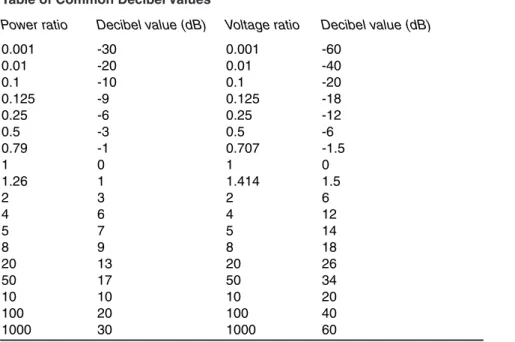
Table of Common Decibel Values
Power ratio Decibel value (dB) Voltage ratio Decibel value (dB)
0.001 -30 0.001 -60
0.01 -20 0.01 -40
0.1 -10 0.1 -20
0.125 -9 0.125 -18
0.25 -6 0.25 -12
0.5 -3 0.5 -6
0.79 -1 0.707 -1.5
1 0 1 0
1.26 1 1.414 1.5
2 3 2 6
4 6 4 12
5 7 5 14
8 9 8 18
20 13 20 26
50 17 50 34
10 10 10 20
100 20 100 40
1000 30 1000 60
Decibel values for ratios not in this table can often be calculated by using the property (a x b) in dB = (a) in dB + (b) in dB. Here are some examples:
• dB value of 25 = dB value of (5 x 5) = dB value of 5 + dB value of 5 = 7 + 7 = 14 dB • dB value of 40 = dB value of (20 x 2) = dB value of 20 + dB value of 2 = 13 + 3 = 16 dB • dB value of 0.2 = dB value of (0.1 x 2) = dB value of 0.1 + dB value of 2 = -10 + 3 = -7 dB
• dB value of 0.005 = dB value of (0.01 x 0.5) = dB value of 0.01 + dB value of 0.5 = -20 + (-3) = -23 dB
Special Decibel Abbreviations
You will often see the abbreviation dB followed by a letter. That means the value was calculated using a specif-ic reference value. The letter indspecif-icates that the value is “decibels with respect to…” followed by the reference value. For example, you will frequently see power levels given in dBm. The lower case “m” stands for milliwatt (mW), with 0 dBm corresponding to the reference power of 1 mW. 10 dBm would be 10 times that or 10 mW. -6 dBm would be ¼ mW. In other words, dBm is another way of referring to power. It can make life a bit easier if you’re doing system calculations. There are a number of other common abbreviations that specify certain reference levels and several are listed in the table. Table of Decibel Reference Abbreviations
Abbreviation Reference value
dBm one milliwatt (1 mW)
dBW one watt (1 W)
dBV one volt (1 V)
dBμV one microvolt (1 μV)
dBi gain of an isotropic antenna
dBd maximum gain of a half-wave dipole in free space
dBFS full-scale value
dBc carrier power
from en.wikipedia.org/wiki/Decibel
An example helps explain how dBm used. Say we have a transmitter that puts out 100 W, a feed line that has 3 dB loss and an antenna gain of 6 dB. Instead of having to use the decibel formula three times, convert the power to dBm
+50 dBm. Then we lose 3 dB in the coax, so we are down to +47 dBm (+50 minus the 3 dB loss). Finally, we gain 6 dB at the antenna for a net result of +53 dBm. We know this is 3 dB above 50 dBm, so the power is doubled to 200 W.
It is important to stress that while decibels represent change, dBm represents a particular power level. It’s like say-ing, “I have so many watts of power.” All the same rules of decibels apply when using dBm. How many dBm is 5 W of power? First, 1 W is 1000 mW or +30 dBm and 10 times that is 10 W, or +40 dBm. Half of that is +40 dBm – 3 dB or +37 dBm. Thus 5 W equals +37 dBm. You can find online calculators that convert between dBm and watts, such as the one at www.radius.net/power-to-dbm-conversion.html.
Decibels and Power Examples
Let’s suppose you have an amateur transmitter that operates on the 2 meter band. Your transmitter has an output power of 10 watts, but you would like a little more power to use to make contact with a distant station. An amplifier is just what you need. After connecting your new amplifier, you measure the output power again, and find it is now 100 watts. How many dB increase is this? We’ll use the 10-W signal as the reference in this case. Divide 100 W by 10 W to find the power ratio.
(Equation 1)
where
P0 is the reference power level
P1 is the power level compared to the reference power
1 0
P 100 W Power Ratio 10
P 10 W
= = =
Now find the logarithm of the power ratio. log (10) = log (101) = 1
Finally, multiply this result by 10 decibels = 10 × 1 = 10 dB
Your amplifier has increased the power of your 2 meter signal by 10 dB!
Now suppose the amplifier increased your signal to 1000 watts. Choose the reference power to be 10 W again, and divide the new power by the reference.
1 0
P Power Ratio
P =
1 0
P 1000 W Power Ratio 100
P 10 W
= = =
Find the logarithm of the power ratio. log (100) = log (102) = 2
Multiply this result by 10 to find the number of decibels. decibels = 10 × 2 = 20 dB
If we put all these steps together into a single equation, we once again have the definition of a decibel.
1 0
P decibels (dB) 10 log
P
=
(Equation 2) where
P0 is the reference power level
P1 is the power level compared to the reference power
Use this equation to calculate the number of decibels between power levels.
You should be aware of certain power ratios, because they occur so often. For example, let’s see what happens if we double a given power. Suppose we start with a circuit that has a power of 2 mW. What dB increase occurs if we double the power to 4 mW? We’ll start with the basic definition of a decibel.
1 0
P Power Ratio
P =
1 0
P dB 10 log
P
=
4 mW dB 10 log
2 mW
10 log (2) 10 0.3 3.0 dB
=
= = × =
When we double the power, there is a 3 dB increase. This is true no matter what the actual power levels are. Let’s look at an example with higher power levels to show that the dB increase is the same.
We measure the transmitter output power at an Amateur Radio station like the one shown in Figure 1, and find that it is 10 W. Use this power as a reference power for the station. After making some adjustments to the circuit, we measure the transmitter output power again. This time we find that the output power has increased to 20 W. What is the power increase, in dB? Equation 2 will help us answer this question.
1 0
P dB 10 log
P
=
20 W dB 10 log
10 W
10 log (2) 10 0.3 3.0 dB
=
= = × =
So our transmitter adjustments gave us a 3 dB increase in transmitter power.
Suppose you measured the power output from another transmitter, and found it to be 100 W. Later, after experimenting with a new circuit in the transmitter, you measure the output power as 50 W. What effect did your experiment have on the output power? What is the power change in decibels? Again, Equation 2 will help answer this question.
1 0
P dB 10 log
P
=
50 W dB 10 log
100 W 10 log (0.50)
10 ( 0.30) 3.0 dB
=
=
= × − = −
Although the power levels in our two examples were much different, we still had a 3 dB change. This is an Figure 1 — The output
power from an Amateur Radio transmitter is 10 watts. After making some adjustments to the transmitter tuning, you measure the power again. Now you find the power has increased to 20 watts. The text describes how to calculate the decibel increase that occurred.
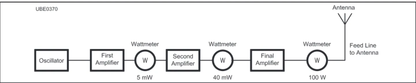
Figure 2 — A simple amateur transmitter amplifies the signal from an oscillator and then feeds that signal to an antenna. It uses several amplifier stages. The input power to one of those stages is 5 milliwatts and the output from that stage is 40 milliwatts. The text describes how to calculate the gain of that amplifier stage.
levels, not on the actual power. The 3 dB value is also important, because it shows that one power level was twice the other one. Increasing a power by two gives a 3 dB increase and cutting a power in half gives a 3 dB decrease.
Whenever you multiply or divide the reference power by a factor of 2, you will have a 3 dB change in power. You might guess, then, that if you multiplied the power by 4 it would be a 6 dB increase. If you multiplied the power by 8 it would be a 9 dB increase. You would be right in both cases!
Suppose the power in part of a circuit such as the one shown in Figure 2 measures 5 milliwatts and in another part of the circuit it measures 40 mW. Using the 5-mW value as the reference power, how many decibels greater is the 40-mW power?
1 0
P dB 10 log
P
=
40 mW dB 10 log
5 mW
10 log (8.0) 10 0.9 9.0 dB
=
= = × =
What happens if the power decreases? We can continue with the problem above, and measure the actual power arriving at the antenna. In this station, a long length of coaxial cable connects the transmitter to the antenna. Because some power is lost in this cable, we measure only 150 watts at the antenna. This time we’ll use the 1500 W amplifier output as our reference. We want to compare the power at the antenna with the amplifier power. Again, Equation 1 helps us answer our question.
1 0
P dB 10 log
P
=
150 W dB 10 log
1500 W
=
dB = 10 log (0.10) = 10 log (10–1)
dB = 10 × (–1) = –10 decibels
The negative sign tells us that we have less power than our reference. Of course, we knew that because there was less power at the antenna than the amplifier was producing. What happened to that power? Some of the energy going through the coaxial cable changed to heat, and there may be other losses in the cable. All coaxial cables would have some loss. 10 dB of cable loss means that 90% of the power entering it is lost to heat, and that leaves only 10% at the cable output. If the loss were 20 dB, then 99% of the power entering it would be lost to heat, and that would leave only 1% at the cable output. Most cables do not have this much loss — the ratios are only used as examples for practicing calculations.