1. Description
The Bluetooth converter provides a quick and easy
wireless connection between serial interfaces of the
V.24 (RS-232), RS-422, and RS-485 2-wire standard.
The wireless connection can extend up to 150 m
and is based on the international license-free Bluetooth
standard.
This wireless standard meets high requirements for
interference-free data transmission, in particular
through the use of the FHSS method (Frequency
Hopping Spread Spectrum) with the 2.4 GHz ISM
band.
The Bluetooth converter can be used for a wide
range of different applications, for example:
– Replacement of simple, serial point-to-point cabling
for V.24 (RS-232), RS-422, and RS-485 2-wire
interfaces.
– Creation of master/slave multi-drop connections.
– Wireless operation and monitoring for processes.
– Wireless parameterization, and diagnostic and
programming connections.
– Replacement of slip ring joints or drag chains.
– Implementation of high-quality electrical isolation
between the stations.
The
PSI-WL-RS232-RS485/BT
serial Bluetooth
converter is designed for industrial use and features
the following performance characteristics:
– Mounting by snapping on to an EN DIN rail
– Supply of 24 V DC or AC
– Transmission speed of up to 187.5 kbps
– Can be set to V.24 (RS-232), RS-422 or RS-485
– Supports all popular 10/11-bit UART data formats
– 3964R-compatible
– External antenna connection for optimum antenna
positioning
– Bluetooth access protected by password, fixed
device pairing or device access list
– Scalable transmission power (-28 to 20 dBm) for
specific localization of the radio cell
– Integrated Bluetooth path diagnostics indicate the
signal quality of the radio connection.
The
PSI-WL-RS232-RS485/BT
Bluetooth converter
is accessed via a second, identical device or via the
PSI-WL-PLUG-RS232/BT
V.24 (RS-232) adapter,
which is in the form of a connector. Wireless access via
third-party devices, which already have an integrated
Bluetooth interface, e.g., PDA, notebook or cell phone,
is also supported (see page 2).
Should you have any technical questions, please
contact us:
PSM HOTLINE: +49 - 52 35 - 31 98 90
FAX: +49 - 52 35 - 31 98 99
E-mail: interface-service@phoenixcontact.com
Serial Bluetooth Converter for V.24 (RS-232), RS-422, and
RS-485 2-Wire Bus Systems
PSI-WL-RS232-RS485/BT
Headquarters: © Phoenix Contact GmbH & Co. KG • Flachsmarktstraße 8 • 32825 Blomberg • Germany
Phone +49 - 52 35 - 30 0 • Fax +49 - 52 35 - 34 12 00 • www.phoenixcontact.com
Local contact: www.phoenixcontact.com/salesnetwork
PHOENIX CONTACT page 2 of 8
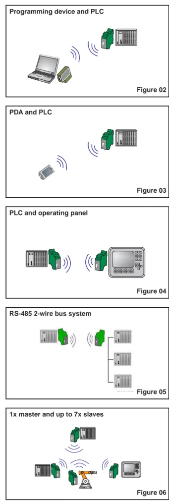
Figure 03
PDA and PLC
2.1 Point-to-Point Connections
Point-to-Point
Without Termination Device Addressing
(V.24 (RS-232), RS-422, etc.)
– Direct programming connection between a laptop
and a programmable logic controller (Figure 02).
– Data connection between a third-party device with
integrated Bluetooth interface (PDA, cell phone,
etc.) and an industrial controller (Figure 03).
– Connection between a mobile operator interface
and an industrial controller (Figure 04).
Point-to-Point
With Termination Device Addressing
(RS-485 2-Wire)
– Integration of a device into an existing bus system,
e.g., Modbus, PROFIBUS, etc. (Figure 05).
2.2 Multi-Drop Connections
Networking for automation components.
Up to seven Bluetooth slaves can be connected
to a Bluetooth master (Figure 06).
Figure 02
Programming device and PLC
Figure 04
PLC and operating panel
Figure 05
RS-485 2-wire bus system
Figure 06
1x master and up to 7x slaves
Serial Bluetooth Converter for V.24 (RS-232), RS-422, and RS-485 2-Wire Bus – PSI-WL-RS232-RS485/BT
Serial Bluetooth Converter for V.24 (RS-232), RS-422, and RS-485 2-Wire Bus – PSI-WL-RS232-RS485/BT
3. Technical Data
Description
Bluetooth converter for converting V.24 (RS-232)/RS-422/
RS-485 2-wire to Bluetooth, range up to 150 m, DIN rail mounting, 24 V supply.
Scope of supply:
DIN-rail mountable Bluetooth device, CD with configuration software and user manual
Accessories
Lambda/4 antenna with omni-directional characteristics,
mounting bracket, antenna cable with angled antenna connector. Gain
Polarization Impedance Degree of protection Dimensions
1.50 m MCX 2 dBi Omni, vertical
50 Ω
IP65
∅ 8.2 mm x 82.5 mm
Panel antenna with directional characteristics,
mounting clamp and antenna connection. Gain
Polarization Impedance Degree of protection Dimensions (H x W x D)
∅ 40 mm to 60 mm
SMA 8 dBi Linear, vertical
50 Ω
IP55 101 mm x 80 mm x 20 mm
Coaxial antenna cable for panel antenna.
Connections Attenuation Impedance
1 m (3.28 ft.)
MCX/SMA 2 dB
50 Ω
PSI-WL-RS232-RS485/BT
UL (in preparation)Type Order No. Pcs.Pkt.
PSI-WL-RS232-RS485/BT 27 08 51 7 1
RAD-ISM-2400-ANT-OMNI-2-1 28 67 46 1 1
RAD-ISM-2400-ANT-PAN-8-0 28 67 61 0 1
RAD-PIG-EF316-MCX-SMA 28 67 67 8 1
99
1 1 4 , 5 2 2 , 5
( 4 . 5 0 8 " ) ( 0 . 8 8 6 " )
(3
.8
98
")
6 1 4 5 1 0 0 1
P S I W L R S 2 3 2 -R S 4 8 5 / B T O r d . - N o . 2 7 0 8 5 1 7
V C C T D R D B T S I G N A L S E R E R R
R E S A N T
R
S 2
32
r e d S E R E R R
M C X A N T
µ C
B l u e -
t o o t h
P u s h b u t t o n R E S
B
T
S
ig
na
l g n
g n y e g n y e T D R D 7 D -S U B -9 R S-23 2
T x D 3
R x D 2
R T S
8
C T S
6
D S R
4
D T R
5
G N D
D C E
S W - S w i t c h H W - S w i t c h
C O N F
R U N R S 2 3 2
R S 4 2 2 R S 4 8 5 D ( A )
G N D D ( B ) T ( A ) T ( B )
( S h i e l d )
C O M B IC O N R S-42 2 / R S4 85 W 2
2 4 V 0 V 2 4 V 0 V B ac kp la ne VC
C V C C g n
+ 5 V 2 4 V
5 V
T e r m i n a t i o n + 5 V 3 9 0W 1 5 0W 3 9 0W
PHOENIX CONTACT page 4 of 8
Serial Bluetooth Converter for V.24 (RS-232), RS-422, and RS-485 2-Wire Bus – PSI-WL-RS232-RS485/BT
Additional Accessories System power supply primary switched.
Input voltage range Nominal output voltage Nominal output current
45 to 65 Hz 85 to 264 V AC 24 V DC ±1% 1.5 A
DIN rail bus connector Technical Data Supply
Supply voltage 1 (function elements 12 - 13)
Supply voltage 2 (alternative or redundant)
Frequency
Nominal current consumption
LED indicator (function element 9)
Configuration
System requirements Configuration interface
V.24 (RS-232) Interface
Physics
Connection (function element 1)
Device type
Signal assignment Data format Encoding
Protocols
Serial transmission speed
Data flow control
Default upon delivery
LED indicator/serial data indicator (function elements 7 - 8)
LED indicator/serial system diagnostics (function element 2)
Type Order No. Pcs.Pkt.
MINI-SYSPS-100-240AC/24DC/1.5 28 66 983 1
ME 22,5 TBUS 1,5/ 5-ST-3,81 GN 27 07 437 1
10 to 30 V DC, 24 V AC ±20%
Via plug-in COMBICON screw terminal block Protection against polarity reversal via bridge rectifier 24 V DC ±20%
Via backplane bus contact and appropriate system power supply, protection against polarity reversal via series diode.
DC or 50 to 60 Hz 40 mA at 24 V DC 70 mA RMS at 24 V AC VCC (green LED):
- Steady light during operation in RUN mode - Flashing during operation in CONF mode
Windows 98 SE, 2000, NT4, XP V.24 (RS-232), Bluetooth,
The system is configured in CONF mode via the V.24 (RS-232) interface and the configuration software provided.
Either the local device is configured or a remote device is configured via Bluetooth.
EIA/TIA RS-232 9-pos. D-SUB pin strip
DCE (Data Communication Equipment) with 1:1 cable to DTE (Data Terminal Equipment).
TxD = 3, RxD = 2, RTS = 7, CTS = 8, DTR = 4, DSR = 6, GND = 5 Serial asynchronous UART/NRZ
7/8 data, 1/2 stop, 1 parity, 10/11-bit character length can be adjusted via software.
Transparent protocol, including 3964R protocol
0.3, 1.2, 2.4, 4.8, 7.2, 9.6, 19.2, 31.25, 38.4, 57.6, 75, 93.75, 115.2, 136, 187.5 kbps can be adjusted via software.
Hardware handshake:
- Termination device directly with the Bluetooth converter via RTS/CTS
- Data transmission speed of up to 187.5 kbps
Software handshake (Xon/Xoff):
- Software handshake is negotiated directly between the termination devices
- Setting on Bluetooth converter = "none" - Data transmission speed of up to 38.4 kbps
Message-oriented protocols, e.g., Modbus, PROFIBUS, etc.:
- Setting on Bluetooth converter = "none" - Data transmission speed of up to 93.75 kbps 9.6 kbps, 8 data, no parity,
1 stop bit, hardware handshake
TD (yellow LED), dynamic, serial port is transmitting data, RD (green LED), dynamic, serial port is receiving data SER ERR (red LED),
Serial Bluetooth Converter for V.24 (RS-232), RS-422, and RS-485 2-Wire Bus – PSI-WL-RS232-RS485/BT
RS-422/RS-485 2-Wire
Physics
Connection (function elements 10 - 11, 14 - 17)
Termination resistor/termination (function element 19)
Signal assignment for RS-422
Signal assignment for RS-485 2-wire
Bluetooth Interface
Physics Frequency Channel distance Bandwidth Channels
Transmission method
Radio approvals USA (in preparation):
Canada (in preparation): Europe:
Approved countries:
Notification R&TTE device class Usage restrictions according to ERC Recommendation 70-03/April 2004
Bluetooth device class Transmission power
Range guide values
(depending on the application environment)
Receiver sensitivity Antenna
Antenna connection (function element 18) Bluetooth profile
Number of Bluetooth masters/Bluetooth slaves
LED indicator/Bluetooth data indicator (function element 3)
LED indicator/Bluetooth transmission quality (function elements 3 - 5)
(function elements 3 - 4) (function element 3)
EIA/TIA RS-422 and RS-485 2-wire, can be switched via configuration software, default upon delivery is V.24 (RS-232) Plug-in COMBICON screw terminal block
390 - 150 - 390 Ω can be enabled in the device, default upon
delivery is OFF
Transmit pos. = TB, Transmit neg. = TA, Receive pos. = DB, Receive neg. = DA Signal ground = GND, Shield connection = FE Transmit/Receive pos. = DB, Transmit/Receive neg. = DA Bluetooth 1.1 Specification
2.402 GHz to 2.480 GHz (ISM band 2.4 GHz) 1 MHz
79 MHz 79
Frequency hopping 1.6 kHz (FHSS) FCC/CFR 47, Part 15
RSS-210
ETSI EN 300 328, 300 826
EU countries:
Belgium, Denmark, Germany, Estonia, Finland, France, Greece, Great Britain, Ireland, Italy, Latvia, Lithuania, Luxembourg, Malta, Netherlands, Austria, Poland, Portugal, Sweden, Slovakia, Slovenia, Spain, Czech Republic, Hungary, Cyprus
Non-EU countries:
Iceland, Norway, Switzerland, USA, Canada Other countries on request
EU countries, Iceland, Switzerland, Norway Class 2
France: Outside buildings the
maximum transmission power is 10 mW (10 dBm), (note antenna data and software settings)
Italy: Outside buildings a license is required for operation and
the maximum transmission power is 10 mW (10 dBm), (note antenna data and software settings)
Class 1 = 100 mW (20 dBm), maximum 20 dBm = default upon delivery,
can be set via software from -28 dBm to +20 dBm 20 dBm = 80 m to 150 m
10 dBm = 40 m to 70 m 0 dBm = 10 m to 30 m -80 dBm at 0 dBi antenna gain
External antenna, not included in the scope of supply, (see list of accessories)
MCX
- GAP (Generic Access Profile)
(method for authentication and connection establishment) - SDAP (Service Discovery Application)
(method for requesting supported services) - SPP (Serial Port Profile)
(COM port emulation method) - DUN (Dial-up Networking Profile) (modem dial-up method) - LAP (LAN Access Point Profile) (network connection method) 1x master/7x slaves
BT SIGNAL (1x yellow LED flashing), Bluetooth is transmitting/receiving data
BT SIGNAL (1x yellow LED, 2x green LEDs), very good reception BT SIGNAL (1x yellow LED, 1x green LED), good reception BT SIGNAL (1x yellow LED), poor reception, close to the system reserve
PHOENIX CONTACT page 6 of 8
Serial Bluetooth Converter for V.24 (RS-232), RS-422, and RS-485 2-Wire Bus – PSI-WL-RS232-RS485/BT
General Data
CE conformance Approvals
Ambient operating temperature range during operation Housing
- Material
- Dimensions (H x W x D in mm) Weight of device
Functional earth ground Vibration resistance
Shock test
Free fall
Degree of protection Air and creepage distances Ambient compatibility
Separate ground levels Test voltage
According to R&TTE Directive 1999/5/EC UL (in preparation)
-20°C to +60°C.
ME 22,5 LWL LINE with 5-pos. ME-T bus contact and ground contact ABS-VO, green
99 x 22.5 x 114.5 mm 120 g, approximately Housing contact with DIN rail According to DIN EN 60068-2-6 5g, 2.5 h in each x, y, and z direction Criterion A (no functional disruption) According to DIN EN 60068-2-27 15 g, 11 ms pulse length
Criterion C (module is not damaged)
According to DIN EN 60950 from a height of 1 m. without packaging IP20
According to VDE 0110-1, DIN EN 50178, DIN EN 60950
Free from substances, which would hinder coating with paint or varnish according to central standard P-VW 3.10.7 -3.10 0.757 650 of VW, Audi, and Seat (chloroform test)
24 V supply // 5 V logic + serial ports // functional earth ground 1.5 kV AC, 50 Hz, 1 min. between all ground levels
c
c
c
c
According to R&TTE Directive 1999/5/EC:
EMC*)
Noise immunity (Electromagnetic Compatibility)
Safety
Protection of personnel with regard to electrical safety.
Health
Limitation of exposure of the population to electromagnetic fields.
Radio
Effective use of the frequency spectrum and prevention of radio interference.
*) Addition: EMC (Electromagnetic Compatibility)
Noise Immunity According to EN 61000-6-2 • Electrostatic discharge (ESD)
• Electromagnetic HF field Amplitude modulation Pulse modulation • Fast transients (burst) Signal:
Supply:
• Surge current loads (surge) Signal:
Supply:
• Immunity to conducted interference
• Noise emission: Conducted emission Radiated emission
EN 61000 corresponds to IEC 1000 EN 55011 corresponds to CISPR11
1) Criterion A: Normal operating characteristics within the specified
limits.
2) Criterion B: Temporary adverse effects on the operating
characteristics that the device corrects automatically.
Class A: Industrial application, without special
installation measures.
EN 61000-6-2:2001
EN 60950 : 2001
EC Gazette 1999/519/EC
ETSI EN 300 328: V1.2.1, V1.4.1
Generic standard for the industrial sector
EC Council recommendation of July 12, 1999
EN 61000-4-2 EN 61000-4-3
EN 61000-4-4
EN 61000-4-5
EN 61000-4-6
EN 55011 ETSI EN 300 328
8 kV air discharge 2)
6 kV contact discharge 2)
10 V/m 1)
10 V/m 1)
2 kV/2 min. 2)
2 kV/2 min. 2)
1 kV/42 Ω2)
0.5 kV/2 Ωsymmetrical2)
0.5 kV/12 Ωasymmetrical2)
10 V/m 1)
Class A
PHOENIX CONTACT page 8 of 8
1.
9-pos. D-SUB
, V.24 (RS-232) data interface
2.
Red LED
, incorrect interface setting or
buffer overrun
3.
Yellow LED
, poor reception, close to the
system reserve
4.
Green LED
, good reception
5.
Green LED
, very good reception
6.
Pushbutton
, to reset settings
7.
Green LED
, dynamic, serial port is receiving
data
8.
Yellow LED
, dynamic, serial port is transmitting
data
9.
Green LED
, steady light during operation in
RUN mode, flashing during operation in
CONF mode
10.
6666
, shield connection
6 1 4 5 1 0 0 1
P S I W L R S 2 3 2 -R S 4 8 5 / B T O r d . - N o . 2 7 0 8 5 1 7
V C C T D R D
B T S I G N A L S E R E R R
R E S A N T
R
S
2
32
1 3
1 2
1 4 1 5
1 6
1 7
1 8
5
4
3
2
8
7
6
9
1
1 0
1 1
A
B
Figure 09
19
20
Serial Bluetooth Converter for V.24 (RS-232), RS-422, and RS-485 2-Wire Bus – PSI-WL-RS232-RS485/BT
4. Function Elements/Diagnostics
11.
GND
, operating ground
12.
VCC
, supply of 10 to 30 V DC, 24 V AC ±20%
13.
0 V
, supply of 0 V
14.
TA
, RS-422: Transmit negative
15.
TB
, RS-422: Transmit positive
16.
DA
, RS-422: Receive negative
RS-485 2-wire: Transmit/Receive negative
17.
DB
, RS-422: Receive positive
RS-485 2-wire: Transmit/Receive positive
18.
MCX connection
, for external antenna
19.
Switch for
RS-422/RS-485 Terminate ON/OFF
20.
Switch for
CONF/RUN
PHOENIX CONTACT
11/15/04
TNR:102403-00-GB