GEOTECHNICAL
ENGINEERING
REPORT
Jenks Avenue Commercial Development
Additional Borings
Panama City, Bay County, Florida
PREPARED FOR:
Mr. Bradley Bromlow
NOVA Project Number: 10111-2019176 November 5, 2019
November 5, 2019 Mr. Bradley Bromlow
Subject: Geotechnical Engineering Report
Jenks Avenue Commercial Development Additional Borings Panama City, Bay County, Florida
NOVA Project Number 10111-2019176 Dear Mr. Bromlow,
NOVA Engineering and Environmental LLC (NOVA) has completed the authorized subsurface exploration and geotechnical engineering evaluation for the proposed commercial development to be constructed in Panama City, Bay County, Florida. The work was performed in general accordance with NOVA proposal number 011-20192886, dated October 23, 2019. This report briefly discusses our understanding of the project at the time of the subsurface exploration, describes the geotechnical consulting services provided by NOVA, and presents our findings, conclusions and recommendations.
We appreciate your selection of NOVA and the opportunity to be of service on this project. If you have any questions, or if we may be of further assistance, please do not hesitate to contact us. Sincerely,
NOVAENGINEERING AND ENVIRONMENTAL LLC
Jacob Prout, E.I. Andre Kniazeff, P.E.
Staff Engineer Senior Geotechnical Engineer
Florida Registration No. 1100022178 Florida Registration No. 81315
TABLE OF CONTENTS
1.0 SUMMARY ... 2
1.1 GENERAL ... 2
1.2 SITEPREPARATION ... 2
1.3 GROUNDWATERCONTROL... 2
1.4 FOUNDATIONRECOMMENDATIONS ... 3
1.5 PAVEMENTRECOMMENDATIONS ... 3
2.0 INTRODUCTION ... 4
2.1 PROJECTINFORMATION ... 4
2.2 SCOPEOFWORK ... 4
3.0 SITE DESCRIPTION ... 6
3.1 LOCATIONANDLEGALDESCRIPTION ... 6
3.2 SUBJECTPROPERTYVICINITYGENERALCHARACTERISTICS ... 6
3.3 CURRENTUSEOFTHEPROPERTY ... 6
4.0 FIELD AND LABORATORY PROCEDURES ... 7
4.1 FIELDEXPLORATION ... 7
4.2 LABORATORYTESTING ... 8
5.0 SUBSURFACE CONDITIONS ... 10
5.1 GEOLOGY ... 10
5.2 SOILCONDITIONS ... 10
5.3 GROUNDWATERCONDITIONS ... 10
6.0 CONCLUSIONS AND RECOMMENDATIONS ... 12
6.1 SITEPREPARATION ... 12
6.2 FILLPLACEMENT ... 12
6.3 GROUNDWATERCONTROL... 14
6.4 FOUNDATIONRECOMMENDATIONS ... 14
6.5 SLAB-ON-GRADE ... 16
6.6 PAVEMENT RECOMMENDATIONS ... 16
7.0 CONSTRUCTION OBSERVATIONS ... 20
7.1 SHALLOWFOUNDATIONS ... 20
7.3 SUBGRADE ... 20
APPENDICES
APPENDIX A – FIGURES & MAPS APPENDIX B – SUBSURFACE DATA APPENDIX C – LABORATORY DATA APPENDIX D – SUPPORT DOCUMENTS
1.0
SUMMARY
A brief summary of pertinent findings, conclusions and recommendations is presented below. This information should not be utilized in design or construction without reading all of the recommendations presented in the text and Appendix of this report.
1.1 GENERAL
Our field exploration at the subject site consisted of performing one (1) Standard Penetration Test (SPT) boring within the extended footprint of the proposed structure and three (3) auger borings within the proposed pavement areas. Drilling, testing and sampling operations were performed in general accordance with ASTM designations and other industry standards.
The test borings generally encountered mixed strata of loose to medium dense fine-grained sands to silty fine-fine-grained sands (USCS classifications of SP, SP-SM, SP-SC and SM) with varying amounts of organics from the existing ground surface elevation to the maximum depth explored of about 25 feet below existing grade (BEG).
1.2 SITE PREPARATION
We recommend removing all topsoil and surficial vegetation, trees and associated root systems, and any other deleterious non-soil materials that are found to be present from within the proposed construction limits. Exposed subgrade soils at the undercut elevations, as well as subsequent lifts of fill soils, should be compacted to a minimum soil density of at least 95 percent of the maximum dry density as determined by the Modified Proctor test (ASTM D-1557). The top 12 inches of pavements subgrades, as well as all footing excavations, should be compacted to at least 98 percent. We note that vibratory compaction operations should not be performed within a clear distance of 50 feet from any adjacent structures.
A geotechnical engineer should carefully evaluate all subgrades prior to foundation and slab-on-grade construction to confirm compliance with this report; evaluate geotechnical sections of the plans and specifications for the overall project; and provide additional recommendations that may be required.
1.3 GROUNDWATER CONTROL
Groundwater was encountered in the test borings at depths ranging between about 1½ feet to 4¼ feet BEG at the time of our subsurface exploration, which occurred
during a period of relatively normal seasonal rainfall. Groundwater should therefore be
expected to impact the planned near surface construction, most especially during shallow foundation and subsurface utility installations in lower-lying areas of the site.
Contractors should be prepared to utilize a significant dewatering system during construction to maintain adequate separation between the groundwater levels and the desired working platforms for below-grade work.
1.4 FOUNDATION RECOMMENDATIONS
After the recommended site/subgrade preparation and fill placement, we recommend that the proposed structure be supported on a conventional shallow foundation system bearing upon compacted native soils and/or compacted structural fill. The building foundation may be designed for a maximum soil bearing pressure of 2,000 pounds per square foot (psf). We note that sufficient fill should be added to the site to provide a minimum separation of at least 2 feet between the seasonal high groundwater (SHGW) table, which is estimated to occur approximately 1 foot to 1½ feet above the groundwater levels measured at each boring location during our field explorations, and the lowest bottom-of-footing elevation planned for the proposed structure.
1.5 PAVEMENT RECOMMENDATIONS
We understand that the infrastructure for the planned development will include flexible (asphalt) or rigid pavements for the entrance drives and parking areas. Based on the results of our test borings, the subsurface conditions encountered appear to be adaptable for supporting these pavement sections, provided that a minimum separation of at least 24 inches between the bottom of a crushed limerock base course and the seasonal high groundwater table can be maintained. This separation may be reduced to 18 inches if Graded Aggregate Base (GAB) is employed for this project in lieu of crushed limerock base.
2.0
INTRODUCTION
2.1 PROJECT INFORMATION
Our understanding of the proposed development is based on recent conversations and email exchanges with the Client, review of the provided site plan and aerial photography of the site via internet-based GIS software; our site reconnaissance activities; and our experience with similar geotechnical conditions in the near vicinity to this project site.
2.1.1 SITE PLANS AND DOCUMENTS
Final Architectural or Structural plans were not provided to us. We were furnished with the following document:
• Document: Site Plan with requested boring locations
Provided by: Client Dated: Not Dated
2.1.2 PROPOSED CONSTRUCTION
NOVA understands that the project will consist of the construction of a single-story pre-engineered metal building (PEMB) with a plan footprint on the order of
10,000 ft2, associated paved drives and parking areas, and a stormwater
management system (SMS) to treat and dispose of stormwater runoff associated with the planned site improvements. We understand that the structure will be supported on a conventional shallow foundation system consisting of a monolithic slab. Structural details were not available from the design team at the time of the issuance of this report; we have therefore assumed that maximum loadings for the proposed structure will not exceed 30 kips per column for isolated interior columns and 3 kips per lineal foot for continuous load bearing walls.
2.1.3 SITE GRADING
Site grading details were not provided at the time of issuance of this report, we therefore assume finished site grades will not change greater than +/- 3 feet from existing grades within the proposed structure footprint and paving areas.
2.2 SCOPE OF WORK
Mr. Bradley Bromlow engaged NOVA to provide additional geotechnical engineering consulting services for the proposed project. This report briefly discusses our understanding of the project, describes our exploratory procedures, and presents our findings, conclusions, and recommendations.
The primary objective of this study was to perform a geotechnical exploration within the proposed construction areas and to assess these findings as they relate to geotechnical aspects of the planned site improvements. The authorized geotechnical engineering services included a soil test boring and sampling program, laboratory testing, engineering evaluation of the field and laboratory data, and the preparation of this report. The services were performed substantially as outlined in our proposal number 011-20192886, dated October 23, 2019, and in general accordance with industry standards.
As authorized per the above referenced proposal, this completed geotechnical report includes:
• A description of the site, fieldwork, laboratory testing and general soil conditions
encountered, a Boring Location Plan, and individual Test Boring Records.
• Site preparation considerations that include geotechnical discussions regarding
site stripping and subgrade preparation, and engineered fill/backfill placement.
• Recommendations for controlling groundwater and/or run-off during construction,
and the need for permanent dewatering systems based on the anticipated post construction groundwater levels.
• Foundation system recommendations for the proposed structure, as appropriate
based on the boring results.
• Slab-on-grade construction considerations based on the geotechnical findings,
including the need for a sub-slab vapor barrier or a capillary barrier.
• Estimated seasonal high groundwater levels within the pavement areas.
• Recommended pavement sections based on assumed traffic loading and
estimated subgrade strengths determined by soil types collected from the auger borings.
• Suitability of on-site soils for re-use as structural fill, backfill, and subgrade.
Additionally, the criteria for suitable fill materials will be provided.
• Recommended quality control measures (i.e. sampling, testing, and inspection
requirements) for site grading, pavement and foundation construction.
The assessment of site environmental conditions, including the presence of wetlands or detection of pollutants in the soil, rock or groundwater, laboratory testing of samples, or a site-specific seismic study was beyond the scope of this geotechnical study. If requested, NOVA can provide these services.
3.0
SITE DESCRIPTION
3.1 LOCATION AND LEGAL DESCRIPTION
The Subject Property (Bay County Parcel I.D. Number 13003-100-010) consists of a 1.22-acre lot that is located at the southeast corner of the intersection of Jenks Avenue and Jazz Drive in Panama City, Bay County, Florida. A site location map is provided in Appendix A.
3.2 SUBJECT PROPERTY VICINITY GENERAL CHARACTERISTICS
At the time of our field exploration, the vicinity of the Subject Property generally consisted of light commercial, residential and undeveloped properties.
3.3 CURRENT USE OF THE PROPERTY
At the time of our field exploration, the Subject Property was observed to be vacant undeveloped land.
4.0
FIELD AND LABORATORY PROCEDURES
4.1 FIELD EXPLORATION
The boring locations were established in the field by NOVA personnel using a handheld GPS unit. Consequently, referenced boring locations should be considered approximate. If the client desires increased accuracy, NOVA recommends that the boring locations and elevations be surveyed.
Our field exploration included performing:
• One (1) SPT boring advanced to a depth of approximately 25 feet BEG within the
extended footprint of the proposed structure.
• Three (3) auger borings advanced to depths of 3 feet to 5 feet BEG within the
proposed pavement areas.
SPT Boring: The Standard Penetration Test boring was performed using the guidelines of ASTM Designation D-1586, "Penetration Test and Split-Barrel Sampling of Soils". A mud rotary drilling process was used to advance the borings. At regular intervals, soil samples were obtained with a standard 1.4-inch I.D., 2.0-inch O.D., split-tube sampler. The sampler was first seated six inches and then driven an additional foot with blows of a 140-pound hammer falling 30 inches. The number of hammer blows required to drive the sampler the final foot is designated the "Penetration Resistance". The penetration resistance, when properly interpreted, is an index to the soil strength and density. Representative portions of the soil samples, obtained from the sampler, were placed in sealed containers and transported to our laboratory for further evaluation and laboratory testing.
Auger Borings: The auger borings were performed using hand operated soil samplers. At regular intervals, soil samples were obtained from a standard 3-inch O.D. sampler. Representative portions of the soil samples, obtained from the sampler, were placed in sealed containers and transported to our laboratory for further evaluation and laboratory testing.
Test Boring Records in Appendix B present the soil conditions encountered in the borings. These records represent our interpretation of the subsurface conditions based on the field exploration data, visual examination of the recovered samples, laboratory test data, and generally accepted geotechnical engineering practices. The stratification lines and depth designations represent approximate boundaries between various subsurface strata. Actual transitions between materials may be gradual.
Groundwater Levels: The groundwater levels reported on the Test Boring Records represent measurements made at the completion of each test boring. The test borings
were subsequently backfilled with soil cuttings from the drilling process for safety concerns.
4.2 LABORATORY TESTING
A laboratory testing program was conducted to characterize materials existing at the site using split spoon and bulk/grab soil samples recovered from the borings. The laboratory test data are presented in the Appendix. Selected test data are also presented on the Test Boring Records attached in the Appendix. The specific tests are briefly described below. Further laboratory testing was beyond the scope of this exploration. It should be noted that all soil samples will be properly disposed of 30 days following the submittal of this NOVA subsurface exploration report unless you request otherwise.
4.2.1 SOIL CLASSIFICATION
Soil classification provides a general guide to the engineering properties of various soil types and enable the engineer to apply past experience to current problems. In our explorations, samples obtained during drilling operations are observed in our laboratory and visually classified by an engineer. The soils are classified according to relative density (based on SPT N-values), color and texture. These classification descriptions are included on our Test Boring Records. The classification system discussed above is primarily qualitative; laboratory testing is generally required for detailed soil classification. Using the test results, the soils were visually/manually classified according to the Unified Soil Classification System. This classification system and the in-place physical soil properties provide an index for estimating the soil's behavior. The soil classification and physical properties obtained are presented in this report.
4.2.2 MOISTURE CONTENT
The moisture content is the ratio expressed as a percentage of the weight of water in a given mass of soil to the weight of the solid particles. This testing was conducted in general accordance with ASTM D-2216. Three (3) moisture content tests were performed in this study.
4.2.3 FINES CONTENT
The percentage of fines passing through the No. 200 sieve is generally considered to represent the amount of silt and clay of the tested soil sample. This testing was conducted in general accordance with ASTM Designations D-6913 and D-1140. Three (3) fines content tests were performed in this study.
4.2.4 ORGANIC CONTENT
The organic content is the ratio expressed as a percentage of the weight of organic material in a given mass of soil to the weight of the solid particles. This testing was conducted in general accordance with ASTM D-2974. One (1) organic content test was performed in this study.
5.0
SUBSURFACE CONDITIONS
5.1 GEOLOGY
The site is located in Bay County, Florida and according to the United States Geological Survey (USGS), is situated within the Gulf Coastal Plain, separated from the Florida Platform by geologic structures known as the Gulf Trough and Apalachicola Embayment. These structures formed a bathymetric and environmental barrier from the earliest Eocene or earliest Oligocene periods into the Miocene.
According to the “Text to Accompany the Geologic Map of Florida” by Scott, 2001, the site is generally underlain by sediments deposited during the Holocene period. These sediments typically consist of quartz sands, carbonate sands and muds, and organics. Surficial soils in the region are primarily siliciclastic sediments deposited in response to the renewed uplift and erosion in the Appalachian highlands to the north and sea-level fluctuations. The extent and type of deposit is influenced by numerous factors, including mineral composition of the parent rock and meteorological events.
5.2 SOIL CONDITIONS
The following paragraph provides a generalized description of the subsurface profile and soil conditions encountered by the borings. The Test Boring Records provided in the Appendix should be reviewed to provide more detailed descriptions of the subsurface conditions encountered at the boring locations. Conditions may vary at other locations and times.
The test borings generally encountered mixed strata of loose to medium dense fine-grained sands to silty fine-fine-grained sands (USCS classifications of SP, SP-SM, SP-SC and SM) with varying amounts of organics from the existing ground surface elevation to the maximum depth explored of about 25 feet below existing grade (BEG).
5.3 GROUNDWATER CONDITIONS
5.3.1 GENERAL
Groundwater in the Gulf Coastal Plain typically occurs as an unconfined aquifer condition. Recharge is provided by the infiltration of rainfall and surface water through the soil overburden. More permeable zones in the soil matrix can affect groundwater conditions. The groundwater table is expected to be a subdued replica of the original surface topography. Based on a review of topographic maps and our visual site observations, we anticipate the groundwater flow at the site to be generally towards the west.
5.3.2 SOIL TEST BORING GROUNDWATER CONDITIONS
Groundwater was encountered in the test borings at depths ranging between about 1½ feet to 4¼ feet BEG at the time of our subsurface exploration, which
occurred during a period of relatively normal seasonal rainfall.
Based on our review of the subsurface conditions encountered in the test borings, we estimate that the normal permanent seasonal high groundwater (SHGW) table for this property will occur approximately 1 foot to 1½ feet above the groundwater levels measured at each boring location during our field explorations.
Groundwater levels vary with changes in season and rainfall, construction activity, surface water runoff and other site-specific factors. Groundwater levels in the Bay County area are typically lowest in the late spring and the late fall and highest in the summer with annual groundwater fluctuations by seasonal rainfall; consequently, the water table may vary at times.
6.0
CONCLUSIONS AND RECOMMENDATIONS
The following conclusions and recommendations are based on our understanding of the proposed construction, our site observations, our evaluation and interpretation of the field and laboratory data obtained during this exploration, our previous experience with the project site, and generally accepted geotechnical engineering principles and practices.
Subsurface conditions in unexplored locations or at other times may vary from those encountered at specific boring locations. If such variations are noted during construction, or if project development plans are changed, we request the opportunity to review the changes and amend our recommendations, if necessary.
As previously noted, the boring locations were established in the field using a handheld GPS unit. If increased accuracy is desired by the client, we recommend that the boring locations and elevations be surveyed.
6.1 SITE PREPARATION
We recommend removing all topsoil and surficial vegetation, trees and associated root systems, and any other deleterious non-soil materials that are found to be present from within the proposed construction limits. Exposed subgrade soils at the undercut elevations, as well as subsequent lifts of fill soils, should be compacted to a minimum soil density of at least 95 percent of the maximum dry density as determined by the Modified Proctor test (ASTM D-1557). We note that vibratory compaction operations should not be performed within a clear distance of 50 feet from any adjacent structures.
A geotechnical engineer should carefully evaluate all subgrades prior to foundation, slab-on-grade, and pavement section construction to confirm compliance with this report; evaluate geotechnical sections of the plans and specifications for the overall project; and provide additional recommendations that may be required.
6.2 FILL PLACEMENT
6.2.1 FILL SUITABILITY
We anticipate that up to 3 feet of fill will be required to achieve the desired finished subgrade elevations within the proposed structure footprint and pavement areas, and where possible materials over-excavated from the planned SMS basin are desired to be utilized as fill/backfill materials.
Fill materials should be relatively clean sands with less than 12 percent fines (material passing the No. 200 sieve), and free of non-soil materials and rock fragments larger than 3 inches in diameter. On-site near surface soils that are
categorized as slightly silty fine-grained sands (SP-SM) based on the Unified Soil Classification System (USCS) are considered suitable for the use of structural fill in the building and pavement areas, provided that the materials are free of rubble, clay, rock, roots and organics. Soils with fines contents between 13 and 25 percent (SM) may also be used as fill soils for this project, but we note that strict moisture control would be required at the time of placement for these moisture-sensitive soils.
All materials to be used for backfill or compacted fill construction should be evaluated and, if necessary, tested by NOVA prior to placement to determine if they are suitable for their intended use. Any off-site materials used as fill should be approved by NOVA prior to acquisition. Organic and/or debris-laden material is not suitable for re-use as structural fill.
6.2.2 SOIL COMPACTION
Fill should be placed in thin, horizontal loose lifts (maximum 12-inch depth) and compacted to a minimum soil density of at least 95 percent of the Modified Proctor maximum dry density (ASTM D-1557). The upper 12 inches of soil
beneath the bottoms of all shallow foundation footings,as well as the top 12
inches of subgrade soils in the pavement areas, should be compacted to at least 98 percent. In confined areas, such as utility trenches, portable compaction equipment and thinner fill lifts (3 to 4 inches) may be necessary. Fill materials used in structural areas should have a target maximum dry density of at least 100 pounds per cubic foot (pcf). If lighter weight fill materials are used, the NOVA geotechnical engineer should be consulted to assess the impact on design recommendations.
Soil moisture content should be maintained within 3 percent of the optimum moisture content. We recommend that the grading contractor have equipment on site during earthwork for both drying and wetting fill soils. Moisture control
may be difficult during rainy weather. Soils excavated from below the
groundwater table will likely require significant efforts to achieve acceptable moisture contents prior to re-use as fill.
Filling operations should be observed by a NOVA soils technician, who can confirm suitability of material used and uniformity and appropriateness of compaction efforts. He/she can also document compliance with the specifications by performing field density tests using thin-walled tube, nuclear, or sand cone testing methods (ASTM D-2937, D-6938, or D-1556, respectively). One test per 2,000 square feet in structure areas should be performed in each lift of fill, with test locations well distributed throughout the fill mass. When filling in small areas, at least one test per day per area should be performed. One (1) test at conventional spread foundations, one (1) test per lift at each
strip foundations are also recommended.
6.3 GROUNDWATER CONTROL
6.3.1 GENERAL
Groundwater was encountered in the test borings at depths ranging between about 1½ feet to 4¼ feet BEG at the time of our subsurface exploration, which occurred during a period of relatively normal seasonal rainfall.
Groundwater should therefore be expected to impact the planned near surface construction, most especially during shallow foundation and subsurface utility installations in lower-lying areas of the site. Contractors should be prepared to utilize a significant dewatering system during construction to maintain adequate separation between the groundwater levels and the desired working platforms for below-grade work.
6.3.2 TEMPORARY DEWATERING
As previously noted, groundwater levels are subject to seasonal, climatic and other variations and may be different at other times and locations. The extent and nature of any dewatering required during construction will be dependent on the actual groundwater conditions prevalent at the time of construction and the effectiveness of construction drainage to prevent run-off into open excavations.
If required, the dewatering system should be capable of lowering the groundwater elevations to a minimum of 2 feet below the working platform. A local contractor familiar with similar site conditions common to the Bay County area should be able to determine an adequate dewatering method for the subject property. Common local dewatering methods include dewatering by the use of temporary well points and trench drain systems.
6.4 FOUNDATION RECOMMENDATIONS
6.4.1 GENERAL
NOVA understands that the project will consist of the construction of a single-story pre-engineered metal building (PEMB) with a plan footprint on the order of
10,000 ft2. We understand that the structure will be supported on a conventional
shallow foundation system consisting of a monolithic slab. Structural details were not available from the design team at the time of the issuance of this report; we have therefore assumed that maximum loadings for the proposed structure will
not exceed 30 kips per column for isolated interior columns and 3 kips per lineal foot for continuous load bearing walls.
6.4.2 SHALLOW FOUNDATION SYSTEM
Design: After the recommended site and subgrade preparation and fill placement, we recommend that a conventional shallow foundation system be used to support the proposed structure. Foundations bearing on densified existing soils and/or compacted structural fill, as recommended in this report, may be designed for a maximum allowable soil bearing pressure of 2,000
pounds per square foot (psf).We note that sufficient fill should be added to the
site to provide a minimum separation of at least 2 feet between the seasonal high groundwater (SHGW) table, which we estimate will occur approximately 1 foot to 1½ feet above the groundwater levels measured at each boring location during our field exploration and the lowest bottom-of-footing elevation planned for the proposed structure.
We recommend minimum footing widths of 24 inches for ease of construction and to reduce the possibility of localized shear failures. Exterior and interior footing bottoms should be established at least 18 inches below finished surrounding exterior grades.
Settlement: Settlements for spread foundations bearing on compacted native or approved fill materials were assessed using SPT values to estimate elastic modulus, based on published correlations and previous NOVA experience. We note that the settlements presented are based on the results of the SPT borings. Conditions may be better or worse in other areas, however, we believe the estimated settlements are reasonably conservative.
Based on the soil bearing capacity provided above, and the presumed foundation elevations as discussed above, we expect primary total settlement beneath individual foundations to be on the order of 1 inch or less. The amount of differential settlement is difficult to predict because the subsurface and foundation loading conditions can vary considerably across the site. However, we anticipate differential settlement between adjacent foundations will be on the order of ½ inch or less. The final deflected shape of the structure will be dependent on actual foundation locations and loading.
Foundation support conditions are highly erratic and may vary dramatically in short horizontal distances. It is anticipated that the geotechnical engineer may recommend a different bearing capacity upon examination of the actual foundation subgrade at numerous locations.
To reduce the differential settlement if lower consistency materials are encountered, a lower bearing capacity should be used, or the foundations should
be extended to more competent materials. We anticipate that timely communication between the geotechnical engineer and the structural engineer, as well as other design and construction team members, will be required. Construction: Foundation excavations should be evaluated by the NOVA geotechnical engineer prior to reinforcing steel placement to observe foundation subgrade preparation and confirm bearing pressure capacity. Foundation excavations should be level and free of debris, ponded water, mud, and loose, frozen, or water-softened soils. Concrete should be placed as soon as is practical after the foundation is excavated and the subgrade evaluated. Foundation concrete should not be placed on frozen or saturated soil.
If a foundation excavation remains open overnight, or if rain or snow is imminent, a 3 to 4-inch thick "mud mat" of lean concrete should be placed in the bottom of the excavation to protect the bearing soils until reinforcing steel and concrete can be placed.
6.5 SLAB-ON-GRADE
The conditions exposed at subgrade levels will vary across the site and may include structural fill or densified in-situ soils. The slab-on-grade may be adequately supported on these subgrade conditions subject to the recommendations in this report. The slab-on-grade should be jointed around columns and along walls to reduce cracking due to differential movement. We note that sufficient fill should be added, or an underdrain system will be necessary beneath the impacted slab, to provide a minimum separation of at least 2 feet between the bottom-of-slab elevation and the post development seasonal high groundwater level. An impermeable vapor barrier is recommended beneath finished spaces to reduce dampness. Once grading is completed, the subgrade can be exposed to adverse construction activities and weather conditions during the period of sub-slab utility installation. The subgrade should be well drained to prevent the accumulation of water. If the exposed subgrade becomes unstable, excessively wet or exhibits excessive rutting or pumping, the geotechnical engineer should be consulted.
6.6 PAVEMENT RECOMMENDATIONS
6.6.1 PAVEMENT DESIGN CRITERIA
Recommended flexible and rigid pavement sections have been developed for this project based on our understanding of the existing subsurface conditions, review of applicable FDOT specifications, and the assumed requirements of a 20-year pavement design life with moderate traffic loadings appropriate to a facility of this size/type.
6.6.2 FLEXIBLE PAVEMENT
We recommend a minimum compaction requirement of 98 percent of the maximum dry density be specified for the base and stabilized subgrade courses as determined by the Modified Proctor test method (ASTM D-1557). A minimum separation of at least 24 inches between the bottom of a crushed limerock or crushed concrete base course and the seasonal high groundwater table should be maintained. This separation may be reduced to 18 inches if Graded Aggregate Base (GAB) is employed for this project in lieu of crushed limerock or crushed concrete base.
We recommend using the parameters shown presented below in Table 1. Table 1 - Recommended Flexible Pavement Sections
STANDARD DUTY PAVEMENT SECTION Asphaltic Concrete Surface Course
(such as a 9.5 mm SuperPave approved FDOT mix) 1 inch
Asphaltic Concrete Structural Course
(such as a 9.5 mm SuperPave approved FDOT mix) 1 inch
FDOT Approved Limerock Base or Graded Aggregate Base
(GAB) Material 6 inches
Stabilized Subgrade Course (minimum LBR of 40) 12 inches
HEAVY DUTY PAVEMENT SECTION Asphaltic Concrete Surface Course
(such as a 9.5 mm SuperPave approved FDOT mix) 1 inch
Asphaltic Concrete Structural Course
(such as a 12.5 mm SuperPave approved FDOT mix) 2 inches
FDOT Approved Limerock Base or Graded Aggregate Base
(GAB) Material 8 inches
Stabilized Subgrade Course (minimum LBR of 40) 12 inches
Based on visual classification of the near-surface materials encountered in the test borings, it appears that the native slightly silty sand soils may not meet the minimum LBR requirement of 40 for the stabilized subgrade course (SSC), and therefore stabilization of the native subgrade soils should be anticipated as being potentially needed for this project if the pavement sections will be installed at/near current site grade elevations. An imported material having a minimum LBR value of 40 should be specified for the final (12-inch) lift of fill for pavement areas being installed over fill.
All asphalt material and paving operations should meet applicable specifications of the Asphalt Institute and Florida Department of Transportation. A NOVA technician should observe placement and perform density testing of the stabilized subgrade course, base course material and asphalt.
6.6.3 RIGID PAVEMENT
For a rigid (concrete) pavement subgrade, we recommend using a relatively clean fine sand fill with less than 5 percent fines (material passing the No. 200 sieve – USCS classification SP materials), densified to at least 98 percent of Modified Proctor test maximum dry density (ASTM D-1557) without additional stabilization, with the following stipulations:
• At least 18 inches of free-draining (permeability of at least 5 ft/day)
subgrade soils must be provided and densified to at least 98 percent of the Modified Proctor test method (ASTM D-1557) prior to placement of concrete. The free-draining subgrade must have a suitable exit point where trapped water can be relieved by either seepage or an under-drain system.
• The surface of the subgrade soils must be smooth, and any disturbances or
wheel rutting corrected prior to placement of concrete.
• The subgrade soils must be moistened prior to placement of concrete.
• Concrete pavement thickness should be uniform throughout, with exception
to thickened edges (curb or footing).
• The bottom of the pavement should be separated from the estimated typical
wet season groundwater level by at least 24 inches.
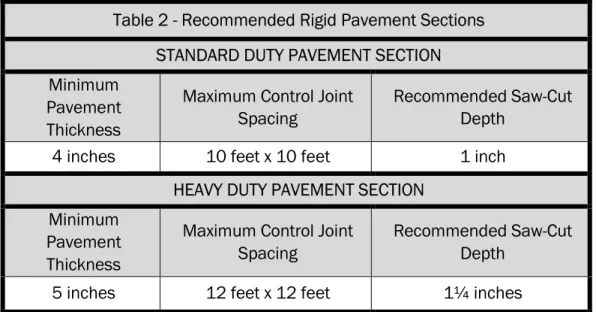
Our recommendations for slab thickness for the concrete pavement are based on the subgrade soils being densified to 98 percent of the Modified Proctor test method (ASTM D-1557), employment of a design modulus of subgrade reaction (k) equal to 100 pounds per cubic inch, and an assumed 20-year design life. We recommend using the designs shown for concrete (rigid) pavement sections on
Table 2 - Recommended Rigid Pavement Sections STANDARD DUTY PAVEMENT SECTION Minimum
Pavement Thickness
Maximum Control Joint Spacing
Recommended Saw-Cut Depth
4 inches 10 feet x 10 feet 1 inch
HEAVY DUTY PAVEMENT SECTION Minimum
Pavement Thickness
Maximum Control Joint Spacing
Recommended Saw-Cut Depth
5 inches 12 feet x 12 feet 1¼ inches
We recommend using concrete with a minimum 28-day compressive strength of 4,000 pounds per square inch (psi) and a minimum 28-day flexural strength
(modulus of rupture) of at least 600 psi, based on 3rd point loading of concrete
beam test samples. Layout of the saw cut control joints should form square panels, and the depth of saw cut joint should be ¼ of the concrete slab thickness. The joints should be sawed within six hours of concrete placement or as soon as the concrete has developed sufficient strength to support workers and equipment.
We recommend allowing NOVA to review and comment on the final concrete pavement design, including section and joint details (type of joints, joint spacing, etc.), prior to the start of construction. For further details on concrete pavement construction, please reference the “Guide to Jointing on Non-Reinforced Concrete Pavements” published by the Florida Concrete and Products Associates, Inc. (ACPA), and “Building Quality Concrete Parking Areas”, published by the Portland Cement Association.
7.0
CONSTRUCTION OBSERVATIONS
7.1 SHALLOW FOUNDATIONS
Foundation excavations should be level and free of debris, ponded water, mud, and loose, frozen or water-softened soils. All foundation excavations should be evaluated by a NOVA geotechnical engineer prior to reinforcing steel placement to observe foundation subgrade preparation and assess bearing pressure capacity. Due to variable site subsurface and construction conditions, some adjustments in isolated foundation bearing pressures, depth of foundations or undercutting and replacement with controlled structural fill may be necessary.
7.2 PAVEMENTS
The recommended pavement section should utilize materials and be constructed in accordance with applicable FDOT specifications and specific project requirements. Also, NOVA should be retained during construction to confirm subgrade conditions are as anticipated and that the construction process is as required by the contract documents
7.3 SUBGRADE
Once site grading is completed, the subgrade may be exposed to adverse construction activities and weather conditions. The subgrade should be well-drained to prevent the accumulation of water. If the exposed subgrade becomes saturated or frozen, the NOVA geotechnical engineer should be consulted.
Scale: Not To Scale PROJECT LOCATION MAP
Date Drawn: September 18, 2019 Jenks Avenue Commercial Development Additional Borings
Drawn By: J. Prout Panama City, Bay County, Florida
17612 Ashley Drive Panama City Beach, Florida 32413
Base map provided by Google Earth
33 41 08 0 33 41 09 0 33 41 10 0 33 41 11 0 33 41 12 0 33 41 13 0 33 41 14 0 33 41 15 0 33 41 16 0 33 41 17 0 33 41 18 0 33 41 09 0 33 41 10 0 33 41 11 0 33 41 12 0 33 41 13 0 33 41 14 0 33 41 15 0 33 41 16 0 33 41 17 0 33 41 18 0 33 41 19 0
628820 628830 628840 628850 628860 628870 628880 628890 628900 628910 628920 628930 628940 628950 628960 628970 628980
628820 628830 628840 628850 628860 628870 628880 628890 628900 628910 628920 628930 628940 628950 628960 628970 628980 628990
30° 11' 43'' N 30° 11' 43'' N
30° 11' 39'' N
85 ° 3 9' 4 2' ' W
30° 11' 39'' N
85 ° 3 9' 3 6' ' W N
Map projection: Web Mercator Corner coordinates: WGS84 Edge tics: UTM Zone 16N WGS84
0 35 70 140 210Feet
0 10 20 40 60Meters
Map Scale: 1:781 if printed on A landscape (11" x 8.5") sheet.
Soil Map may not be valid at this scale.
MAP LEGEND MAP INFORMATION
Area of Interest (AOI)
Area of Interest (AOI)
Soils
Soil Map Unit Polygons Soil Map Unit Lines Soil Map Unit Points
Special Point Features
Blowout Borrow Pit Clay Spot Closed Depression Gravel Pit Gravelly Spot Landfill Lava Flow Marsh or swamp Mine or Quarry Miscellaneous Water Perennial Water Rock Outcrop Saline Spot Sandy Spot Severely Eroded Spot Sinkhole
Slide or Slip Sodic Spot
Spoil Area Stony Spot Very Stony Spot Wet Spot Other
Special Line Features
Water Features
Streams and Canals
Transportation Rails Interstate Highways US Routes Major Roads Local Roads Background Aerial Photography
The soil surveys that comprise your AOI were mapped at 1:20,000.
Warning: Soil Map may not be valid at this scale.
Enlargement of maps beyond the scale of mapping can cause misunderstanding of the detail of mapping and accuracy of soil line placement. The maps do not show the small areas of contrasting soils that could have been shown at a more detailed scale.
Please rely on the bar scale on each map sheet for map measurements.
Source of Map: Natural Resources Conservation Service Web Soil Survey URL:
Coordinate System: Web Mercator (EPSG:3857)
Maps from the Web Soil Survey are based on the Web Mercator projection, which preserves direction and shape but distorts distance and area. A projection that preserves area, such as the Albers equal-area conic projection, should be used if more accurate calculations of distance or area are required.
This product is generated from the USDA-NRCS certified data as of the version date(s) listed below.
Soil Survey Area: Bay County, Florida Survey Area Data: Version 19, Sep 16, 2019
Soil map units are labeled (as space allows) for map scales 1:50,000 or larger.
Date(s) aerial images were photographed: Jan 18, 2015—Mar 7, 2015
The orthophoto or other base map on which the soil lines were compiled and digitized probably differs from the background imagery displayed on these maps. As a result, some minor shifting of map unit boundaries may be evident.
Map Unit Legend
Map Unit Symbol Map Unit Name Acres in AOI Percent of AOI
13 Leon sand, 0 to 2 percent slopes
1.0 36.7%
22 Pamlico-Dorovan complex 1.7 63.3%
Totals for Area of Interest 2.7 100.0%
Natural Resources Conservation Service
Web Soil Survey National Cooperative Soil Survey
11/4/2019 Page 3 of 3
Scale: Not To Scale BORING LOCATION PLAN
Date Drawn: November 4, 2019 Jenks Avenue Commercial Development Additional Borings
Drawn By: J. Prout Panama City, Bay County, Florida
17612 Ashley Drive Panama City Beach, Florida 32413 850.249.NOVA(6682) ♦ 850.249.6683
LEGEND
Hand Auger Boring Locations (HA-1 through HA-3)
25’ SPT Boring Location (B-3)
Base map provided by Mr. Bradley Bromlow
HA-1 HA-2
HA-3 B-3
Medium Stiff
FINE-GRAINED
SOILS
50%
or
more
passes
the
No.
200
sieve*
COARSE-GRAINED
SOILS
More
than
50%
retained
on
the
the
No.
200
Grey to light brown slightly silty fine-grained SAND (SP-SM)
Boring Terminated at 5 feet
Grap
hi
c
10 20 30 40 50 60 70 80 90
PL LL
Gro
undwa
ter Moisture Content (%)
Samp
le
Type
DRILLED BY: K. Selle
LOCATION: See Boring Location Plan ELEVATION: Existing Grade
Material Description
Fines Content (%)
PROJECT LOCATION: Panama City, Bay County, Florida
LOGGED BY: J. Prout
Th is inform ation pe rtains o nly t o th is bo ring and sho uld n ot be inte rpre te d as be ing indi cative of th e site .
Organic Content (%) N-Value (Blows per Foot)
N-Va
lue
INITIAL GW DEPTH: 4.3 feet
Dept h (fee t) 0 5 Eleva tion Note:
DRILLING METHOD: Hand Auger DATE: 10/25/2019
ESHGW DEPTH: 3.3 feet
TEST BORING
RECORD
Grey/light grey to grey/dark grey slightly silty fine-grained SAND (SP-SM)
Boring Terminated at 5 feet
Grap
hi
c
10 20 30 40 50 60 70 80 90
PL LL
Gro
undwa
ter Moisture Content (%)
Samp
le
Type
DRILLED BY: K. Selle
LOCATION: See Boring Location Plan ELEVATION: Existing Grade
Material Description
Fines Content (%)
PROJECT LOCATION: Panama City, Bay County, Florida
LOGGED BY: J. Prout
Th is inform ation pe rtains o nly t o th is bo ring and sho uld n ot be inte rpre te d as be ing indi cative of th e site .
Organic Content (%) N-Value (Blows per Foot)
N-Va
lue
INITIAL GW DEPTH: 3.8 feet
Dept h (fee t) 0 5 Eleva tion Note:
DRILLING METHOD: Hand Auger DATE: 10/25/2019
ESHGW DEPTH: 2.8 feet
TEST BORING
RECORD
Grey/dark grey slightly silty fine-grained SAND (SP-SM)
Dark grey silty fine-grained SAND with some organics - organic silt (SM)
Boring Terminated at 3 feet
Grap
hi
c
10 20 30 40 50 60 70 80 90
PL LL
Gro
undwa
ter Moisture Content (%)
Samp
le
Type
DRILLED BY: K. Selle
LOCATION: See Boring Location Plan ELEVATION: Existing Grade
Material Description
Fines Content (%)
PROJECT LOCATION: Panama City, Bay County, Florida
LOGGED BY: J. Prout
Th is inform ation pe rtains o nly t o th is bo ring and sho uld n ot be inte rpre te d as be ing indi cative of th e site .
Organic Content (%) N-Value (Blows per Foot)
N-Va
lue
INITIAL GW DEPTH: 1.6 feet
Dept h (fee t) 0 5 Eleva tion Note:
DRILLING METHOD: Hand Auger DATE: 10/25/2019
ESHGW DEPTH: 0.6 feet
TEST BORING
RECORD
Loose light brown slightly silty fine-grained SAND (SP-SM)
Medium dense dark grey slightly silty fine-grained SAND with few organics - organic silt (SP-SM) Medium dense grey/dark grey fine-grained SAND
(SP)
Medium dense dark grey silty fine-grained SAND with many organics - organic silt and wood (SM)
Loose grey fine-grained SAND (SP)
Loose to medium dense grey slightly clayey fine-grained SAND (SP-SC)
Medium dense grey fine-grained SAND (SP) Boring Terminated at 25 feet
5 13 12 22 10 12 5 23 Grap hi c
10 20 30 40 50 60 70 80 90
PL LL
Gro
undwa
ter Moisture Content (%)
Samp
le
Type
DRILLED BY: J. Governale
LOCATION: See Boring Location Plan ELEVATION: Existing Grade
Material Description
Fines Content (%)
PROJECT LOCATION: Panama City, Bay County, Florida
LOGGED BY: J. Prout
Th is inform ation pe rtains o nly t o th is bo ring and sho uld n ot be inte rpre te d as be ing indi cative of th e site .
Organic Content (%) N-Value (Blows per Foot)
N-Va
lue
INITIAL GW DEPTH: 1.5 feet
Dept h (fee t) 0 5 10 15 20 25 Eleva tion Note:
DRILLING METHOD: Mud Rotary DATE: 11/1/2019
ESHGW DEPTH:
TEST BORING
RECORD
B-3
Jenks Avenue Commercial Development Additional Borings Panama City, Bay County, Florida
NOVA Project Number 10111-2019176
Boring
Number Sample Depth Natural Moisture (%)
Percent (%) Passing Sieve #200
Organic Content (%)
USCS Soil Classification
HA-2 1.0’ - 2.0’ 7 7.0 --- SP-SM
HA-3 0.0’ - 2.0’ 21 6.5 --- SP-SM
QUALIFICATIONS OF RECOMMENDATIONS
The findings, conclusions and recommendations presented in this report represent our professional opinions concerning subsurface conditions at the site. The opinions presented are relative to the dates of our site work and should not be relied on to represent conditions at later dates or at locations not explored. The opinions included herein are based on information provided to us, the data obtained at specific locations during the study, and our previous experience. If additional information becomes available which might impact our geotechnical opinions, it will be necessary for NOVA to review the information, re-assess the potential concerns, and re-evaluate our conclusions and recommendations.
Regardless of the thoroughness of a geotechnical exploration, there is the possibility that conditions between borings may differ from those encountered at specific boring locations, that conditions are not as anticipated by the designers and/or the contractors, or that either natural events or the construction process has altered the subsurface conditions. These variations are an inherent risk associated with subsurface conditions in this region and the approximate methods used to obtain the data. These variations may not be apparent until construction. The professional opinions presented in this report are not final. Field observations and foundation installation monitoring by the geotechnical engineer, as well as soil density testing and other quality assurance functions associated with site earthwork and foundation construction, are an extension of this report. Therefore, NOVA should be retained by the owner to observe all earthwork and foundation construction to confirm that the conditions anticipated in this study actually exist, and to finalize or amend our conclusions and recommendations. NOVA is not responsible or liable for the conclusions and recommendations presented in this report if NOVA does not perform these observation and testing services.
This report is intended for the sole use of Mr. Bradley Bromlow only. The scope of work performed during this study was developed for purposes specifically intended by Mr. Bradley Bromlow only and may not satisfy other users’ requirements. Use of this report or the findings, conclusions or recommendations by others will be at the sole risk of the user. NOVA is not responsible or liable for the interpretation by others of the data in this report, nor their conclusions, recommendations or opinions.
Our professional services have been performed, our findings obtained, our conclusions derived and our recommendations prepared in accordance with generally accepted geotechnical engineering principles and practices in the State of Florida. This warranty is in lieu of all other statements or warranties, either expressed or implied.
Geotechnical-Engineering Report
Geotechnical Services Are Performed for Specific Purposes, Persons, and Projects
Geotechnical engineers structure their services to meet the specific needs of their clients. A geotechnical-engineering study conducted for a civil engineer may not fulfill the needs of a constructor — a construction contractor — or even another civil engineer. Because each geotechnical- engineering study is unique, each geotechnical-engineering report is unique, prepared solely for the client. No one except you should rely on this geotechnical-engineering report without first conferring with the geotechnical engineer who prepared it. And no one — not even you — should apply this report for any purpose or project except the one originally contemplated.
Read the Full Report
Serious problems have occurred because those relying on a geotechnical-engineering report did not read it all. Do not rely on an executive summary. Do not read selected elements only.
Geotechnical Engineers Base Each Report on a Unique Set of Project-Specific Factors
Geotechnical engineers consider many unique, project-specific factors when establishing the scope of a study. Typical factors include: the client’s goals, objectives, and risk-management preferences; the general nature of the structure involved, its size, and configuration; the location of the structure on the site; and other planned or existing site improvements, such as access roads, parking lots, and underground utilities. Unless the geotechnical engineer who conducted the study specifically indicates otherwise, do not rely on a geotechnical-engineering report that was:
• not prepared for you; • not prepared for your project;
• not prepared for the specific site explored; or
• completed before important project changes were made. Typical changes that can erode the reliability of an existing geotechnical-engineering report include those that affect: • the function of the proposed structure, as when it’s changed
from a parking garage to an office building, or from a light-industrial plant to a refrigerated warehouse;
• the elevation, configuration, location, orientation, or weight of the proposed structure;
• the composition of the design team; or • project ownership.
As a general rule, always inform your geotechnical engineer of project changes—even minor ones—and request an
assessment of their impact. Geotechnical engineers cannot accept responsibility or liability for problems that occur because their reports do not consider developments of which they were not informed.
Subsurface Conditions Can Change
A geotechnical-engineering report is based on conditions that existed at the time the geotechnical engineer performed the study. Do not rely on a geotechnical-engineering report whose adequacy may have been affected by: the passage of time; man-made events, such as construction on or adjacent to the site; or natural events, such as floods, droughts, earthquakes, or groundwater fluctuations. Contact the geotechnical engineer before applying this report to determine if it is still reliable. A minor amount of additional testing or analysis could prevent major problems.
Most Geotechnical Findings Are Professional Opinions
Site exploration identifies subsurface conditions only at those points where subsurface tests are conducted or samples are taken. Geotechnical engineers review field and laboratory data and then apply their professional judgment to render an opinion about subsurface conditions throughout the site. Actual subsurface conditions may differ — sometimes significantly — from those indicated in your report. Retaining the geotechnical engineer who developed your report to provide geotechnical-construction observation is the most effective method of managing the risks associated with unanticipated conditions.
A Report’s Recommendations Are Not Final
Do not overrely on the confirmation-dependent
recommendations included in your report. Confirmation-dependent recommendations are not final, because geotechnical engineers develop them principally from judgment and opinion. Geotechnical engineers can finalize their recommendations only by observing actual subsurface conditions revealed during construction. The geotechnical engineer who developed your report cannot assume
responsibility or liability for the report’s confirmation-dependent recommendations if that engineer does not perform the
geotechnical-construction observation required to confirm the recommendations’ applicability.
A Geotechnical-Engineering Report Is Subject to Misinterpretation
Other design-team members’ misinterpretation of geotechnical-engineering reports has resulted in costly
Important Information about This
Subsurface problems are a principal cause of construction delays, cost overruns, claims, and disputes. While you cannot eliminate all such risks, you can manage them. The following information is provided to help.
engineer to review pertinent elements of the design team’s plans and specifications. Constructors can also misinterpret a geotechnical-engineering report. Confront that risk by having your geotechnical engineer participate in prebid and preconstruction conferences, and by providing geotechnical construction observation.
Do Not Redraw the Engineer’s Logs
Geotechnical engineers prepare final boring and testing logs based upon their interpretation of field logs and laboratory data. To prevent errors or omissions, the logs included in a geotechnical-engineering report should never be redrawn for inclusion in architectural or other design drawings. Only photographic or electronic reproduction is acceptable, but recognize that separating logs from the report can elevate risk.
Give Constructors a Complete Report and Guidance
Some owners and design professionals mistakenly believe they can make constructors liable for unanticipated subsurface conditions by limiting what they provide for bid preparation. To help prevent costly problems, give constructors the complete geotechnical-engineering report, but preface it with a clearly written letter of transmittal. In that letter, advise constructors that the report was not prepared for purposes of bid development and that the report’s accuracy is limited; encourage them to confer with the geotechnical engineer who prepared the report (a modest fee may be required) and/ or to conduct additional study to obtain the specific types of information they need or prefer. A prebid conference can also be valuable. Be sure constructors have sufficient time to perform additional study. Only then might you be in a position to give constructors the best information available to you, while requiring them to at least share some of the financial responsibilities stemming from unanticipated conditions.
Read Responsibility Provisions Closely
Some clients, design professionals, and constructors fail to recognize that geotechnical engineering is far less exact than other engineering disciplines. This lack of understanding has created unrealistic expectations that have led to
disappointments, claims, and disputes. To help reduce the risk of such outcomes, geotechnical engineers commonly include a variety of explanatory provisions in their reports. Sometimes labeled “limitations,” many of these provisions indicate where geotechnical engineers’ responsibilities begin and end, to help
Environmental Concerns Are Not Covered
The equipment, techniques, and personnel used to perform an environmental study differ significantly from those used to perform a geotechnical study. For that reason, a geotechnical-engineering report does not usually relate any environmental findings, conclusions, or recommendations; e.g., about the likelihood of encountering underground storage tanks or regulated contaminants. Unanticipated environmental problems have led to numerous project failures. If you have not yet obtained your own environmental information,
ask your geotechnical consultant for risk-management guidance. Do not rely on an environmental report prepared for someone else.
Obtain Professional Assistance To Deal with Mold
Diverse strategies can be applied during building design, construction, operation, and maintenance to prevent
significant amounts of mold from growing on indoor surfaces. To be effective, all such strategies should be devised for the express purpose of mold prevention, integrated into a comprehensive plan, and executed with diligent oversight by a professional mold-prevention consultant. Because just a small amount of water or moisture can lead to the development of severe mold infestations, many mold- prevention strategies focus on keeping building surfaces dry. While groundwater, water infiltration, and similar issues may have been addressed as part of the geotechnical- engineering study whose findings are conveyed in this report, the geotechnical engineer in charge of this project is not a mold prevention consultant; none of the services performed in connection with the geotechnical engineer’s study were designed or conducted for the purpose of mold prevention. Proper implementation of the recommendations conveyed in this report will not of itself be sufficient to prevent mold from growing in or on the structure involved.
Rely, on Your GBC-Member Geotechnical Engineer for Additional Assistance
Membership in the Geotechnical Business Council of the Geoprofessional Business Association exposes geotechnical engineers to a wide array of risk-confrontation techniques that can be of genuine benefit for everyone involved with a construction project. Confer with you GBC-Member geotechnical engineer for more information.
8811 Colesville Road/Suite G106, Silver Spring, MD 20910 Telephone: 301/565-2733 Facsimile: 301/589-2017 e-mail: [email protected] www.geoprofessional.org
Copyright 2015 by Geoprofessional Business Association (GBA). Duplication, reproduction, or copying of this document, or its contents, in whole or in part, by any means whatsoever, is strictly prohibited, except with GBA’s specific written permission. Excerpting, quoting, or otherwise extracting wording from this document
is permitted only with the express written permission of GBA, and only for purposes of scholarly research or book review. Only members of GBA may use this document as a complement to or as an element of a geotechnical-engineering report. Any other firm, individual, or other entity that so uses this document without