Doi10.15802/stp2014/30833 © O. O. Hololobova, V. I. Havryliuk, M. O. Kovryhin, S. YU. Buriak, 2014
АВТОМАТИЗОВАНІ СИСТЕМИ УПРАВЛІННЯ
НА ТРАНСПОРТІ
UDC 656.259.2: 621.315
O. O. HOLOLOBOVA
1*, V. I. HAVRYLIUK
2, M. O. KOVRYHIN
3, S. YU. BURIAK
41*Dep. «Automation, Telemechanics and Communications», Dnipropetrovsk National University of Railway Transport
named after Academician V. Lazaryan, Lazaryan St. 2, Dnipropetrovsk, Ukraine, 49010, tel. +38 (056) 373 15 04, e-mail [email protected], ORCID 0000-0003-1857-8196
2Dep. «Automation, Telemechanics and Communications», Dnipropetrovsk National University of Railway Transport
named after Academician V. Lazaryan, Lazaryan St. 2, Dnipropetrovsk, Ukraine, 49010, tel. +38 (056) 373 15 04, e-mail [email protected], ORCID 0000-0001-9954-4478
3Dep. «Automation, Telemechanics and Communications», Dnipropetrovsk National University of Railway Transport
named after Academician V. Lazaryan, Lazaryan St. 2, Dnipropetrovsk, Ukraine, 49010, tel. +38 (056) 373 15 04
4Dep. «Automation, Telemechanics and Communications», Dnipropetrovsk National University of Railway Transport
named after Academician V. Lazaryan, Lazaryan St. 2, Dnipropetrovsk, Ukraine, 49010, tel.+38 (056) 373 15 04, e-mail [email protected], ORCID 0000-0002-8251-785х
STUDY OF TRANSMISSION LINES EFFECT ON THE SYSTEM
OPERATIONON OF CONTINUOUS AUTOMATIC CAB SIGNALLING
Purpose. To conductan effect research of the electromagnetic field of high-voltage transmission lines (HVTL) (750 kV, 50 Hz) on the track circuits and continuous automatic cab signalling (CACS) with a signal current of 50 Hz in the areas of convergence and intersection with the transmission lines and to propose possible methods to improve noise immunity of CACS. Methodology. The measurements were performed both by means of car-laboratory and directly on rail lines. During the study the electric field strength in the range of industrial frequency directly under the transmis-sion lines and at the distance from it to the railway lines was measured, as well as the time dependence of CACS codes with signal current frequency of 50 Hz directly under the transmission lines and at a distance from it in the absence of the train and its passing. Findings. The root causes analysis of CACS faults and failures was carried out. The effect of the electromagnetic field of high-voltage transmission lines (750 kV, 50 Hz) on the track circuit and CACS with signal current of 50 Hz in the areas of convergence and intersection with the transmission line was investigated. Possible methods to improve noise immunity of CACS were considered. Originality. The effect research of transmission lines (750 kV) on the operation of the automatic cab signalling on spans Prishib-Burchatsk and Privolnoye-Yelizarovo, Prid-neprovsk railway in places of oblique railroads crossing and transmission lines (750 kV, 50 Hz) was conducted. Elec-tric field strength in the range of industrial frequency directly under the transmission lines and at a distance from it to the railway line, as well as the time dependences of ALSN codes with signal current frequency of 50 Hz directly under the transmission lines and at a distance from it in the absence of the train and as its passing were measured. It was found that CACS codes in track circuits under transmission lines are strongly distorted, as strength measurements of electric field are shown, it can be explained by the electromagnetic field effect of transmission lines on track circuits. Practical value. Possible methods of CACS safety enhancement by improving the reliability of signaling from a track on the locomotive were considered.
Keywords: automatic cab signalling system; fault; failure; high-voltage transmission line
Introduction
Recently, in Ukraine there is an increase of train speeds, implementation of accelerated
Doi10.15802/stp2014/30833 © O. O. Hololobova, V. I. Havryliuk, M. O. Kovryhin, S. YU. Buriak, 2014 Fig. 1. Main reasons classification of faults and failures in ACS operation
Short-term faults and failures of continuous automatic cab signalling (CACS) are connected with a large number of reasons (Fig. 1) [7].
Natural destabilizing factors due to the design features of the track structure and functional char-acteristics of the system itself, can lead to the
Doi10.15802/stp2014/30833 © O. O. Hololobova, V. I. Havryliuk, M. O. Kovryhin, S. YU. Buriak, 2014 Furthermore, there are some protective measures:
– accelerated and preliminary signalling to the track circuits, decoding by a decoder the yellow light signal with red one after the second arrival, matching the washer starting in the transmitter;
– fixation by a decoder the green light signals with an extra impulse during a time delay of con-trol relay in code combinations entry (CCE), the use of code transmitters with a shorter duration of code combinations - 1.6 sec. on the stations, the location of insulated joints in the transition curves of switches, and not on the main track [5].
External interferences in turn differ in the na-ture of impact. Impulsive noise consist of short current pulses, induced in the receiver coils of a locomotive. They have an arbitrary shape and their occurrence moment, amplitude and duration are absolutely sporadic. It is impossible to determine how often the pulses will follow in turn, there is no regularity in their intensity, shape and duration. Impulse noise effect on the electrical signals of cab signalling can lead to quantitative errors (including the received impulses) and quality impulse distor-tions. Nature of these noise depends on their sources (switch processes in the current collector, in the collectors of cars, converter istallations and other elements of the electrical circuit of the loco-motive may be as impulse noise), so the choice of the most effective fighting method is based on the analysis of their characteristics, which are deter-mined during research in those specific conditions in which signal transmission takes place.
In the harmonic noise occurence a certain regular-ity is defined, so protection against them is often con-structed on the frequency selection using electric fil-ters. They prevent effect of oscillations with a fre-quency different from the frefre-quency of the signal current of cab signalling on the receiving devices.
The percentage of faults caused by the transmis-sion line effect, in relation to the total number of repeated faults due to the blame of signal telephone and telegraph service (Sh) on the Prydneprovsk railway for the last 4 years is shown in Figure 2.
Purpose
Research conducting of the electromagnetic field effect of high-voltage transmission lines (750 kV, 50 Hz) on the track circuit and CACS with signal current of 50 Hz on the sections of approach and crossing with the transmission line and to propose possible methods to improve CACS noise immunity.
Analysis of faults in the CACS operation
An important task of traffic safety is to ensure trouble-free operation of automatic cab signalling.
A special place is the problem of protection against the effects of transmission lines (TL) on the sections with DC electric traction and diesel trac-tion when the cab signalling devices operate at a frequency of 50 Hz, and so the methods of fre-quency-division signalling and harmonic noise are not applicable [1].
% 15
% 11
% 8
% 6
0 50 100 150 200 250 300 350 400
2010 2011 2012 2013
The total number of failures due to the service Sh fault, of them: transmission lines effect
Doi10.15802/stp2014/30833 © O. O. Hololobova, V. I. Havryliuk, M. O. Kovryhin, S. YU. Buriak, 2014 There are two ways of solving this problem.
The first method is external in relation to the sys-tem and represents the maximum exclusion of the transmission line effect by shielding the current-carrying elements, or electric circuits use with an-tiphase protection currents which flows in the vari-ous circuits in order to reduce effects of electro-magnetic noise of the transmission lines on the receiver coils.
The second method of protection is intersystem method. It is a necessity to develop such a mecha-nism or algorithm of the system operation that transmits traffic lights readings on the locomotive, so that even small changes in the shape, amplitude, duration of pauses and intervals are excluded and do not result in the faults of codes.
One should determine what the most effective method is. To do this we will carry out the analysis of the work and functioning of the automatic cab signalling system under the transmission lines ef-fect. In accordance with the analysis of noise im-munity under the effect of high electromagnetic fields one can judge about advantages and disad-vantages of a particular protection method.
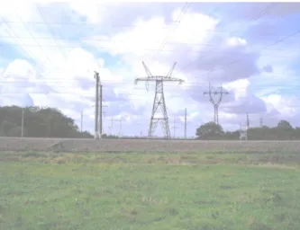
Fig. 3. Transmission lines crossing the railway track Ttransmission lines noise have sinusoidal nature and occur in places of transmission lines approach with the railway as crossings or in the form of mu-tual parallel arrangement [14]. Zone of interference factor is small (approximately 30-40 m on each side from an axis of the transmission lines). However, on a number of roads faults in the vicinity of the inter-section with the transmission lines are significant. Lines that are parallel to the railways, are usually low-power, that is why they do not require a special protection methods. But the lines crossing the track
at different angle, have a fundamental importance on the ACS receiving system.
The transmission lines effect on ACS receiving devices depends on many factors. The most impor-tant is: angle of crossing of transmission lines of the railway line, suspension type of wires on the support, the phase currents and their asymmetry, asymmetry of locomotive receiver coils relatively to the wires of the influencing line and others [10].
Effective protection measures are necessary to reduce the level of noise from transmission lines. To some extent, this protection is ensured with ef-ficiency of automatic gain control (AGC). AGC is required to avoid distortion of the receiving code signals [4]. Current level in the rails under the re-ceiver coils while the locomotive moves may in-crease more than 20 times, depending on the length of the rail line. The signal amplitude at the output of the filter increases during the impulse and expo-nential decrease during the pause. If the sensitivity of the locomotive receiver remained unchanged, then with an increase of the input signal would oc-cur pulse stretching and shortening of pause, as at invariable time constant of the transition process in this case the wavefront would decrease and the recession would increase the amplitude of the sig-nal from the steady-state value to the threshold of sensitivity.
Fig. 4. Time dependence of the amplifier sensitivity recovery
With the help of AGC sensitivity of a locomo-tive receiver is reduced, it promotes undistorted reception of code signals.
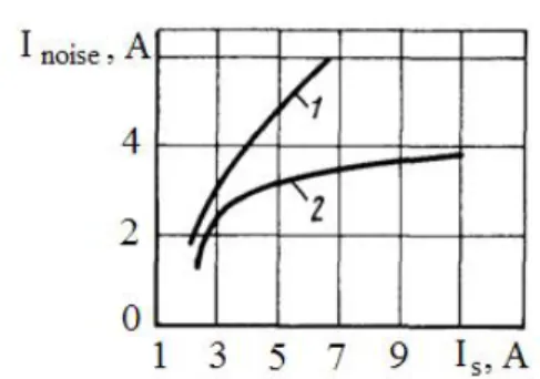
Doi10.15802/stp2014/30833 © O. O. Hololobova, V. I. Havryliuk, M. O. Kovryhin, S. YU. Buriak, 2014 Fig. 5. Efficiency graphics and anti-interference
features of the AGC:
1 – maximum value of interference current for provision of normal ACS operation during the noise in phase with the
desired signal; 2 – maximum value of interference current for provision of normal ACS operation during the noise
influemece in antiphase
Another way to improve the reliability of the ACS operation is the development of protective devices (Fig. 6) [9]. The proposed device allows preventing the effects of the noise influence from transmission lines on the ACS work regardless of the train speed. This greatly improves the operation reliability of the ACS devices.
Fig. 6. Protection equipment of operation devices of automatic cab signalling from transmission lines noise: 1 – plus and 2 – minus poles of energy source; 3 – equivalent relay; 4 – frontline contacts of code presence relay; 5 – third counter; 6 – green light relay; 7 – red and yellow light relay;
8 – resistor; 9 – condenser; 10 – contact of impulse relay;
11 – reversal repeater of impulse relay; 12 – spark quenching diode; 13 – spark quenching resistor; 14 – contact of reversal
repeater; 15 – additional resistor; 16 – additional diode;
17 – the first additional capacitor; 18 – the second additional capacitor; 19 – the third additional capacitor; 20 – the fourth additional capacitor; 21 – the fifth additional capacitor;
22 – speed gauge; 23 – the first, 24 – the second, 25 – the third and 26 – the fourth contacts of speed gauge
In addition, there are other ways to reduce the transmission lines effect: increasing the height of the suspension and reducing the distance between the wires of transmission lines at the point of inter-section, arranging of special, closed and suspended or laid on the ground stubs, which are served with the current, frequency of 50 Hz, the phase-shifted with respect to the current of induced noise, com-pensation of current interference by specially laid on the locomotive circuit and increase the signal current at the intersection.
Since the effect of transmission lines can be conditionally subdivided into direct and indirect, it is necessary to take into account that most of the protection methods grade the direct influence of the transmission lines magnetic field on ACS coils. But studies show [13] that the noise level is deter-mined mainly by an indirect effect, i.e. it is a con-sequence of the guidance in the electromagnetic mass (frame, bogies, body and so on.) the locomo-tive of eddy current, their magnetic field directly affects on the receiver coils. Therefore, the task of protective measures development remains vital.
Methodology
Doi10.15802/stp2014/30833 © O. O. Hololobova, V. I. Havryliuk, M. O. Kovryhin, S. YU. Buriak, 2014 Electric Codes of Ukraine regulate norms of
rail-way tracks crossing (item 2.5.207-2.5.211) [6, 11]: – crossing angle of HVL with electrified rail-ways or subject to railway electrification, as well as the crossing angle of 750 kW with the railways of general use should be approximately 90°, but not less than 40°;
– for the non-electrified railways distance from the wire to the rail head in the normal mode of the HVL vertically should be at least 7.5 m - 20 m at a voltage of 110 kW to 750 kW properly;
– span of railroad crossing limited with spun poles (Fig. 7).
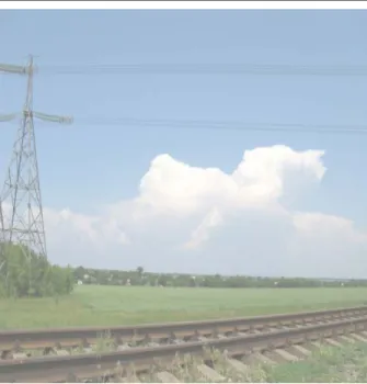
Let us take for the research two spans on Pryd-niprovsk railway stations on the crossing sections with the transmission line 750 kW: Prishib-Bur-chatsk, Zaporizhzhia region (Figure 8) and distilled Privolnoye–Yelizarovo (Figure 9).
Fig. 7. Scheme of the span crossing with the railway Span Prishib-Burchatsk is electrified with di-rect current, measurements were carried out with system "Control" on the basis of a car-laboratory of Prydniprovsk signal telephone and telegraph service.
Fig. 8. Span Prishib-Byrchak
Fig. 9. Span Privolnoye–Eylizarovo
On the span Privolnoye Eylizarovo the con-tinuous welded railway track with self-contained traction. The length of the track circuit between signal points 1 and 18, where there is a crossing section with the transmission lines, 839 m.
The electromagnetic emission meter levels P3-41, ampervoltmetr TS-43-80 («C-4380») with an internal resistance of 0.06 ohms, Rogowski coil were used for the research.
The following methods for measuring the ACL signal current in rails are presented [12]:
1) Continuous current measurement sent to the RC during the check-up instead the impulse. Do this requires to shunt transmitter relay contact with a jumper for temporary sending the continuous current;
2) Measurement of pulse current. During this prosess one shunt a track circuit at the input end by an ampervoltmeters with a special driver provided with an outer head or by ammeters with the inter-nal resistance not more than 0.06-0.08 ohms TS-56 («C-56»), TS-760 («C-760»), TS-4380 («C-4380»), at a scale 6A );
rec-Doi10.15802/stp2014/30833 © O. O. Hololobova, V. I. Havryliuk, M. O. Kovryhin, S. YU. Buriak, 2014 ommended to use an ammeter TS-4380 («C-4380»),
with a scale of 0-1.5 A with a resistance of 0.32 ohms;
4) Current measurement with track circuit shunting with a test shunt. This method finds ap-plication in the absence of an ammeter with low input impedance. Voltage on a shunt is measured and divided on its resistance (0.06 ohms), the re-sulting value is current of locomotive signaling.
In the research of the span Privolnoye-Eylizarovo a second method using an ammeter TS-4380 («C-4380»), with an internal resistance of 0.06 ohms was applied. Using probes the track cir-cuit was shunted for a short time. On one of the probes a Rogowski coil was put on, which was connected to the analog-to-digital converter. Wir-ing diagram is presented in Figure 10. In addition, since the interfering effect area of transmission lines is approximately 30-40 m, measurements of a level of electromagnetic field emission were con-ducted by means of unit RR-41 («PP-41») at a given distance, a height of about 20 cm above the railhead elevation (taking into account the height of the receiver coilws) and at a height of about 2.5 m.
Fig. 10. Wiring diagram for the organization of measurements:
MU – measurement unit TS-4380 («С-4380»); RC – Rogowski coil; АDC – analog-to-digital converter; R – relay end of track cicuit; S – supply end of track circuit
Findings
Measurements results of signal current of the green light code (Z) with a car-laboratory of signal telephone and telegraph department on Prydni-provsk railway are presented in Figure 11.
As in the Figure, noise in the coils, induced by transmission lines of 750 kV, are so strong that code availability [3] is hardly discerned. Noise fill
short pause, long interval between codes and su-perimposed on impulses of code. The magnitude of the greatest noise reaches more than 1 W, which is about equivalent to a disturbing current in the rails, value 6 A.
Fig. 11. Signal current code Z
The measurements results of the signal current of yellow light code (W) with a car-laboratory are presented in Figure 12.
Fig. 12. Signal current code W
As in Figure noise in locomotive coils distort three consecutive cycles W. The magnitude of the greatest interference reaches about 1 W that is also approximately equivalent to a disturbing current in rails 6 A as in the previous measurement. In these both cases, the signal through the ADC was taken directly from the locomotive coils, so we observe both direct and indirect effects of transmission lines.
The measurements results of the signal current, code W (a tested section of a track is located in front of preinput signal point) are presented in Fig. 13.
measure-Doi10.15802/stp2014/30833 © O. O. Hololobova, V. I. Havryliuk, M. O. Kovryhin, S. YU. Buriak, 2014 ments, the average position of the instrument
indi-cator TS-4380 («С-4380») at steady-state oscilla-tions under the influence of the measured current has shown the current rate in rails of 8 A. On the given section the current signal level is too high due to the need for protection against noise, in-duced with HTL (see Fig. 12). In this case, we can talk about research of direct transmission lines im-pact, as readings were taken directly from the track circuit without the presence of the rolling stock. Consequently significant disruptions in the ACS codes on this section are caused by the indirect effect of the HVL.
Fig. 13. Signal current code W
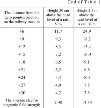
The results of measurements with the RR-41 («PP-41») are presented in Table 1.
Table 1 The electromagnetic field strength in the zone of
in-terference effect of transmission line
The distance from the zero point-projection on the railway track m
Height 20 cm above the head
level of a rail, V/m
Height 2.5 m above the head level of
a rail, V/m
-30 4,4 7,4
-27 5,3 8,0
-24 5,7 8,3
-21 6,1 8,5
-18 6,7 8,8
-15 8,5 9,6
-12 8,8 12,4
-9 9,9 17,9
-6 11,5 24,8
-3 12,3 27,0
0 12,6 35,0
+3 12,0 26,0
End of Table 1
The distance from the zero point-projection on the railway track m
Height 20 cm above the head
level of a rail, V/m
Height 2.5 m above the head level of
a rail, V/m
+6 11,7 24,9
+9 9,3 18,2
+12 8,3 13,4
+15 7,2 10,0
+18 6,5 9,1
+21 6,2 8,6
+24 5,4 8,0
+27 4,9 7,8
+30 4,2 7,6
The average
electro-magnetic field strength 7,98 14,35
The results of measurement with an instrument RR-41 («PP-41») are presented in the Table 1. The electromagnetic field strength at a height of 2.5 m is 2-3 times greater than at a height of 20 cm from the railhead elevation - height of receiver coil sus-pension.
Originality and practical value
The research of transmission line 750 kW effect on the operation of automatic cab signalling on spans Prishib-Burchatsk and Privolnoye-Yelizarovo Prydniprovsk railway in the places of oblique rail-road crossing and transmission line of 750 kW, 50 Hz were conducted. Measurements were made both by means of the car-laboratory and directly on rail lines. In the research course the electric field intensity in the range of industrial frequency directly under the transmission line and with distance from it along the railway, as well as the time dependences of CACS codes with signal current frequency of 50 Hz is directly under the transmission lines and with distance from it in the absence of the train and its passing were measured. It was found that CACS codes in rail circuits under the transmission lines are strongly distorted, which as shown by measure-ments of the electric field intensity can be explained by the influence of the electromagnetic field of the transmission line on the track circuits.
Doi10.15802/stp2014/30833 © O. O. Hololobova, V. I. Havryliuk, M. O. Kovryhin, S. YU. Buriak, 2014 Conclusions
Root causes analysis of the faults and failures in CACS was conducted. The effect of the elec-tromagnetic field of high-voltage transmission lines (750 kV, 50 Hz) on the track circuits and CACS with signal current of 50 Hz in the areas of convergence and intersection with the transmission line was studied.
The possible methods of increasing interference protection of CACS were considered.
LIST OF REFERENCE LINKS
1. Безнаритний, А. М. Аналіз стану пристроїв автоблокування, методів його обслуговування та контролю / А.М. Безнаритний, В. І. Гаври
-люк, О. О. Гололобова // Наука та прогрес трансп. Вісн. Дніпропетр. нац. ун-ту залізн.
трансп. – 2014. – № 1 (49). – С. 22–32.
2. Гаврилюк, В. І. Ймовірнісна модель впливу тягового струмунарейкові кола / В. І. Гаври
-люк, О. В. Завгородний // Інформац.-керуючі системиназалізничн. трансп. – 2010. – № 4. –
С. 73–76.
3. Гололобова, О. О. Математичне моделювання вхіднихпристроївсистемиавтоматичноїлоко
-мотивноїсигналізації / О. О. Гололобова // На
-ука та прогрес трансп. Вісн. Дніпропетр. нац.
ун-ту залізн. трансп. – 2014. – № 2 (50). –
С. 21–30.
4. Інструкція з технічного обслуговування локо
-мотивних пристроїв автоматичної локомотив
-ної сигналізації безперервного типу (АЛС)
і пристроїв контролю пильності машиніста на залізницяхУкраїни : ЦТ-ЦШ-0072. – К. : Укр
-залізниця, 2004. – 92 с.
5. Казаков, А. А. Автоблокировка, локомотивная сигнализацияиавтостопы : учеб. длятехнику
-мовж.-д. трансп. / А. А. Казаков, Е. А. Казаков. – 7-е изд., перераб. и доп. – М. : Транспорт, 1980. – 360 с.
6. Конструктивные параметры воздушныхлиний
электропередачи [Electronic resource] / Школа для электрика. – 2010–2014. – Available at:
http://electricalschool.info/main/vl/829-konstruktivnye-parametry-vozdushnykh.html. – Title from the screen. – Accessed : 08.06.2014.
7. Кошевий, С. В. Електромагнітні завади в ме
-жахрейковоїлініїіїхвпливнароботуавтома
-тичноїлокомотивноїсигналізації / С. В. Коше
-вий, М. С. Кошевий, М. М. Бабаєв // Інфор
-мац.-керуючісистеминазалізн. трансп. – 2008. – № 4. – С. 13.
8. Леонов, А. А. Техническое обслуживание
автоматической локомотивной сигнализации /
А. А. Леонов. – 5-еизд., перераб. идоп. – М. :
Транспорт, 1982. – 255 с.
9. Пат. 2475395 Россия, B61L25/02. Устройство защиты работы устройств автоматической ло
-комотивной сигнализации от помех линий
электропередач [Electronic resource] / Косола
-повА. М., ПолевойЮ. И. (Россия) ; заявитель ипатентовладелецГос. образоват. учреждение высшегопрофессион. образования «Самарский гос. ун-т путей сообщения». – Available at: http://www.findpatent.ru/patent/247/2475395.html. – Title from the screen. – Accessed: 08.06.2014. 10. Системыжелезнодорожнойавтоматикиителе
-механіки : учеб. для вузов / Ю. А. Кравцов,
В. Л. Нестеров, Г. Ф. Лекутаидр. – М. : Транс
-порт, 1996. – 400 с.
11. Правила устройства электроустановок Украи
-ны 2009 (по разделам) [Electronic resource] /
Охрана труда. – 2010-2012. – Available at: http://www.ohranatruda.in.ua/pages/5004/. – Title from the screen. – Accessed : 08.06.2014.
12. Электромагнитная совместимость устройств
автоматической локомотивной сигнализации
стяговойсетью [Electronic resource] / Централ.
науч. б-ка. – 2013. – Available at: http://www.0ck.ru/ transport/elektromagnitnaya_sovmestimost_ustro-jstv.html. – Title from the screen. – Accessed : 08.06.2014.
13. Railroad-Highway Grade Crossing Handbook - Revised Second Edition August [Electronic re-source] / U.S. Department of Transportation. Fed-eral Highway Administration. – 2007. – Available at: http://safety.fhwa.dot.gov/xings/com_roaduser/ 07010/sec04b.htm. – Title from the screen. – Ac-cessed : 08.06.2014.
Doi10.15802/stp2014/30833 © O. O. Hololobova, V. I. Havryliuk, M. O. Kovryhin, S. YU. Buriak, 2014
О
.
О
.
ГОЛОЛОБОВА
1*,
В
.
І
.
ГАВРИЛЮК
2,
М
.
О
.
КОВРИГІН
3,
С
.
Ю
.
БУРЯК
41*Каф. «Автоматика, телемеханікатазв’язок», Дніпропетровськийнаціональнийуніверситетзалізничноготранспорту іменіакадемікаВ. Лазаряна, вул. Лазаряна, 2, Дніпропетровськ, Україна, 49010, тел.+38 (056) 373 15 04,
ел. пошта [email protected], ORCID 0000-0003-1857-8196
2Каф. «Автоматика, телемеханікатазв’язок», Дніпропетровськийнаціональнийуніверситетзалізничноготранспорту іменіакадемікаВ. Лазаряна, вул. Лазаряна, 2, Дніпропетровськ, Україна, 49010, тел.+38 (056) 373 15 04,
ел. пошта [email protected], ORCID 0000-0001-9954-4478
3Каф. «Автоматика, телемеханікатазв’язок», Дніпропетровськийнаціональнийуніверситетзалізничноготранспорту іменіакадемікаВ. Лазаряна, вул. Лазаряна, 2, Дніпропетровськ, Україна, 49010, тел.+38 (056) 373 15 04
4Каф. «Автоматика, телемеханікатазв’язок», Дніпропетровськийнаціональнийуніверситетзалізничноготранспорту іменіакадемікаВ. Лазаряна, вул. Лазаряна, 2, Дніпропетровськ, Україна, 49010, тел.+38 (056) 373 15 04,
ел. пошта [email protected], ORCID 0000-0002-8251-785х
ДОСЛІДЖЕННЯ
ВПЛИВУ
ЛІНІЙ
ЕЛЕКТРОПЕРЕДАЧІ
НА
РОБОТУ
СИСТЕМИ
АВТОМАТИЧНОЇ
ЛОКОМОТИВНОЇ
СИГНАЛІЗАЦІЇ
НЕПЕРЕРВНОЇ
ДІЇ
Мета. Роботамаєзаметупроведеннядослідженнявпливуелектромагнітногополявисоковольтноїлінії електропередачі (ЛЕП) (750 кВ, 50 Гц) нарейковіколаіавтоматичнулокомотивнусигналізаціюнеперервної дії (АЛСH) зсигнальнимструмом 50 ГцнаділянкахзближенняіперетинузЛЕПтазапропонуватиможливі методи підвищення перешкодозахищеності АЛСН. Методика. Виміри проведені як засобами вагон
-лабораторії, такібезпосередньонарейковихлініях. Впроцесідослідженьвимірювалинапруженістьелект
-ричногополявдіапазоніпромисловоїчастотибезпосередньопідЛЕПівмірувіддаленнявіднеїпозалізни
-чнійколії, атакожтимчасовізалежностікодівАЛСНзчастотоюсигнальногоструму 50 Гцбезпосередньо підЛЕПінавідстанівіднеїувідсутностіпоїздатаприйогопроходженні. Результати. Проведенийаналіз основнихпричинвиникненнязбоївівідмовуроботіАЛСН. Дослідженовпливелектромагнітногополяви
-соковольтної ЛЕП (750 кВ, 50 Гц) на рейкові кола і АЛСН із сигнальним струмом 50 Гц на ділянках
зближення і перетину з ЛЕП. Розглянуто можливі методи підвищення перешкодозахищеності АЛСН.
Науковановизна. Проведенодослідженнявпливу ЛЕП 750 кВ нароботу автоматичноїлокомотивноїсиг
-налізаціїнаперегонахПришиб-БурчацькіПривільне-ЄлізаровеПридніпровськоїзалізниці вмісцяхкосого перетинузалізничнихколійіЛЕП 750 кВ, 50 Гц. Вимірянінапруженістьелектричногополявдіапазоніпро
-мисловоїчастотибезпосередньопідЛЕПівмірувіддаленнявіднеїпозалізничнійколії, атакожтимчасові залежностікодівАЛСНзчастотоюсигнального струму 50 Гцбезпосередньо підЛЕПінавідстанівіднеї
увідсутностіпоїздатаприйогопроходженні. Виявлено, щокодиАЛСНврейковихланцюгахпідЛЕПсильно спотворені, це, якпоказуютьвиміринапруженостіелектричногополя, можебутипоясненовпливомелектро
-магнітногополялінії електропередачі нарейкові кола. Практична значимість. Розглянуто можливіметоди підвищеннябезпекиАЛСНшляхомпідвищеннядостовірностіпередачісигналівзішляхуналокомотив.
Ключовіслова: системаавтоматичноїлокомотивноїсигналізації; збій; відмова; високовольтналініяелек
Doi10.15802/stp2014/30833 © O. O. Hololobova, V. I. Havryliuk, M. O. Kovryhin, S. YU. Buriak, 2014
О
.
А
.
ГОЛОЛОБОВА
1*,
В
.
И
.
ГАВРИЛЮК
2,
М
.
А
.
КОВРИГИН
3,
С
.
Ю
.
БУРЯК
41*Каф. «Автоматика, телемеханикаисвязь», Днепропетровскийнациональныйуниверситетжелезнодорожного транспортаимениакадемикаВ. Лазаряна, ул. Лазаряна, 2, Днепропетровск, Украина, 49010, тел. +38 (056) 373 15 04,
эл. почта [email protected], ORCID 0000-0003-1857-8196
2Каф. «Автоматика, телемеханикаисвязь», Днепропетровскийнациональныйуниверситетжелезнодорожного транспортаимениакадемикаВ. Лазаряна, ул. Лазаряна, 2, Днепропетровск, Украина, 49010, тел. +38 (056) 373 15 04,
эл. почта [email protected], ORCID 0000-0001-9954-4478
3Каф. «Автоматика, телемеханикаисвязь», Днепропетровскийнациональныйуниверситетжелезнодорожного транспортаимениакадемикаВ. Лазаряна, ул. Лазаряна, 2, Днепропетровск, Украина, 49010, тел. +38 (056) 373 15 04
4Каф. «Автоматика, телемеханикаисвязь», Днепропетровскийнациональныйуниверситетжелезнодорожного транспортаимениакадемикаВ. Лазаряна, ул. Лазаряна, 2, Днепропетровск, Украина, 49010, тел. +38 (056) 373 15 04,
эл. почта [email protected], ORCID 0000-0002-8251-785х
ИССЛЕДОВАНИЕ
ВЛИЯНИЯ
ЛИНИЙ
ЭЛЕКТРОПЕРЕДАЧИ
НА
РАБОТУ
СИСТЕМЫ
АВТОМАТИЧЕСКОЙ
ЛОКОМОТИВНОЙ
СИГНАЛИЗАЦИИ
НЕПРЕРЫВНОГО
ДЕЙСТВИЯ
Цель. В работе необходимо провести исследования влияния электромагнитного поля высоковольтной линииэлектропередачи (ЛЭП) (750 кВ, 50 Гц) нарельсовыецепииавтоматическуюлокомотивнуюсигнали
-зацию непрерывногодействия (АЛСН) с сигнальным током 50 Гц научастках сближения и пересечения
сЛЭП, атакжепредложитьвозможныеметодыповышенияпомехозащищенностиАЛСН. Методика. Изме
-ренияпроведеныкаксредствамивагон-лаборатории, такинепосредственнонарельсовыхлиниях. Впроцес
-сеисследований измеряли напряженностьэлектрического полявдиапазоне промышленнойчастотынепо
-средственноподЛЭПипомереудаленияотнеепожелезнодорожномупути, атакжевременныезависимо
-стикодовАЛСНсчастотойсигнальноготока 50 ГцнепосредственноподЛЭПинаудаленииотнеевотсут
-ствиипоездаиприегопрохождении. Результаты.Проведенанализосновныхпричинвозникновениясбоев и отказов в работеАЛСН. Исследовано влияние электромагнитного поля высоковольтной ЛЭП (750 кВ, 50 Гц) нарельсовыецепииАЛСНссигнальнымтоком 50 ГцнаучасткахсближенияипересечениясЛЭП.
Рассмотренывозможные методы повышенияпомехозащищенностиАЛСН. Научная новизна. Проведены
исследования влияния ЛЭП 750 кВ на работу автоматической локомотивной сигнализации на перегонах Пришиб-Бурчацк иПривольное-ЕлизаровоПриднепровской железнойдорогивместах косого пересечения железнодорожныхпутейиЛЭП 750 кВ, 50 Гц. Измерены напряженностьэлектрическогополявдиапазоне промышленнойчастотынепосредственноподЛЭПипомереудаленияотнеепожелезнодорожномупути,
атакжевременныезависимостикодовАЛСНсчастотойсигнальноготока 50 ГцнепосредственноподЛЭП инаудаленииотнеевотсутствиипоездаиприегопрохождении. Обнаружено, чтокодыАЛСНврельсовых цепях под ЛЭП сильно искажены, что, как показывают измерения напряженности электрического поля,
может быть объяснено влиянием электромагнитного поля линии электропередачи на рельсовые цепи.
Практическая значимость. Рассмотрены возможные методы повышения безопасности АЛСН путем по
-вышениядостоверностипередачисигналовспутиналокомотив.
Ключеыеслова: система автоматическойлокомотивной сигнализации; сбой; отказ; высоковольтная ли
-нияэлектропередачи
REFERENCES
1. Beznarytnyi A.M., Havryliuk V.I., Hololobova O.O. Analiz stanu prystroiv avtoblokuvannia, metodiv yoho obsluhovuvannia ta kontroliu [Analysis of interlocking devices, methods of its maintenance and control].
Nauka ta prohres transportu. Visnyk Dnipropetrovskoho natsionalnoho universytetu zaliznychnoho transportu
− Science and Transport Progress. Bulletin of Dnipropetrovsk National University of Railway Transport,
2014, no. 1 (49), pp. 22-32.
2. Havryliuk V.I., Zavhorodnyi O.V. Ymovirnisna model vplyvu tiahovoho strumu na reikovi kola [Probabilistic model of the influence of traction current on the track circuits]. Informatsiino-keruiuchi systemy na zal-iznychnomu transporti – Information and control systems on the railway transport, 2010, issue 4, pp. 73-76. 3. Hololobova O.O. Matematychne modeliuvannia vkhidnykh prystroiv systemy avtomatychnoi lokomotyvnoi
Sci-Doi10.15802/stp2014/30833 © O. O. Hololobova, V. I. Havryliuk, M. O. Kovryhin, S. YU. Buriak, 2014
ence and Transport Progress. Bulletin of Dnipropetrovsk National University of Railway Transport, 2014, no. 2 (50), pp. 21-30.
4. Instruktsiia z tekhnichnoho obsluhovuvannia lokomotyvnykh prystroiv avtomatychnoi lokomotyvnoi syhnali-zatsii bezperervnoho typu (ALS) i prystroiv kontroliu pylnosti mashynista na zaliznytsiakh Ukrainy [Mainte-nance instruction manual of locomotive devices of continuous automatic cab signalling (CACS) and control devices of driver′s vigilance on the railways of Ukraine]. Kyiv, Ukrzaliznytsia Publ., 2004. 92 p.
5. Kazakov A.A., Kazakov Ye.A. Avtoblokirovka, lokomotivnaya signalizatsiya i avtostopy [Automatic lock, locomotive signalling and train-stops]. Moscow, Transport Publ., 1980. 360 p.
6. Konstruktivnyye parametry vozdushnykh liniy elektroperedachi (The design parameters of aerial transmission lines). Shkola dlya elektrika (School for the electrician). 2010-2014. Available at: http://electricalschool.info /main/vl/829-konstruktivnye-parametry-vozdushnykh.html (Accessed 08 June 2014).
7. Koshevyi S.V., Koshevyi M.S., Babaiev M.M. Elektromahnitni zavady v mezhakh reikovoi linii i yikh vplyv na robotu avtomatychnoi lokomotyvnoi syhnalizatsii [Electromagnetic interference within the rail lines and their effect on automatic cab signalling]. Informatsiino-keruiuchi systemy na zaliznychnomu transporti – In-formation and control systems on the railway transport, 2008, issue 4, p. 13.
8. Leonov A.A. Tekhnicheskoye obsluzhivaniye avtomaticheskoy lokomotivnoy signalizatsii. [Maintenance man-ual of automatic cab signalling]. Moscow, Transport Publ., 1982. 255 p.
9. Kosolapov A.M., Polevoy Yu.I. Ustroystvo zashchity raboty ustroystv avtomaticheskoy lokomotivnoy signali-zatsii ot pomekh liniy elektroperedach [Protection equipment for devices operation of automatic cab signalling from transmission lines noise]. Patent RU, no. 2475395 Available at: http://www.findpatent.ru/patent/247/ 24753 95.html (Accessed 08 June 2014).
10. Kravtsov Yu.A., Nesterov V.L., Lekuta G.F. Sistemy zheleznodorozhnoy avtomatiki i telemekhanіki [Railway automation systems and telemechanics]. Moscow, Transport Publ., 1996. 400 p.
11. Pravila ustroystva elektroustanovok Ukrainy 2009 (po razdelam) (Rules for arranging of electric installations of Ukraine in 2009 (by categories)). Ohrana truda – Health and Safety, 2010-2012. Available at: http://www.ohranatruda.in.ua/pages/5004/ (Accessed 08 June 2014).
12. Elektromagnitnaya sovmestimost ustroystv avtomaticheskoy lokomotivnoy signalizatsii s tyagovoy setyu (EMC of automatic cab signaling devices with electric traction network). 2013. Available at: http://www.0ck.ru/ transport/elektromagnitnaya_sovmestimost_ustrojstv.html (Accessed 08 June 2014).
13. Railroad-Highway Grade Crossing Handbook - Revised Second Edition August. Department of Transporta-tion. Federal Highway AdministraTransporta-tion. 2007. Available at: http://safety.fhwa.dot.gov/xings/com_roaduser/ 07010/sec04b.htm (Accessed 08 June 2014).
14. Theeg G., Vlasenko S. Railway Signalling and Interlocking. International Compendium. Hamburg, Eurail-press Publ., 2009. 448 p.
Prof. V. Y. Havryliuk, D. Sc. (Phys&Math); Prof. O. V. Kovalenko, D. Sc. (Phys&Math) recommended this article to be published