TECHNICAL UNIVERSITY OF CLUJ-NAPOCA
ACTA TECHNICA NAPOCENSIS
Series: Applied Mathematics, Mechanics, and Engineering Vol. 62, Issue III, September, 2019
EXPERIMENTAL STUDIES ON THE INFLUENCE OF CUTTING
PARAMETERS ON DELAMINATION AT CFRP DRILLING USING
TAGUCHI METHOD
Claudiu Ioan JUGRESTAN, Marcel Sabin POPA, Stefan SATTEL, Ovidiu Virgil VEREȘ, Glad CONȚIU
Abstract: Drilling carbon fiber reinforced plastics (CFRP) is the most common machining operation during the assembly process in the aerospace and automotive industries. Due to the inhomogeneity of the CFRP, different kind of errors occurs comparing the drilling of traditional materials, the biggest problem being the delamination. The aim of this paper is to investigate the influence of the feed rate and spindle speed on delamination resulted while drilling CFRP materials. A plan of experiments based on Taguchi Method was made considering a combination of three different values for feed rate and three different values for spindle speed. Analysis of variance (ANOVA) was used to analyze the experiments results and to determine the optimal cutting parameters.
Key words:drilling, CFRP, Taguchi Method, ANOVA, delamination, cutting parameters.
1. INTRODUCTION
In the last decades, researches has been made to obtain composite materials reinforced with plastics, glass fibers or with carbon fibers. These types of materials have begun to be used in most industrial branches, both because of the quality / price ratio they offer, but also because of their excellent mechanical and thermal properties in terms of weight. Compared to the steel, which has a density of 7.8 g / cm3, carbon
fiber-reinforced composites are about 75% lighter with a density of only approximatively 1.8 g / cm3.
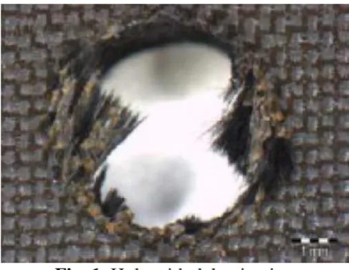
Machining of boreholes in carbon fiber-reinforced composites is much more difficult than in conventional materials. This difficulty is primarily represented by the structure of the material, consisting mainly of a matrix, reinforcing elements and auxiliary elements [1]. The mechanism of drilling composite materials has been studied by a large number of researchers, resulting the fact that the biggest problem for this type of materials machining is the appearance of delamination shown in figure 1 [2-4].
Fig. 1. Hole with delamination
Fig. 2. Peel-up delamination [5]
The push-down delamination occurs due to the axial force that the transverse edge of the bit exerts on the last layers of fiber at the exit of the hole. The more the drill bit approaches the end of the machining process, the uncut portion becomes thinner, thus decreasing its deformation resistance. At this point, there are cracks between the reinforcement layers and the matrix that propagate in the material over the hole diameter to a certain point, also called stop point, as can be seen in figure 3.
Fig. 3. Push-down delamination [5]
In order to minimize the delaminated area resulted after the drilling operation, a series of studies were made to determine the factors that led to the occurrence of this phenomenon. Hinze has demonstrated that the position of the laminate fibers relative to the position of the drill cutting edges in the drill exit area can lead to the delamination appearance [6].
Tsao and Hocheng, in a series of experimental researches, have shown that the axial force given by the feed rate plays an important role in the generation, propagation and magnitude of defects in the processing of fiber-reinforced composite materials [7-8]. They have developed an analytical model for calculating the maximum value of axial force that does not lead to defects. In this model, the critical axial force (FA) is related with properties
of the unidirectional laminate like the elastic modulus (E), the Poisson ratio (ν), the interlaminar fracture toughness (GIc) and the
uncut plate thickness (h).
3 18 ℎ
/
1 In a paper published in 2014, Ficici et al. have shown that regardless of the geometry and the material from which the cutting tool is produced, with the increase of the feed, the delamination factor also increases [9].
Marques, et al., demonstrated by practical tests that the spindle speed and, implicitly, the cutting speed have an essential role on delamination. In this case, there is a limit up to which the spindle speed can be increased. With its increase, the cutting speed also increases, resulting in higher temperatures in the processing area, thereby melting the material from which the matrix is produced [10].
Another factor that influences the occurrence of delamination is the drill point angle. At high-angle, the axial force components have an orientation approximately in the direction of the feed. According to Hummel, when drills with smaller point angle are used, the forces acting on the material are distributed approximately in radial directions so that the last layers of fiber are not pushed in the feed direction [11]. In addition, the use of small-angle angle drills makes the length of fibers that are cleaved from the array smaller.
The cutting edge radius of the drill it’s one of the most important geometrical parameter of the tool can lead to delamination appearance. At metallic materials drilling, it is necessary for the cutting edge to have a certain rounding. Besides the fact that the adhesion of the coatings is better as the rounding is higher, the edge stability is improved, thus increasing the durability of the cutting tool. Compared with the metallic materials, in CFRP drilling the cutting edge radius has a reversed effect. In this case, due to fibers small diameter when the cutting edge adius increase, the fibers are no longer cut, causing delamination to occur.
2. MATERIALS AND METHOD
2.1 Drilling equipment and materials
A Matsuura VX-1000 CNC machining centre (maximum power of 22 kW and maximum spindle speed of 15000 rpm) with an appropriate clamping system, was used to perform the drilling tests (fig 4.).
Fig. 4. Drilling set-up
The tests were conducted on M21/34% /UD194/IMA-12K, unidirectional carbon fiber laminate with the properties from table 1.
Table 1
Workpiece material properties [12]
As cutting tools, 9 WC-Co solid carbide step-drills, diameter Ø6,35 mm, with the geometry represented in figure 5, produced by Firma Gühring, were used.
Fig. 5. Drill geometry
2.2 Measurement of the delaminated area
In tests, the Keyence VHM 500 microscope was used to obtain the images and to evaluate the machined holes performed in the drilling process. The equipment has the necessary
functions to measure the magnitude of the delaminated area.
There are several methods to evaluate the delamination damage during drilling. Some of them are reported by Albuquerque et al. [13]. In the present study, the defects were evaluated using the delaminated area. The tests were stopped when the delamination area, measured with the Keyence equipment in the drill bit exit area, exceeds 1.6 mm2, this value representing
5% of the surface area of the machined hole. In figure 5, the first image is a Ø6,35 hole (radius r = 3,175) in which the delaminated surface is equal to 0, and in the second image is a hole in which the delaminated surface is equal to the surfaces a1+a2+a3, the test stop criterion being calculated with formula 2.
Fig. 5. A1- hole area; A2-delaminated area 5 ∙100 2
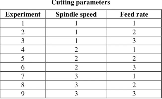
2.3 Taguchi experimental design approach The experimental design was made according to an L9 array based on Taguchi method with the feed rate and the spindle speed as control factors (Table 2).
Table 2
Cutting parameters
In this study, each parameter was designed to have three levels, with the values from Table 3.
Table 3
Cutting parameters / levels
Properties Units Value
Fiber Weave/DU Fiber Mass g/m² 194 Th. Calculated Cured Ply Thickness mm 0.184 Th. Calculated Fiber Volume % 59.2
Resin Density g/cm3 1.28
Fiber Desnsity g/cm3 1.78
Th. Calculated Laminate Density g/cm3 1.58
Tension Strength MPa 3050
Tension Modulus GPa 178
Compression Strength MPa 1500
Compression Modulus GPa 146
Experiment Spindle speed Feed rate
1 1 1
2 1 2
3 1 3
4 2 1
5 2 2
6 2 3
7 3 1
8 3 2
Taguchi method is using an appropriately chosen signal-to-noise ratio (S/N). The S/N ratios derived from quadratic loss function. Three of them, equations 3, 4 and 5, are considered to be standard.
Target crt. ∶ '
( 10 ∙ )*+ ,-.
/. 3 Minimizing crt. ∶(' 10 ∙ log 7∑ 97 4
Maximizing crt.: (' 10 ∙ log 7∑7,. 5 Where 9- is the average of the observed data, =2 is the variation of y, n is the number
of observations and y is the observed data. Regarding the results, the smaller S/N ratio corresponds to the best performance. In our case, the values of the S/N ratio taken into account will be those calculated according to the minimization criterion (formula 4), the objective being to determine the optimal cutting parameters combination for obtaining the smallest delaminated area.
3. RESULTS AND DISCUSSIONS
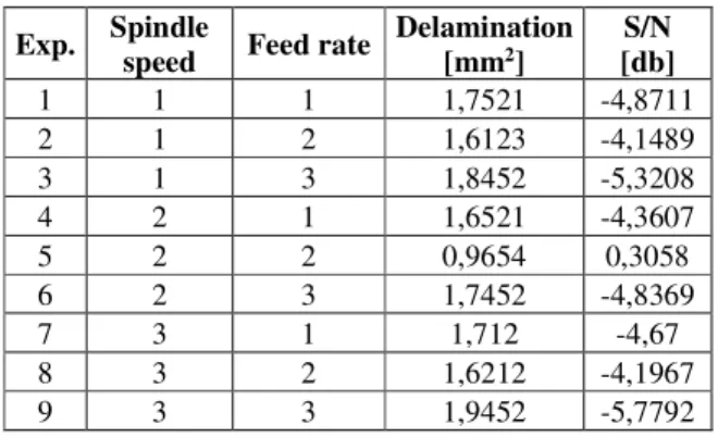
A drilling test was conducted to evaluate the effect of cutting parameters on the work-piece delamination. The delaminated area was measured using the Keyence VHX 5000 equipment. After measuring all the delaminated areas, the total delamination for each hole was calculated by summing the measured values. Table 4 shows the results obtained in measurements and values of the S/N ratio calculated with the help of Minitab software.
Table 4
S/N response table for delamination factor
From the above table, based on the results of the S/N ratio, the optimal cutting parameters for the delamination were obtained with feed rate at Level 2 (0,06 mm/U) and the spindle speed at Level 2 (5015 U/min), where S/N values have the smallest value.
Tables 5 and 6 show the effects values for response means. These, together with the mean response values of S/N reports for delamination areas, were calculated using the results of the experiments and the S/N ratios from Table 4.
Table 5
Response table for means
Table 6
Response table for S/N ratios
Where delta measures the effect magnitude taking into account the difference between the characteristic with the highest mean value and the characteristic with the lowest mean value for each factor. R (Rank) is a given value for identifying the factors that have the greatest effect on the results, the factor with the highest delta value receiving the value 1.
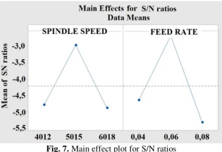
Figures 6 and 7 are the graphs for the response means values from Table 5 and the response average values for the S/N ratios from Table 6.
Fig. 6. Main effect plot for means Symbol parameter Cutting Level 1 Level 2 Level 3
A Spindle speed
n [U/min] 4012 5015 6018 B Feed rate
f [mm/U] 0,04 0,06 0,08
Exp. Spindle speed Feed rate Delamination [mm2] [db] S/N
1 1 1 1,7521 -4,8711
2 1 2 1,6123 -4,1489
3 1 3 1,8452 -5,3208
4 2 1 1,6521 -4,3607
5 2 2 0,9654 0,3058
6 2 3 1,7452 -4,8369
7 3 1 1,712 -4,67
8 3 2 1,6212 -4,1967
9 3 3 1,9452 -5,7792
Sym. Cutting param. Level 1 Level 2 Level 3 Delta R.
A Spindle
speed 1,737 1,454 1,759 0,305 2 B Feed
rate 1,705 1,400 1,845 0,446 1
Sym. Cutting param. Level 1 Level 2 Level 3 Delta R
A Spindle
speed -4,780 -2,964
-4,882 1,981 2 B Feed
rate -4,634 -2,680
Fig. 7. Main effect plot for S/N ratios
From these graphs, it can be observed that at spindle speed 5015 rev/min and feed rate 0,06 mm/U are obtained the best results. With higher values for spindle speed and feed rate the delaminated area increases due to the reason that also the thrust force that acts on the last fiber layers increases. With lower values, more heat is generated and transferred to the laminate in the drilling area as the time of drilling increases. This leads to the matrix softening, the result being an increase in the difficulty of fibers cutting.
The significance of the cutting parameters with respect to the delamination factor was investigated to determine more accurately the optimum cutting parameters combinations by using analysis of variance (ANOVA). In table 7, give the ANOVA results for drilling carbon fiber composite materials.
Table 7
ANOVA table for delamination surface
If the P value for a given factor is less than 0.05 means that the model term is significant. If a P value for a given factor is greater than 0.1 then the term is considered insignificant for the regression equation. In our case, both terms, spindle speed and feed rate, have values less than 0.1, the form of the regression equation for the mathematical model of the delaminated surface generated using the Minitab
software is:
> ?, A 1,487 C 0,011D C 0,07E 6 According to the formula (6) determined by the
Response Surface Method, the chart corresponding to the delamination surface was generated according to the used cutting parameters. The
graph generated in the Minitab software and represented in Figure 8 is called the Response Surface and allows observing the variation of the delamination surface generated by the two independent cutting parameters.
Fig. 8. Delamination response surface
4. CONCLUSIONS
The factor with the greatest influence on the delamination surface is represented by the feed rate, having the rank 1.
Percentage, by application of the response surface method, the surface of defects is generated 24.81% by the spindle speed and 67.24% by the feed rate, the difference of 7.95% being errors caused by external factors (machining errors, measurement, etc.).
Both the S/N ratio and the response surface, the best results were obtained by using spindle speed 5015 [U/min] and feed rate 0.06 [mm/U] feed rate.
5. REFERENCES
[1] Iancău H., Nemeș O., Materiale compozite. Concepţie şi fabricaţie, Ed. Mediamira, ISBN 973-9357-06-7, Cluj-Napoca, 2003. [2] Raghav K.S., Sankaraiah G., Rao H.R.,
Analysis of Delamination Parameters in Hybrid Composites Using Taguchi Method,
International Journal of Innovative Research in Science, Engineering and Technology, Vol. 5, Issue 8, pp. 15544-15551, ISSN 2347-6710, August 2016, India.
[3] Marques A.T., Magalhaes A.G., Durao L.M.P., Silva J.F., Delamination analysis of
carbon fibre reinforced laminates:
Evaluation of a special step drill, Composites Source Squares sum df squares Mean value F- value P- Contrition
A 0,09208 2 0,046041 6,24 0,059 24,81% B 0,24960 2 0,124802 16,92 0,011 67,24% Error 0,02950 4 0,007376 7,95%
Science and Technology, Vol. 69, pp. 2376-2382, 2009.
[4] Klocke F., Shirobokov A., Kerchnawe S., Wahl M., Mannens R, Feuerhack A, Mattfeld P., Experimental investigation of the hole accuracy, delamination, and cutting force in piercing of carbon fiber reinforced plastics,
1st Cirp Conference on Composite Materials Parts Manufacturing 66, pp. 215-220, 2017.
[5] Durao L.M.P., Tavares J.M.R., Albuquerque V.H.C, Marques J.F.S.,
Andrade O.N.G., Drilling Damage in Composite Material, Materials 2014, 7(5), pp. 3802-3819, Basel, 2014.
[6] Hinze W., Hartmann D., Goßmann U.,
Kantenqualität beim Umrissfräsen von CFK verbessern, VDI-Z 154, Nr.1/2, 2012. [7] Hocheng H., TsaoC.C., Comprehensive
analysis of delamination in drilling of composite materials with various drill bits, Journal of Materials Processing Technology 140, pp. 335–339, 2003.
[8] Hocheng H., TsaoC.C., Taguchi analysis of delamination associated with various drill bits in drilling of composite material,
International Journal of Machine Tools & Manufacture 44, pp. 1085–1090, 2004. [9] Ficici F., Ayparcasi Z., Effects of cutting
parameters on delamination during drilling
of Polyphthalamide (PPA) Matrix Composite
Material with 30% Glass Fiber
Reinforcement, Proceedings of the 4th International Congress APMAS2014, April 24-27, Fethiye, 2014.
[10] Marques A.T., Durao L.M., Magalhaes A.G., Tavares J.M., Delamination analysis of
carbon fibre reinforced laminates:
Evaluation of a special step drill, 16TH International conference on composite materials, Nr. 16, pp. 1-10, Kyoto, 2007.
[11] Müller-Hummel P., Bohren von
CFK/Titan-Stacks bei A350 Rumpf und
Flügel an Handarbeitsplätzen und
Nietautomaten in der Montage, presentation, 2011.
[12] Hexcel, „www.hexcel.com”, Available: http://www.hexcel.com/user_area/content_m edia/raw/HexPly_M21_global_DataSheet.pd f, 2017, [Accessed 10 August 2017].
[13] Albuquerque V.H.C., Durao L.M.P.,
Tavares J.M.R.S., Evaluation of
Delamination Damages on Composite Plates using Techniques of Image Processing and Analysis and a Backpropagation Artificial Neural Network, EngOpt 2008 - ICEO, Rio de Janeiro, Brazil, 01 - 05 June 2008.
STUDII EXPERIMENTALE PRIVIND INFLUENȚA PARAMETRILOR DE AȘCHIERE
ASUPRA DELAMINĂRII LA PRELUCRAREA CFRP UTILIZÂND METODA TAGUCHI
Rezumat: Găurirea materialelor compozite armate cu fibre de carbon (CFRP) este cea mai des întâlnită operație de prelucrare în timpul procesului de asamblare în industria aerospațialăși în industria auto. Datorită neomogenității CFRP, la burghierea acestor tipuri de materiale apar tipuri de defecte diferite comparativ cu burghierea materialelor tradiționale, cel mai critic fiind delaminarea. Scopul acestei lucrări este de a investiga influența avansului și a turației asupra delaminării rezultate în timpul burghierii de materialelor composite. Un plan de experimente bazat pe metoda Taguchi a fost realizat având în vedere o combinație a trei valori diferite pentru avansul și trei valori diferite pentru turația sculei așchietoare. Analiza varianței (ANOVA) a fost utilizată pentru a analiza rezultatele experimentului și pentru a determina parametrii optimi de așchiere.
Claudiu Ioan JUGRESTAN, DrD.Eng., Technical University of Cluj-Napoca, B-dul Muncii, no. 103-105, e-mail: [email protected], Phone +40748183996, Cluj-Napoca, Romania. Marcel Sabin POPA, Eng., Professor Dr., Technical University of Cluj-Napoca, B-dul Muncii, no.
103-105, e-mail: [email protected], Phone +40264401635, Cluj-Napoca, Romania. Stefan SATTEL, Eng., Gühring KG, Herderstraße 50-54 e-mail: [email protected], Cluj-
Albstadt, Germany.
Ovidiu Virgil VEREȘ, Eng., Technical University of Cluj-Napoca, B-dul Muncii, no. 103-105, e-mail: [email protected], Phone +40742645413, Cluj-Napoca, Romania.
![Fig. 2. Peel-up delamination [5]](https://thumb-us.123doks.com/thumbv2/123dok_us/7994948.2120066/2.918.108.419.104.278/fig-peel-up-delamination.webp)