©Science and Education Publishing DOI:10.12691/wmt-3-1-2
Design and Optimization of Coplanar Capacitive
Coupled Probe Fed MSA Using ANFIS
Gaurav Shete, Veerseh G. Kasabegoudar*
P. G. Department, MBES College of Engineering, Ambajogai, India *Corresponding author: [email protected]
Abstract
In this paper, an optimization method based on adaptive Neuro-Fuzzy inference system (ANFIS) for determining the parameters used in the design of a coplanar capacitive coupled probe fed rectangular microstrip antenna. The antenna was analyzed in the 2-10GHz range to demonstrate universal working of the proposed model. Here, an expert knowledge of fuzzy inference system (FIS) and the learning capability of artificial neural network (ANN) have been embedded (ANFIS). By calculating and optimizing the patch dimensions of a rectangular microstrip antenna with air gap, this paper shows that ANFIS produces good results that are in agreement with the mathematical analysis of the design parameters of antenna. Of the parameters considered for optimization, the error difference (average) between the proposed model and the calculated data is 0.21% for L, 0.41% for W, and 0.2% for air gap which are less than 0.5% and acceptably low.Keywords:
ANFIS, Patch W, Air gap g, Patch L, Wireless CommunicationCite This Article:
Gaurav Shete, and Veerseh G. Kasabegoudar, “Design and Optimization of Coplanar Capacitive Coupled Probe Fed MSA Using ANFIS.” Wireless and Mobile Technologies, vol. 3, no. 1 (2016): 7-12. doi: 10.12691/wmt-3-1-2.1. Introduction
Various wireless electronic systems are improved and also reduced into sizes and weights due to the development of modern integrated circuit technology. In many wireless communication systems, there is a requirement for low profile antennas as these antennas are less obstructive and in addition, snow, rain, or wind has less effect on their performance. Therefore, in many application, Microstrip antennas (MSAs) are used such as high performance aircraft, spacecraft, satellites, and missiles, where size, weight, cost, performance, ease of installation, and aerodynamic profile are constraints [1,2,3]. The radiating patch may be square, rectangular, circular, triangular, and any other configuration. In this paper, the rectangular microstrip patch antennas with small capacitive feed are considered [2]. To design microstrip patch antennas, analytical and numerical methods have been used, in the past. The analytical method, based on some fundamental simplifying physical assumptions regarding the radiation mechanism of antennas, which are the most useful for practical designs as well as for providing a good intuitive explanation of the operation of MSAs [2]. However, these methods are not suitable for many structures, in particular, if the thickness of the substrate is significant. The numerical methods are mathematically complex, and still cannot make a practical antenna design feasible within a reasonable period of time. They also, require strong background knowledge, and have time-consuming numerical calculations which need very expensive software packages.
Recently, many papers have reported various improved methods used in designing of microstrip patch antennas including the use of various forms of artificial intelligence [4-18]. However, none of these consider a capacitive feed in which probe is connected at a distance from the main radiating patch. Therefore, in this paper, a method based on the adaptive neuro-fuzzy inference system (ANFIS) is presented to effectively calculate and optimize the patch dimensions of a rectangular micro strip patch antenna with small capacitive feed. Also, many works that have been written on the same field have concentrated on optimizing only one feature (e.g. resonant frequency, patch length/width, or feed points etc.) in the design of MSA [1]. In this work we proposed a new artificial intelligence based method for calculating and optimizing the three important features in a design of an MSA; the patch length, patch width, and air gap (g). The final results are then validated with the mathematical analysis of the design parameters of antenna. Basic configuration of the antenna geometry considered for optimization is presented in Section 2. Section 3 briefly considers the architecture of adaptive neuro-fuzzy inference system. The proposed model is presented in Section 4. Results and discussions are included in Section 5. Finally, conclusions of the work carried out are included in Section 6.
2. Basic Configuration of MSA with
Capacitive Feed
bandwidth than the conventional rectangular MSA. The smaller dimension of capacitive feed improves the bandwidth as well as reduces the spurious radiations. Furthermore, this feed approach works well with conventional geometries such as rectangular and triangular patches and offers the impedance bandwidth close to 50% [2]. The ultra-wideband devices are those having a -10dB fractional bandwidth of at least 20 % in the range of 3.1-10.6 GHz. More details (theory, design, analysis, and comparisons) on this geometry can be found in [2,19].
Figure 1 shows the geometry of the suspended RMSA
with capacitive feed, where the larger patch works as the radiator and the smaller patch serves as a feed strip which couples the energy to the radiator by capacitive means [2]. In the basic configuration rectangular patch is used for both radiator and feed strip. The antenna substrate is placed above the ground plane at a height equal to air gap. The maximum bandwidth can be obtained with the help of this height. Detailed conventional design procedure and analysis for any frequency of interest for coplanar capacitively coupled probe fed UWB microstrip antenna can be found in [2].
Figure 1. Geometry of rectangular patch antenna with capacitive feed [2]
3. Architecture of Adaptive Neuro-Fuzzy
Interference System (ANFIS)
ANFIS network is organized into two parts like fuzzy systems. The first part is the antecedent and the second part is the conclusion, and the two are connected together by rules to form a network. The ANFIS architecture consists of five layers namely; fuzzy layer, product layer, normalized layer, de-fuzzy layer, and summation (total output) layer as shown in Figure 2. In the figure, a circle indicates a fixed node, whereas a square indicates an adaptive node. Assuming that the fuzzy inference system under consideration has two inputs x and y,and one output
z. Based on a first-order Sugeno model [3], a typical rule set with two fuzzy if-then rules can be expressed as;
Rule 1: If x is A1 and y is B1, then f1 = p1x + q1y + r1 (11) Rule 2: If x is A2 and y is B2, then f2 = p2x + q2y + r2 (12).
Where, A1, B1, A2 and B2 are fuzzy sets, pi, qi and ri
(i = 1, 2) are the coefficients of the first-order polynomial linear functions. More details on all five layers of ANFIS can be found in [3,8,9,14].
4. Application of ANFIS in the Design
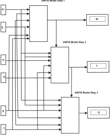
It is well known that ANFIS uses a set of data for training of its network. There are two types of data generators (measurements and simulations) for antenna applications. The selection of a data generator depends on the application and the availability of the data generator. In this work, the ANFIS model shown in Figure 3 with the inputs: substrate height (h), resonant frequency (fr), and
dielectric constant (εr), and the outputs: patch width (Wt),
patch length (Lt), and the feed point along the width and
length (Yf, Xf) respectively.
The ANFIS can simulate and analyze the mapping relation between the input and output data through a learning algorithm so as to optimize the parameters used in design of microstrip antennas. The training and test data sets used in this work have been obtained from both simulations and previous experimental works which are already reported in literature [2].
As shown in Figure 3, the ANFIS model used in this work is having four stages. In the first stage, resonant frequency, dielectric constant, and substrate height are used in optimizing the patch width (W) of the antenna. A total of 90 and 18 data sets were used for training and testing respectively. The membership functions (MFs) for the input variables fr, εr, and h are 4, 3, and 3, respectively.
The number of rules is then 36 (4x3x3) and the number of epochs is specified as 700. In the second stage, the antenna patch length (L) is optimized. The three input variables used in first stage are maintained with the addition of the optimized patch width (Wt) as an input variable, and therefore, variables fr, ε, r , h, and Wtwere
used as inputs with L as the output variable to be optimized. As stated earlier a total of 90 training data sets and 16 testing data sets were used in this stage.
The MFs for the input variables fr, ε r , h, and Wtare 4,
2, 2, and 4 respectively thus, the number of rules is 64 (4x2x2x4) with the number of iterations specified as 700. The third stage in the ANFIS model is used for optimizing the feed point (Yf) along the patch width. In this stage, the
number of epochs is specified as 600 with 90 testing data sets and 15 testing data sets used.
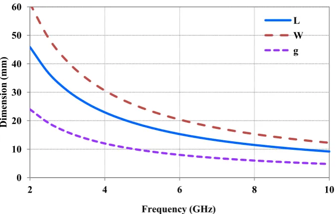
The variables fr, Wt, and Ltare used as inputs with the MFs as 3, 4, and 4, respectively. With 50 testing data sets, the number of iterations was specified as 500. As stated in earlier paragraphs, the input variables fr, Wt, and Ltwere allocated each with the MFs values as 3, 4, and 4 respectively, making the number of rules as 48 (3x4x4). The geometry parameters variations such as patch length (L), patch width (W), and airgap (g) versus frequency are indicated in Figure 4. As expected these parameters keep on decreasing with respect to increase in the frequency.
5. Results and Discussions
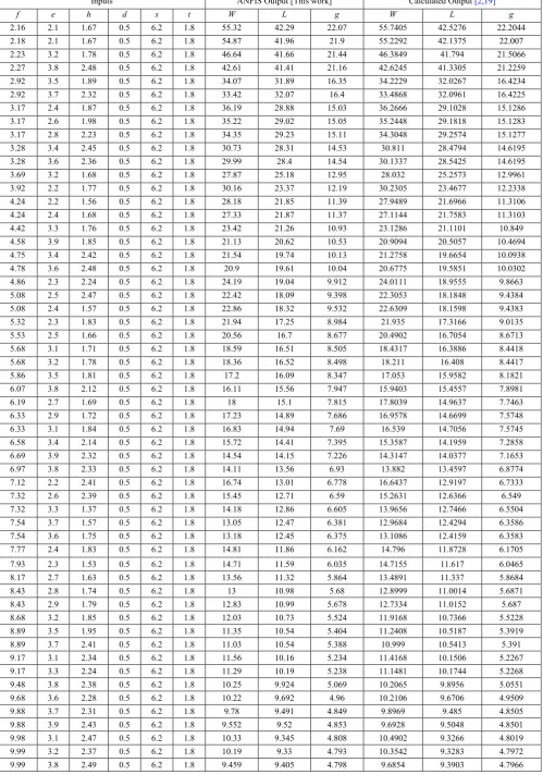
Training and testing of data sets was carried out by using ANFIS implemented in MATLAB platform. Also, the values of various MSA parameters namely patch width, patch length, and air gap are calculated by mathematical formulas. Finally, ANFIS optimized data were validated with previously reported works [2]. Table 1 shows a representative of the data sets obtained by using both ANFIS (MATLAB) and calculations. All data indicated in the table indicate that ANFIS calculates and optimizes the parameters effectively and agree with the calculated results. The error difference between the ANFIS and calculated results for the patch width is equal to 0.41% (average). Similarly, for patch length and airgap these values are 0.21%, and 0.2% which clearly demonstrate that overall error percentage is less than 0.5% and acceptably low and also demonstrates how effective ANFIS is in producing results close to calculated data.
6. Conclusions
This paper presented the procedure of optimization of parameters of coplanar capacitive coupled probe fed rectangular MSA with air gap. The average error difference between the ANFIS and calculated results for the patch width is found to be 0.41%. Similarly, for patch length and airgap these values are 0.21% and 0.2% respectively, and which clearly demonstrate that overall error percentage is less than 0.5% for all the cases considered. On comparing these data with calculated ones, it is clear that the ANFIS produces results which are in good agreement with the values reported in earlier works. As the traditional method of analyzing design parameter is complex and hence the optimization with ANFIS provides great simplified method for obtaining design parameters. Also, use of ANFIS in determining the design parameters are the fast and accurate than that of traditional methods.
Figure 4. Geometry parameters variations vs. frequency
0 10 20 30 40 50 60
2 4 6 8 10
Table 1. A representative of input variables, ANFIS output, and calculated output data
Inputs ANFIS Output [This work] Calculated Output [2,19]
f e h d s t W L g W L g
2.16 2.1 1.67 0.5 6.2 1.8 55.32 42.29 22.07 55.7405 42.5276 22.2044
2.18 2.1 1.67 0.5 6.2 1.8 54.87 41.96 21.9 55.2292 42.1375 22.007
2.23 3.2 1.78 0.5 6.2 1.8 46.64 41.66 21.44 46.3849 41.794 21.5066
2.27 3.8 2.48 0.5 6.2 1.8 42.61 41.41 21.16 42.6245 41.3305 21.2259
2.92 3.5 1.89 0.5 6.2 1.8 34.07 31.89 16.35 34.2229 32.0267 16.4234
2.92 3.7 2.32 0.5 6.2 1.8 33.42 32.07 16.4 33.4868 32.0961 16.4225
3.17 2.4 1.87 0.5 6.2 1.8 36.19 28.88 15.03 36.2666 29.1028 15.1286
3.17 2.6 1.98 0.5 6.2 1.8 35.22 29.02 15.05 35.2448 29.1818 15.1283
3.17 2.8 2.23 0.5 6.2 1.8 34.35 29.23 15.11 34.3048 29.2574 15.1277
3.28 3.4 2.45 0.5 6.2 1.8 30.73 28.31 14.53 30.811 28.4794 14.6195
3.28 3.6 2.36 0.5 6.2 1.8 29.99 28.4 14.54 30.1337 28.5425 14.6195
3.69 3.2 1.68 0.5 6.2 1.8 27.87 25.18 12.95 28.032 25.2573 12.9961
3.92 2.2 1.77 0.5 6.2 1.8 30.16 23.37 12.19 30.2305 23.4677 12.2338
4.24 2.2 1.56 0.5 6.2 1.8 28.18 21.85 11.39 27.9489 21.6966 11.3106
4.24 2.4 1.68 0.5 6.2 1.8 27.33 21.87 11.37 27.1144 21.7583 11.3103
4.42 3.3 1.76 0.5 6.2 1.8 23.42 21.26 10.93 23.1286 21.1101 10.849
4.58 3.9 1.85 0.5 6.2 1.8 21.13 20.62 10.53 20.9094 20.5057 10.4694
4.75 3.4 2.42 0.5 6.2 1.8 21.54 19.74 10.13 21.2758 19.6654 10.0938
4.78 3.6 2.48 0.5 6.2 1.8 20.9 19.61 10.04 20.6775 19.5851 10.0302
4.86 2.3 2.24 0.5 6.2 1.8 24.19 19.04 9.912 24.0111 18.9555 9.8663
5.08 2.5 2.47 0.5 6.2 1.8 22.42 18.09 9.398 22.3053 18.1848 9.4384
5.08 2.4 1.57 0.5 6.2 1.8 22.86 18.32 9.532 22.6309 18.1598 9.4383
5.32 2.3 1.83 0.5 6.2 1.8 21.94 17.25 8.984 21.935 17.3166 9.0135
5.53 2.5 1.66 0.5 6.2 1.8 20.56 16.7 8.677 20.4902 16.7054 8.6713
5.68 3.1 1.71 0.5 6.2 1.8 18.59 16.51 8.505 18.4317 16.3886 8.4418
5.68 3.2 1.78 0.5 6.2 1.8 18.36 16.52 8.498 18.211 16.408 8.4417
5.86 3.5 1.81 0.5 6.2 1.8 17.2 16.09 8.347 17.053 15.9582 8.1821
6.07 3.8 2.12 0.5 6.2 1.8 16.11 15.56 7.947 15.9403 15.4557 7.8981
6.19 2.7 1.69 0.5 6.2 1.8 18 15.1 7.815 17.8039 14.9637 7.7463
6.33 2.9 1.72 0.5 6.2 1.8 17.23 14.89 7.686 16.9578 14.6699 7.5748
6.33 3.1 1.84 0.5 6.2 1.8 16.83 14.94 7.69 16.539 14.7056 7.5745
6.58 3.4 2.14 0.5 6.2 1.8 15.72 14.41 7.395 15.3587 14.1959 7.2858
6.69 3.9 2.32 0.5 6.2 1.8 14.54 14.15 7.226 14.3147 14.0377 7.1653
6.97 3.8 2.33 0.5 6.2 1.8 14.11 13.56 6.93 13.882 13.4597 6.8774
7.12 2.2 2.41 0.5 6.2 1.8 16.74 13.01 6.778 16.6437 12.9197 6.7333
7.32 2.6 2.39 0.5 6.2 1.8 15.45 12.71 6.59 15.2631 12.6366 6.549
7.32 3.3 1.37 0.5 6.2 1.8 14.18 12.86 6.605 13.9656 12.7466 6.5504
7.54 3.7 1.57 0.5 6.2 1.8 13.05 12.47 6.381 12.9684 12.4294 6.3586
7.54 3.6 1.75 0.5 6.2 1.8 13.18 12.45 6.375 13.1086 12.4159 6.3583
7.77 2.4 1.83 0.5 6.2 1.8 14.81 11.86 6.162 14.796 11.8728 6.1705
7.93 2.3 1.53 0.5 6.2 1.8 14.71 11.59 6.035 14.7155 11.617 6.0465
8.17 2.7 1.63 0.5 6.2 1.8 13.56 11.32 5.864 13.4891 11.337 5.8684
8.43 2.8 1.74 0.5 6.2 1.8 13 10.98 5.68 12.8999 11.0014 5.6871
8.43 2.9 1.79 0.5 6.2 1.8 12.83 10.99 5.678 12.7334 11.0152 5.687
8.68 3.2 1.85 0.5 6.2 1.8 12.03 10.73 5.524 11.9168 10.7366 5.5228
8.89 3.5 1.95 0.5 6.2 1.8 11.35 10.54 5.404 11.2408 10.5187 5.3919
8.89 3.7 2.41 0.5 6.2 1.8 11.03 10.54 5.388 10.999 10.5413 5.391
9.17 3.1 2.34 0.5 6.2 1.8 11.56 10.16 5.234 11.4168 10.1506 5.2267
9.17 3.3 2.24 0.5 6.2 1.8 11.29 10.19 5.238 11.1481 10.1744 5.2268
9.48 3.8 2.38 0.5 6.2 1.8 10.25 9.924 5.069 10.2065 9.8956 5.0551
9.68 3.6 2.28 0.5 6.2 1.8 10.22 9.692 4.96 10.2106 9.6706 4.9509
9.88 3.7 2.31 0.5 6.2 1.8 9.78 9.491 4.849 9.8969 9.485 4.8505
9.88 3.9 2.43 0.5 6.2 1.8 9.552 9.52 4.853 9.6928 9.5048 4.8501
9.98 3.1 2.47 0.5 6.2 1.8 10.33 9.345 4.808 10.4902 9.3266 4.8019
9.99 3.2 2.37 0.5 6.2 1.8 10.19 9.33 4.793 10.3542 9.3283 4.7972
References
[1] K.V. Rop, D. B. Konditi, H.A. Ouma, and S.M. Musyoki,
“Parameter optimization in drsign of rectangular microstip patch
antenna using ANFIS technique,” International Journal on “Technical
and Physical Problems of Engineering, vol. 12, no. 3, Sep. 2012.
[2] V. G. Kasabegoudar, D. S. Upadhyay, and K. J. Vinoy, “Design
studies of ultra-wideband microstrip antennas with a small
capacitive feed,” International Journal of Antennas and
Propagation, vol. 2007, pp. 1-8, 2007.
[3] I. Singh et. al., “Microstrip patch antenna and its applications: a
survey,” Int. J. Comp. Tech. Appl., vol.2, pp. 1595-1599, 2011.
[4] K. Guney and N. Sirikaya, “Adaptive neuro-fuzzy inference
system for computing of the resonant frequency of circular microstrip
antennas,” ACES Journal, vol. 19, no. 3, pp. 188-197, 2004.
[5] N. Turker, F. Gunes, a n d T. Yildirim, “Artificial neural
design of microstrip antennas,” Turk J. Elec Engin, Tubitak, vol.
14, no. 3, pp. 445-453, 2006.
[6] C. A. Balanis, Antenna Theory-Analysis and Design, John Wiley
& Sons Inc., 2nd Ed ition , 1997.
[7] R.A. Saeed and K. Sabira, “Design of microstrip antenna for
WLAN,” Journal of Applied Sciences, vol. 5, no. 1, pp. 47-51, 2005.
[8] B. Milovanovic, M. Milijic, A. Atanaskovic, and Z. Stankovic,
“Modeling of patch antennas using neural networks,” Int. Conf. on
Telecommunications in Modern Satellite, Cable and Broadcasting Services (TELSIKS), pp. 386-388, 2005.
[9] K. Guney and N. Sarikaya, “Adaptive neuro-fuzzy inference
systems for computation of the bandwidth of electrically thin and
thick rectangular microstrip antennas,” Electrical Engineering
Journal, vol. 88, pp. 201-210, 2004.
[10] N.K. Kasabov, Foundations of Neural Networks, Fuzzy Systems,
and Knowledge Engineering, The MIT Press Cambridge,
Massachusetts London, England, 1996.
[11] J. S. R. Jang, “ANFIS: adaptive-network-based fuzzy inference
system,” IEEE Transactions on Systems, MAN, and Cybernetics,
vol. 23, no.3, pp. 665-685, 1993.
[12] S. N. Sivanandam, S. Sumathi, and S. N. Deepa, Introduction to
Fuzzy Logic Using MATLAB, Springer-Verlag Berlin Heidelberg, 2007.
[13] Z. I. Dafalla, W.T.Y. Kuan, A.M. Abdel Rahman, and S.C.
Shudakar, “Design of a rectangular microstrip patch antenna at
1GHz,” RF and Microwave Conference, Subang, Selangor,
Malaysia, pp. 145-149, 2004.
[14] A.B. Mutiara, R. Refianti, and Rachmansyah, “Design of
microstrip antenna for wireless communication at 2.4 GHz,”
Journal of Theoretical and Applied Information Technology, vol. 33 no.2, pp.184-192, 30th Nov., 2011.
[15] M. Aneesh, Jamshed A. Ansari, Ashish Singh, Kamakshi, and
Saiyed S. Sayeed, “Analysis of Microstrip line feed slot loaded
patch antenna using artificial neural network,” Progress in
Electromagnetic Research M, vol.58, pp. 35-46, 2014.
[16] V. V. Thakare and P. K. Singhal, “Bandwidth analysis by
introducing slots in microstrip antenna design using ANN,”
Progress in Electromagnetic Research M, vol. 9, pp. 107-122, 2009.
[17] L. H. Manh, F. Grimaccia, M. Mussetta, and R. E. Zich,
“Optimization of a dual ring antenna by means of artificial neural
network,” Progress in Electromagnetics Research B, vol. 58, pp.
59-69, 2014.
[18] J. S. Sivia, A. P. S. Pharwaha, and T. S. Kamal, “Analysis and
design of circular fractal antenna using artificial neural networks,”
Progress in Electromagnetics Research B, vol. 56, pp. 251-267, 2013.
[19] V.G. Kasabegoudar and K.J. Vinoy, “Coplanar capacitively
coupled probe fed microstrip antennas for wideband applications,”
![Figure 1. Geometry of rectangular patch antenna with capacitive feed [2]](https://thumb-us.123doks.com/thumbv2/123dok_us/1087786.2082859/2.595.101.500.200.771/figure-geometry-rectangular-patch-antenna-capacitive-feed.webp)