Concord Express Installation
Instructions
Copyright © 2012 UTC Fire & Security Americas Corporation, Inc.
Interlogix is part of UTC Climate Controls & Security, a unit of United Technologies Corporation. All rights reserved.
Trademarks and patents
Concord is trademarks of UTC Fire & Security.
Other trade names used in this document may be trademarks or registered trademarks of the manufacturers or vendors of the respective products.
Manufacturer UTC Fire & Security Americas Corporation, Inc. 1275 Red Fox Rd., Arden Hills, MN 55112-6943, USA
Contact information www.utcfireandsecurity.com or www.interlogix.com Customer support www.interlogix.com/customer-support
Notices
FCC Notices
FCC Part 15 Information to the User
Changes or modifications not expressly approved by UTC Fire & Security can void the user’s authority to operate the equipment.
FCC Part 15 Class B
This equipment has been tested and found to comply with the limits for a Class B digital device, pursuant to part 15 of the FCC Rules. These limits are designed to provide reasonable protection against interference in a residential installation. This equipment generates, uses, and can radiate radio frequency energy and, if not installed and used in accordance with the instructions, may cause harmful interference to radio communications. However, there is no guarantee that
interference will not occur in a particular installation.
If this equipment does cause harmful interference to radio or television reception, which can be determined by turning the equipment off and on, the user is encouraged to try to correct the interference by one or more of the following measures: • Reorient or relocate the receiving antenna.
• Increase the separation between the equipment and receiver.
• Connect the affected equipment and the panel receiver to separate outlets, on different branch circuits. • Consult the dealer or an experienced radio/TV technician for help.
ACTA Part 68
This equipment complies with Part 68 of the FCC Rules. Located on this equipment is a label that contains, among o ther information, the FCC registration number and the ringer equivalence number (REN) for this equipment. If requested, this information must be provided to the telephone company.
FCC Part 68 Registration No. B4ZUSA-27621-AL-E REN: 0.2B
The REN is used to determine the maximum number of devices that may be connected to your telephone line. Excessive RENs on a telephone line may result in devices not ringing in response to an incoming call. In most areas, the sum of all device RENs should not exceed five (5.0). To be certain of the number of devices that may be connected to a line, as determined by the total RENs, contact the local telephone company. For products approved after July 23, 2001, the REN for this product is part of the product identifier that has the format US:AAAEQ##TXXXX. The digits represented by ## are the REN without a decimal point (e.g., 03 is a REN of 0.3). For earlier products, the REN is separately shown on the label.
A plug and jack used to connect this equipment to the premises wiring and telephone network must comply with the applicable FCC Part 68 rules and requirements as adopted by ACTA. A compliant telephone cord and modular plug is provided with this product. It is designed to be connected to a compliant modular jack that is also compliant. See the Installation Instructions for details.
Alarm dialing equipment must be able to seize the telephone line and place a call in an emergency situation. It must be able to do this even if other equipment (telephone, answering system, computer modem, etc.) already has the telephone line in use. To do so, alarm dialing equipment must be connected to a properly installed RJ31X jack that is electrically in series and ahead of all other equipment attached to the same telephone line. Proper install ation is depicted in the following diagram. If you have any questions concerning these instructions, consult your local telephone company or a qualified installer about installing an RJ31X jack and alarm dialing equipment for you.
If this equipment causes harm to the telephone network, the telephone company may temporarily disconnect your service. If possible, you will be notified in advance. When advance notice is not practical, you will be notified as soon as possible. You will also be advised of your right to file a complaint with the FCC.
The telephone company may make changes in its facilities, equipment, operations, or procedures that could affect the operation of the equipment. You will be given advance notice in order to maintain uninterrupted service.
If you experience trouble with this equipment, please contact the company that installed the equipment for service and/or repair information. The telephone company may ask you to disconnect this equipment from the network until the problem has been corrected or you are sure that the equipment is not malfunctioning.
This equipment may not be used on coin service provided by the telephone company. Connection to party lines is subject to state tariffs
Patent Information
This product and the use of this product may be covered by one or more of the following patents: 5,805,063, 5,872,512, 5,942,981, 4,855,713. Except expressly provided herein, the purchase of this product shall not constitute a license or otherwise provide a right to practice a method covered by any of the identified patents. UTC Fire & Security hereby grants the purchaser of this product a limited, non-exclusive license to practice the methods patented in the identified patents solely with products manufactured, sold or licensed by UTC Fire & Security. This license grant does not extend to the use of unlicensed, third party products with this product.
Before installing this equipment, users should ensure that it is permissible to be connected to the facilities of the local telecommunications company. The equipment must also be installed using an acceptable method of connection. In some cases, the company’s inside wiring associated with a single-line individual service may be extended by means of a certified connector assembly (telephone extension cord). The customer should be aware that compliance with the above conditions may not prevent degradation of service in some situations.
Repairs to certified equipment should be made by an authorized Canadian maintenance facility designated by the supplier. Any repairs or alterations made by the user to this equipment, or equipment malfunctions, may give the telecommunications company cause to request the user to disconnect the equipment.
For your protection, make sure that the electrical ground connections of the power utility, telephone lines, and internal metallic water pipe system, if present, are connected together
Caution: Do not attempt to make connections yourself. Contact the appropriate electrician or electric inspections
authority.
The Load Number (LN) assigned to each terminal device denotes the percentage of the total load to be connected to a telephone loop which is used by the device, to prevent overloading. The termination on a loop may consist of any combination of devices subject only to the requirement that the total of the LNs of all the devices does not exceed 100. Load Number: .1 The term “IC:” before the certification/registration number only signifies that the Industry Canada technical specifications were met. IC: 867A 787SIMON
“AVIS: - L ´
étiquette du ministère des Communications du Canada identifie le matériel homologué. Cette étiquette certifie que le matériel est conforme a certaines normes de protection, d ´ exploitat ion et de sécurité des réseaux de
télécommunications. Le ministère n ´ assure toutefois pas que le matériel fonctionnera a la satisfaction de l ´ utilisateur. Avant d ´ installer ce matériel, l ´ utilisateur doit s ´ assurer qu´ il est permis de le raccorder aux installations de l ´ enterprise locale de télécommunication. Le matériel doit également etre installé en suivant une méthod acceptée de raccordement. Dans certains cas, les fils intérieurs de l´ enterprise utilisés pour un service individuel a ligne unique peuvent etre prolongés au moyen d´ un dispositif homologué de raccordement (cordon prolongateur téléphonique interne). L ´ abonné ne doit pas oublier qu ´ il est possible que la conformité aux conditions énoncées ci -dessus n ´ empechent pas le dégradation du service dans certaines situations. Actuellement, les enterprises de télécommunication ne permettent pas que l ´ on raccorde leur matériel a des jacks d ´ abonné, sauf dans les cas précis prévus pas les tarrifs particuliers de ces enterprises.
Les réparations de matériel homologué doivent etre effectuées pas un centre d ´ entretien canadien autorisé désigné par le fournisseur. La compagne de télécommunications peut demander a l ´ utilisateur de débrancher un appareil a la suite de réparations ou de modifications effectuées par l ´ utilisateur ou a cause de mauvais fonctionnement.
Pour sa propre protection, l ´ utilisateur doit s ´ assurer que tous les fils de mise a la terre de la source d ´ énergie électrique, des lignes téléphoniques et des canalisations d ´´ eau métalliques, s ´ il y en a, sont raccordés ensemble. Cette précaution est particulièrement importante dans les régions rurales.
Avertissment. - L ´ utilisateur ne doit pas tenter de faire ces raccordements lui-meme; il doit avoir recours a un service d ´ inspection des installations électriques, ou a electricien, selon le cas”.
Une note explicative sur les indices de charge (voir 1.6) et leur emploi, a l ´ intention des utilisateurs du matériel termin al, doit etre incluse dans l ´ information qui accompagne le materiel homologué. La note pourrait etre rédigée selon le modèle suivant:
“L ´ indice de charge (IC) assigné a chaque dispositif terminal indique, pour éviter toute surcharge, le pourcentage de la charge totale qui peut etre raccordée a un circuit téléphonique bouclé utilisé par ce dispositif. La terminaison du circuit bouclé peut etre constituée de n ´ import somme des indices de charge de l ´ ensemble des dispositifs ne dépasse pas 100.”
Content
Notices
Chapter 1
Installation 1
Special installation requirements 2
Planning the Installation 6
Installing the System 7
Chapter 2
Programming 27
Entering programming mode 28
Programming Tier 1 Menu Items 30
Programming Tier 2 Menu Items 32
Chapter 3
Testing/Troubleshooting 71
Troubleshooting 76
Appendix A
System configuration worksheets 85
Appendix B
Programming mode menus and settings 103
Chapter 1
Installation
This manual provides information for planning, installing, programming, and
testing this security system. When necessary, this manual refers you to other
documentation included with compatible devices.
Planning sheets are included for you to record hardware layout and software
programming settings.
Content
Special installation requirements 2
UL Listed Systems 2
UL-Canada Listed Systems 5
Planning the Installation 6
Standard Panel 6
Touchpads 6
SnapCard™ 7
Installing the System 7
Determine the Panel Location 8
Total System Power and Wire Length Guidelines 8
Mounting the Panel 10
Identify Panel Components 11
Connecting the Panel to Earth Ground 12
Installing Optional SnapCards 13
Installing Optional Hardwire Input Modules (HIMs) 13
Connecting Detection Devices to Panel Zone Inputs#14
Chapter 1
2 Concord Express Installation Instructions
Special installation requirements
This security system can be used as a wire warning system, an intrusion alarm
system, an emergency notification system, or any combination of the three.
Some installations may require configurations dictated by city or state codes,
insurance, or Underwriter’s Laboratories (UL). This section describes the various
component and configuration listings.
UL Listed Systems
This section describes the requirements for UL Listed systems.
Basic System
• Control Panel (60-806, 60-806-95R)
• Backup Battery, 12 VDC, 4 AH (60-681)
• SuperBus 2000 2x16 LCD Touchpad (60-746-01), SuperBus 2000 Fixed
Display Touchpad (60-820), SuperBus 2000 2x20 LCD Touchpad (60-803), or
SuperBus 2000 2x20 VFD Touchpad (60-804)
• Standard Class II 16.5 VAC, 25 VA Power Transformer; manufacturer—Tech
Electro Ind, Inc. Part No. 48A0164 (60-822) or Standard Class II 16.5 VAC,
40 VA Power Transformer; MG Electronics Model # MGT1640CC, UTC Fire &
Security # 22-156
• 15-Watt, Dual Tone Siren (13-469) or Hardwire Siren (13-046)
Household Burglary Alarm System Unit (UL 1023)
Basic system, plus:
• Hardwire Magnetic Contact (Sentrol part # 1075-N or 1038T-N) or Wireless
Learn Mode Door/Window Sensor (60-362), Wireless Learn Mode PIR Motion
Sensor (60-703-95, 60-511, or 60-639)
• IMMEDIATE TROUBLE BEEPS set to on
• UL 98 OPTIONS set to on
• RECEIVER FAILURE set to on
• EXIT DELAY set to 60 seconds or less
• QUICK EXIT set to off
• SIREN TIMEOUT set to 4 minutes or more
• SIREN VERIFY set to on
Chapter 1
• RF TX TIMEOUT set to 24 hours
• EXTENDED DELAY set to off
• TWO TRIP ERROR set to off
• ALARM VERIFY set to off
• DISABLE TROUBLE BEEPS set to off
• SYSTEM TAMPER set to on
Household Fire Warning System (UL 985)
Basic system plus:
• Hardwire Smoke Detector:
System Sensor models 2100D, 2100TD, 2100S, 2100TS, 2400, or 2400TH
learned into Sensor Group 26 Sentrol (ESL) models 429AT, 521B, or 521BXT
learned into sensor group 26
• Wireless Smoke Sensor 60-506-319.5 or 60-645-95 learned into sensor
group 26
• IMMEDIATE TROUBLE BEEPS set to on
• UL 98 OPTIONS set to on
• RECEIVER FAILURE set to on
• SIREN VERIFY set to on
• RF TX TIMEOUT set to 4 hours
• ALARM VERIFY set to off
• DISABLE TROUBLE BEEPS set to off
UL 1023 & 985 24-Hour Backup
For 24-hour backup, the total current draw for all connected devices is limited to
90 mA continuous using a 4.0 AH battery.
SIA System Requirements
Note
: UL requirements take priority over SIA requirements.
Chapter 1
4 Concord Express Installation Instructions
Shortcut # Function Programmin g page reference Default setting Required setting 0003 SIA False Alarm Reduction 34 On On 0013 Exit Extension 35 On On 0014 Auto Stay Arming 35 On On 0016 Duress Code 36 Disabled Disabled 02005 Dialer Abort 43 On On 02006 Dialer Abort Delay 43 30 Sec. 15-45 sec. 02007 Cancel Message 43 On On 02009 Call Wait Cancel
44 Disabled On if reporting to central station and customer has call waiting
0310 Entry Delay 46 30 sec. 30-240 sec. 0311 Exit Delay 47 60 sec. 45-184 sec. 05014 Swinger
Limit
52 1 1
0900 Smoke Verify
61 Off On if smoke alarms are programmed into system
N/A Cross Zoning
88 Disabled Enabled for zones with a high probability of false alarms
The following table describes non-programmable (hard coded) system operation
as required to meet ANSI-SIA CP-01 and is provided only for your reference.
Function Operation
Disarm During Entry Delay Enter Code Only (or 1 + CODE) Cancel Alarm Enter Code Only (or 1 + CODE) Abort Annunciation Enabled
Cancel Report Annunciation Enabled
UL 1635 Digital Alarm Communicator System
Note
: For UL 1635 installations, Entry Delay plus Dialer Abort Delay must not
exceed 60 seconds.
Chapter 1
• AC FAILURE set to on
• PHONE NUMBER must be programmed
• HIGH LEVEL REPORTS set to on.
• LOW LEVEL REPORTS set to on
• PHONE TEST set to on
• AUTO PHONE TEST set to on
• PHONE TEST FREQ. set to 1
• NEXT PHONE TEST set to 1
• LOW CPU BATTERY set to on
• COMM FAILURE set to on
• RF TX TIMEOUT set to 4 hours
Central Station Reporting
The panel has been tested with the following central station receivers using SIA
and Contact ID reporting formats:
• CS-5000 Central Station Receiver
• Sur-Gard Central Station Receiver with models SG-DRL2A and SG-CPM2
UL-Canada Listed Systems
This section describes the requirements for ULC (UL Canada) Listed systems.
• CSA Certified Accessories
The UL-Canada Basic System is nearly the same as the “UL Basic System”
described previously, the only difference being that you must use the ITI
60-679-CN Class II transformer (Basler part number BE 116250-AAA) to power
the panel.
• Residential Burglary Alarm System Unit
(CAN/ULC-S309)
Same as “UL Basic System and Household Burglary Alarm System Unit (UL
1023)” described previously and siren timeout must be set to 5 minutes or
more.
Residential Fire Warning System Control Unit (CAN/ULC-S545-M89)
Same as “UL Basic System and Household Fire Warning System (UL 985)”
described previously.
Chapter 1
6 Concord Express Installation Instructions
• SMOKE VERIFY must be set to off
Planning the Installation
This section describes the system capabilities to help you get familiar with the
system. To help you prepare for system installation, Appendix A provides
planning sheets with tables that let you record the hardware and programming
configuration of the system.
Standard Panel
The following describes the basic panel (out-of-box) hardware capabilities.
•
Power:
Input for an AC step-down, plug-in style transformer.
•
Auxiliary Power Output
: Output that supplies up to 750 mA (90 mA for UL
Listed systems) at 12 VDC for bus devices and hardwired detectors, such as
touchpads and motion detectors.
•
Bus A and B
: Input and output that provide communication between bus
devices and the panel.
•
2 Onboard Outputs
: One 12-volt and one open-collector output that can be
set up to activate other signalling devices, based on system events.
•
6 Supervised Hardwire Zones
: Factory programmed inputs for various
hardwired detectors (see “Accessory Modules Menu” on page 60 for a list of
factory programmed settings). Zone 6 can be set up in programming to
accept 2-wire smoke detectors.
•
Built-In Radio Receiver:
Allows use of UTC Fire & Security 319.5 MHz.
crystal and/or SAW Learn Mode wireless sensors and touchpads.
•
Phone Line Connection:
Allows the panel to communicate with central
monitoring stations and pagers.
Touchpads
The following describes the different touchpads that can be used for system
programming and operation.
•
SuperBus 2000 2x16 LCD Alphanumeric Touchpad
: Provides complete
system programming and operation control. Displays system messages, and
indicates system status.
Chapter 1
• S
uperBus 2000 2x20 LCD/VFD Alphanumeric Touchpads
: Provide
complete system programming and operation control, display system
messages and indicate system status.
•
SuperBus 2000 Fixed Display LCD Touchpad:
Provides operation control
and user programming access (
not installer or dealer programming
). Displays
system messages and indicates system status.
SnapCard™
The following SnapCards expand the system as described:
•
8Z Input SnapCard:
Provides eight additional hardwire zone inputs, of which
two are dedicated for 2-wire smoke detectors.
•
4 Output SnapCard
: Provides four form C relay outputs that can be set up to
activate other signalling devices, based on system events.
•
4Z Input/2 Output Combo SnapCard:
Provides three standard hardwire
zone inputs, one 2-wire smoke detector loop input, and two outputs that can
be set up to activate other signalling devices that are based on system
events.
Installing the System
This section describes how to install the system control panel. Before starting the
installation, plan your system layout and programming using the worksheets
provided in Appendix A.
Installing the system consists of the following steps:
• Determining the Panel Location
• Identifying Total System Power and Wire Length Guidelines
• Mounting the Panel
• Identifying Panel Main Components
• Installing Optional SnapCards
• Installing Optional HIMs
Chapter 1
8 Concord Express Installation Instructions
Determine the Panel Location
Before permanently mounting the panel, determine the location using the
following guidelines:
• To help reduce wire run lengths and labor, centrally locate the panel with
relation to detection devices whenever possible.
• Avoid running wires parallel with electrical wiring or fixtures, such as
fluorescent lighting, to prevent wire runs from picking up electrical noise.
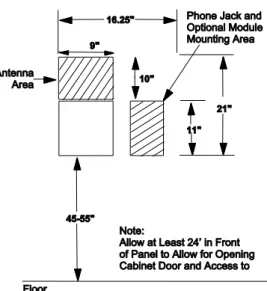
• Mount the panel at a comfortable working height (about 45 to 55 inches from
the floor to the bottom of the panel, as shown in Figure 1 below).
• Leave space to the left and right of the panel for wiring, phone jack, and
optional modules.
• For installations that include wireless sensors, allow at least 10 inches above
the panel cabinet for the antenna.
• Allow at least 24 inches in front of the panel for opening the panel door.
Figure 1: Determining panel locationTotal System Power and Wire Length Guidelines
Note
: A) Class 2, Class 3, and power-limited fire alarm circuits must be installed
using FPL, FPLR, FPLP, or substitute cable permitted by the National Electrical
Code ANSI/NFPA 70. Wire that extends beyond the cable jacket must be
separated from all other conductors by a minimum of 1/4-inch or by a
nonconductive barrier.
Chapter 1
(B) Class 2, Class 3, and power-limited fire alarm circuit conductors must be
installed as Class 1 or higher circuits.
Table 1 below describes panel voltage/current output ranges. See Appendix A for
maximum and standby device current draw.
Table 1: Panel voltage/surrent output ranges Panel terminal Voltage range Max. current
4 (+12V) 8.5 - 14.2 VDC 9.1 - 14.2 VDC (UL)
750 mA—non-UL Listed systems 90 mA—UL Listed systems
7 (OUT1/+12) 8.5 - 14.2 VDC 1.25 A at default configuration—non-UL Listed systems 650 mA—UL Listed systems
17 (Z6/2W+) 8.9 - 13.7 VDC 80 mA
Total system wire allowed varies depending on devices powered by the panel,
wire length between devices and the panel, and the combined wire length of all
devices.
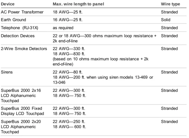
Table 2 below describes the maximum wire length allowed between compatible
devices and the panel.
Table 2: Maximum device wire lengths
Device Max. wire length to panel Wire type
AC Power Transformer 18 AWG—25 ft. Stranded
Earth Ground 16 AWG—25 ft. Solid
Telephone (RJ-31X) as required Stranded
Detection Devices 22 or 18 AWG—300 ohms maximum loop resistance + 2k end-of-line
Stranded 2-Wire Smoke Detectors 22 AWG—330 ft.
18 AWG—830 ft.
(based on 10 ohms maximum loop resistance + 2k end-of-line)
Stranded
Sirens 22 AWG—80 ft.
18 AWG—200 ft. when using siren models 13-469 or 13-046 Stranded SuperBus 2000 2x16 LCD Alphanumeric 22 AWG—300 ft. 18 AWG— 750 ft. Stranded
Chapter 1
10 Concord Express Installation Instructions
Device Max. wire length to panel Wire type
SuperBus 2000 2x20 VFD Alphanumeric Touchpad 22 AWG—250 ft. 18 AWG— 600 ft. Stranded SuperBus 2000 Hardwire Input Module 22 AWG—1,800 ft. 18 AWG— 4,500 ft. Stranded
Mounting the Panel
Use the following procedure to mount the panel to the wall or wall studs.
Caution:
Make sure you are free of static electricity whenever you work on the
panel with the cover open. To discharge any static, first touch the metal panel
chassis, then stay in contact with the chassis when touching the circuit board.
Using an approved grounding strap is recommended.
To mount the panel cabinet and circuit board:
1. Open the panel door and slide it up to remove it from the cabinet. Set the
door aside.
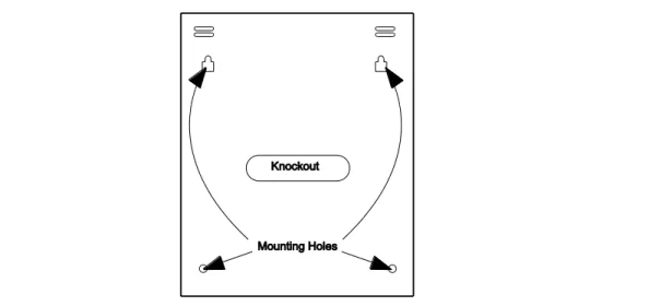
2. Remove the knockout to provide access for system wiring (see Figure 2
below).
3. Feed all device wires through the knockout and place the panel in position
against the wall.
4. Level the panel and mark the top and bottom mounting holes (see Figure 2
below).
Chapter 1
5. Install anchors where studs are not present.
6. Partially insert screws into the two top mounting hole locations, then hang the
panel on the two screws.
7. Recheck for levelness, insert the two lower screws, and tighten all four
mounting screws.
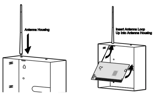
8. Install the antenna housing (included with the panel) by pushing it down into
the top left hole of the cabinet until it snaps into place (see Figure 3 below).
9. Install the circuit board into the cabinet, inserting the loop antenna loop up
into the antenna housing (see Figure 3 below), then secure the circuit board
with the four mounting screws (included).
Figure 3: Installing the antenna housing and the circuit board
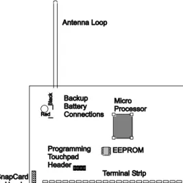
Identify Panel Components
Before installing devices and making wiring connections, familiarize yourself with
the main components of the panel. Figure 4 on page 12 shows the main
Chapter 1
12 Concord Express Installation Instructions
Figure 4: Main component locations
Connecting the Panel to Earth Ground
For maximum protection from lightning strikes and transients, connect the
lower-right circuit board screw to earth ground as shown in Figure 5 below. Use
16-gauge, solid copper wire from an earth grounded cold water pipe clamp to the
panel.
Note
: For best results, it is recommended that you crimp a spade lug on the wire
end at the panel and secure the lug under the circuit board screw as shown in
Figure 5 below.
Chapter 1
Installing Optional SnapCards
The SnapCard Header on the lower-left side of the panel accepts one of the
following SnapCard models:
• 8Z Input SnapCard—60-757
• 4 Output SnapCard—60-758
• 4Z Input/2 Output Combo SnapCard—60-756
Install the desired SnapCard onto the panel SnapCard Header and secure it in
place with two screws, included with the card (Figure 6 below).
Connect all necessary input/output wiring using the
installation instructions
included with the SnapCard.
Figure 6: Installing a SnapCardInstalling Optional Hardwire Input Modules (HIMs)
Each SuperBus 2000 8-Zone Input Module (60-774) adds eight supervised
hardwire zones to the system. Both normally open and normally closed detectors
can be wired to module inputs (see Figure 8 on page 15).
Connect all necessary input/output wiring using the
installation instructions
Chapter 1
14 Concord Express Installation Instructions
Figure 7: Installing and connecting the HIM in the Concord Express
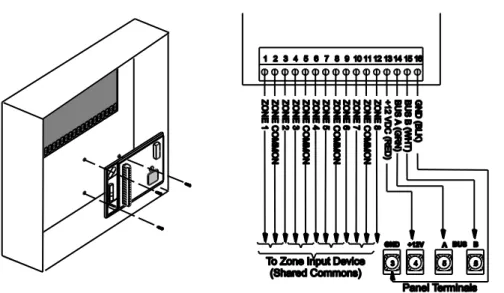
Connecting Detection Devices to Panel Zone Inputs
The panel comes with six factory programmed onboard hardwire zones (see
“Accessory Modules Menu” on page 60 for factory settings). Zone inputs 1
through 6 are supervised using a 2k-ohm, end-of-line resistor (included with
panel) at the last device on the circuit.
Note
: Install an end-of-line resistor on all unused, factory programmed, onboard
panel zones.
All six zones accept either normally open (N/O) or normally closed (N/C)
detection devices (see Figure 8 on page 15).
The maximum loop resistance for each zone input is 300 ohms, plus the 2k
end-of-line (EOL) resistor.
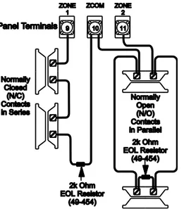
Connecting Intrusion Detection Devices
Figure 8 on page 15 shows the typical wiring for N/C and N/O door/window
intrusion detection.
Chapter 1
Figure 8: Connecting N/C and N/O intrusion detection circuits
Figure 9 below shows the typical wiring for Optex model RX-040 (PI) PIR motion
detectors. The minimum available panel voltage for hardwired PIR motion
detectors is 8.5 VDC (9.1 VDC for UL Listed systems).
Figure 9: Connecting a PIR motion detectorConnecting 2-Wire Smoke Detectors
Chapter 1
16 Concord Express Installation Instructions
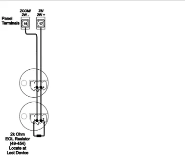
Note
: When using 2-wire smoke detectors on Zone 6, the Two-Wire Smoke
setting (in program mode) must be turned on before entering the LEARN
SENSORS menu. See ONBOARD OPTIONS—INPUTS in the section “Entering
programming mode” on page 28 for complete details.
WARNING:
Use only 2-wire smoke detector models described above. Alarm
signals from other detectors may not be processed correctly if the panel has lost
AC power and is operating only from the backup battery.
When set up for 2-wire smoke detectors, zone 6 can handle up to 10 smoke
detectors with 120
µ
A maximum idle current per detector. Maximum total loop
current allowed in an alarm condition is 80 mA. The maximum loop resistance for
2-wire smoke detectors connected to zone input 6 is 10 ohms, plus the 2k
end-of-line resistor.
Caution:
Panel terminal 16 (ZCOM/2W-) cannot be used as a common
loopconnection for any other zones, when using Zone 6 for 2-wire smoke
detectors.
Connect one or more 2-wire smoke detectors to the panel as shown in Figure 10
below.
Figure 10: Connecting 2-wire smoke detectors
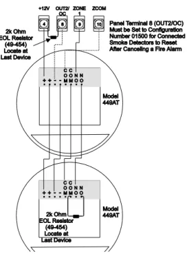
Connecting 4-Wire Smoke Detectors
Zone inputs 1 through 6 can be used with 4-wire smoke detectors that latch and
remain in the alarm state until power is removed and then restored to the
Chapter 1
The panel provides this power interruption from panel terminal 8 (OUT2/OC)
provided that the output configuration number is set (in program mode) to 01500.
For more information on output configuration numbers, see the section
“Programming the Panel” and the tables in Appendix A. Use only 4-wire smoke
detectors that operate on 8.5 to 14.2 VDC.
Note
: The Two-Wire Smoke setting (in program mode) must be off when
connecting
4-wire smoke detectors to zone 6. For UL Listed systems, 4-wire smoke
detectors cannot be connected to onboard panel zone inputs.
Connect up to five Sentrol (ESL) model 449AT (ITI part no. 13-360) smoke
detectors to panel power input as shown in Figure 11 below.
Figure 11: Connecting 4-wire smoke detectors
Connecting Sirens
Chapter 1
18 Concord Express Installation Instructions
Note
: If the backup battery is not connected, or if the configuration of panel
terminal 7 is programmed to anything other than the default (00410), then the
combined currents of terminal 7 (OUT 1/+12) and terminal 4 (+12V) must not
exceed 750 mA.
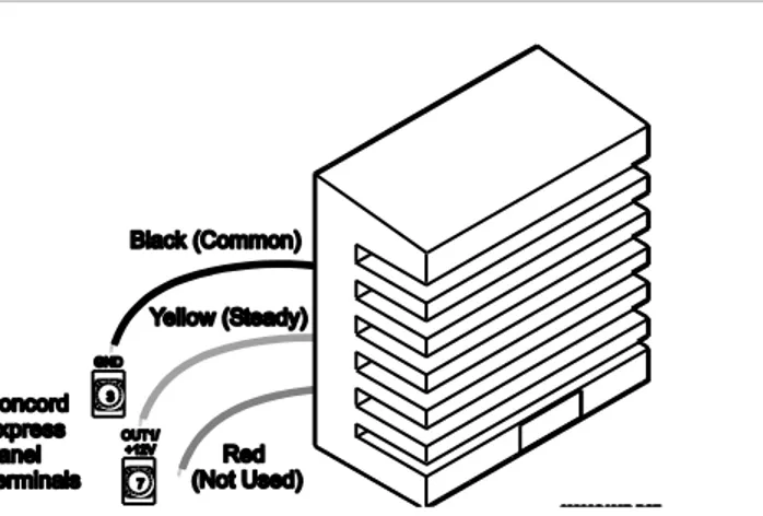
15-Watt, Dual Tone Siren (13-469)
Panel terminal 7 (OUT1/+12V) is a +12V programmable output. At the default
configuration setting (00410), this output can provide up to 1.25 A during an
alarm (650 mA for UL Listed systems) if the backup battery is connected.
The default configuration setting (00410) activates the output during any audible
alarm, allowing for a siren connection without changing the output configuration
number.
Note
: For UL Listed systems, Siren Verify must be on.
Figure 12: Connecting 15-watt, Dual-Tone siren 13-469
Note
: Some versions of this siren may have two wires of each color. Only one
black wire and one yellow wire are needed for panel connections.
For UL Listed installations, you can connect only one 15-Watt, Dual-Tone Siren
to panel terminals 3 and 7 as shown in Figure 12 above. For all other
installations, connect up to two sirens. This siren does not require an end-of-line
resistor.
Hardwire Siren (13-046)
Connect one or two sirens to the panel with supervision as shown in Figure 13 on
page 19. If Siren Verify is turned off, the 2k end-of-line resistor is not required.
Note
: For UL Listed systems, Siren Verify must be on and the 2k end-of-line
Chapter 1
Figure 13: Connecting hardwire siren 13-046
Interior Piezo Siren (30-006)
Panel terminal 8 (OUT2/OC) is an open-collector (switched path-to-ground),
programmable output that can handle up to a 200 mA current.
The default setting (01710) activates the output for status and alarm tones, which
allows for a piezo siren connection without changing the output configuration
number.
Connect the piezo siren to the panel terminals with a 2k end-of-line resistor as
shown in Figure 14 below.
Note
: Piezo siren connections to terminal 8 require a 2k end-of-line
resistor that
can be located at the panel since it does not supervise the circuit.
Figure 14: Connecting an interior piezo sirenNote
: If using an external power supply instead of panel terminal 4, the supply
voltage must be limited to 9.5 VDC maximum and the negative side of the power
supply must be connected to panel ground (terminal 3).
Chapter 1
20 Concord Express Installation Instructions
Panel terminal 7 (OUT1/+12V) is a +12-volt programmable output. At the default
configuration setting (00410), this output can provide up to 1.25 A during an
alarm (650 mA for
UL Listed systems) if the backup battery is connected.
Note
: If the backup battery is not connected, or if the configuration of panel
terminal 7 is programmed to anything other than the default (00410), then the
combined currents of terminal 7 (OUT 1/+12) and terminal 4 (+12V) must not
exceed 750 mA.
The default configuration setting (00410) activates the output during any audible
alarm.
The following siren drivers, self-contained sirens, and bells have been tested and
found compatible for use with the panel:
• Moose Models MPI-11 (use only 8-ohm speaker loads), MP-47, MP-47B
• Altronix Model ALSD2 (4- or 8-ohm speaker loads)
• ATW Models DT-24, DS508 (both self-contained)
• Wheelock MB-G6-12 Six-inch, 12V Bell
Refer to the manufacturer’s documentation for installation details.
Connecting Touchpads
• SuperBus 2000 2x16 LCD Alphanumeric Touchpad (60-746-01)
• SuperBus 2000 2x20 LCD Alphanumeric Touchpads (60-803, 60-809)
• SuperBus 2000 2x20 VFD Alphanumeric Touchpad (60-804, 60-810)
• SuperBus 2000 Fixed Display LCD Touchpad (60-820)
Alphanumeric touchpads can be used for installer programming, system
operation, and user programming. Fixed display touchpads can be used for
system operation and user programming but not for installer programming.
Note
: Be sure to have an alphanumeric (programming) touchpad on hand for
on-site programming in installations that do not include one as part of the final
system configuration. This programming touchpad can be connected to the
Programming Touchpad Header (see Figure 15 on page 21) using a
Programming Touchpad Cable (part no. 60-791).
Connect 2x16 and fixed display LCD touchpads to the panel power output and
bus terminals as shown in Figure 15 on page 21.
The 2x20 LCD/VFD touchpads include a supervised hardwire input for
connection to a hardwire detection device (see Figure 15 on page 21 for an
example of a normally closed connection).
Chapter 1
Connect 2x20 LCD/VFD touchpads to the panel power output and bus terminals
as shown in Figure 15 below.
Figure 15: Connecting 2x16 Alphanumeric Fixed Display LCD touchpad and 2x20 LCD/VFW touchpads
Installing an RJ-31X Phone Jack (13-081)
Note
: The panel cannot be used on a digital or PBX phone line. These systems
are designed only for digital type devices that operate anywhere from 5 volts DC
and up. The panel uses an analog modem and does not have a digital converter,
adapter, or interface to operate with such systems.
Use the following guidelines when installing an RJ-31X phone jack for system
control by phone and central station monitoring.
• Locate the RJ-31X jack (CA-38A in Canada) no further than five feet from the
panel.
• The panel must be connected to a standard analog (loop-start) phone line.
• For full line seizure, install an RJ-31X phone jack on the premises phone line
so the panel is ahead of all phones and other devices on the line. This allows
the panel to take control of the phone line when an alarm occurs even if the
phone is in use or off-hook.
Chapter 1
22 Concord Express Installation Instructions
To connect a phone line to the panel using an RJ-31X/CA-38A jack:
1. Run a 4-conductor cable from the TELCO protector block to the jack location
(see A in Figure 16 below).
2. Connect one end of the cable to the jack (see B in Figure 16 below).
Figure 16: Installing an RJ-31X Phone Jack3. At the TELCO protector block, remove the premises phone lines (lines from
phone jacks on premises) from the block and splice them to the black and
white (or yellow) wires of the
4-conductor cable (see C in Figure 16 above).
Note
: Connecting the panel to an analog line off the phone switch places the
panel ahead of the phone system which prevents panel access from phones
on the premises. However, the panel can still be accessed from off-site
phones.
4. Connect the green and red wires from the 4-conductor cable to the TIP (+)
and RING (-) posts on the block (see D in Figure 16 above).
5. Check the phones on the premises for dial tone and the ability to dial out and
make phone calls. If phones do not work correctly, check all wiring and make
corrections where necessary. Proceed to the “Troubleshooting” section of this
manual if problems persist.
Connecting the Phone Line to the Panel with a DB-8
Cord
After installing the RJ-31X jack, you are ready to connect the phone line to the
panel. A DB-8 cord (not included) uses a plug at one end for connecting to the
RJ-31X module and flying leads on the other end for panel terminal connections.
Chapter 1
To connect the DB-8 cord to the panel terminals and RJ-31X jack:
1. Connect the green, brown, gray, and red flying leads from the DB-8 cord to
panel terminals 18, 19, 20, and 21 (see Figure 17 below).
2. Insert the DB-8 cord plug into the RJ-31X (see Figure 17 below).
Figure 17: Connecting the DB8 cord3. Check the phones on the premises for dial tone and the ability to dial out and
make phone calls. If phones do not work correctly, check all wiring and
correct where necessary. Proceed to the “Troubleshooting” on page 76 of this
manual if problems persist.
Connecting the AC Power Transformer
Note
: If you plan on connecting an alphanumeric touchpad to the programming
touchpad header on the panel, do not connect it until after the panel is powered
up. Refer to “Entering Programming Mode.”
The panel must be powered by a plug-in stepdown transformer that supplies 16.5
VAC, 25 VA (60-822 or 60-679-CN). Connect the power transformer to the panel
as shown in Figure 18 on page 24.
Caution:
Do not plug in the power transformer at this time. The panel must be
powered up using the sequence of steps described in “Powering Up the Panel”
on page 24.
Chapter 1
24 Concord Express Installation Instructions
Figure 18: Connecting the power transformer
Powering Up the Panel
Note
: Without AC power, shutdown will occur if battery voltage falls below 10.2
VDC.
After installing SnapCards and wiring all devices to the panel, you are ready to
apply AC and backup battery power to the panel.
To power up the panel:
1. Connect the red and black battery leads (included with panel) to the lugs
located in the upper-left area of the panel circuit board (see Figure 19 below).
Figure 19: Connecting the backup battery2. Connect the battery leads to the battery terminals as shown.
3. Plug the transformer into an outlet that is not controlled by a switch or ground
fault circuit interrupt (GFCI).
Chapter 1
Alphanumeric touchpads display ************, SCANNING BUS DEVICES,
then a date and time display. Fixed display touchpads briefly show all text, no
text, BUS SCAN, then a time display.
4. To permanently mount the transformer, unplug it and remove the existing
screw securing the AC outlet cover.
5. Hold the outlet cover in place and plug the transformer into the lower
receptacle.
6. Use the screw supplied with the transformer to secure the transformer to the
outlet cover.
WARNING:
Use extreme caustion when securing the transformer to a metal
outlet cover. You could receive a serious shock if a metal outlet cover drops onto
the prongs of the plug while you are securing the transformer and cover to the
outlet box.
Note:
If touchpads don’t display anything, immediately unplug the transformer
Chapter 2
Programming
This section describes how to program all settings found in programming mode.
For on-site system programming, an alphanumeric touchpad is required.
Content
Entering programming mode 28
Touchpad Button Programming Functions 29
Moving Through Program Mode Tiers and Menus 29
Programming Tier 1 Menu Items 30
Programming Tier 2 Menu Items 32
Using Shortcut Numbers 32
Exiting Programming Mode 64
Entering User Programming Mode 64
Downloader Programming 69
Chapter 2
28 Concord Express Installation Instructions
Entering programming mode
Enter programming mode on site from an alphanumeric touchpad using an
installer/dealer code (default = 4321). The system can be put into program mode
only when it is disarmed.
To enter programming mode using an alphanumeric touchpad connected
to the panel terminals:
1. Make sure the system is disarmed.
2. Press 8 + CODE + 0 + 0. The touchpad shows SYSTEM PROGRAMMING.
Note
: If the programming touchpad is connected before the panel is powered
up, it will be added (learned) into panel memory as a permanent touchpad.
To enter programming mode using a programming touchpad:
1. Connect the red, black, green, and white wires from the Programming
Touchpad Cable (60-791) to the power and bus wires on an alphanumeric
touchpad while matching the wire colors on each.
2. Make sure the system is powered up and disarmed.
3. Connect the plug on the cable onto the panel programming touchpad header
(see Figure 20 below).
Figure 20: Connecting a programming touchpad
4. Press 8 + 4321 + 0 + 2. The touchpad sounds one short beep and the display
shows a flashing star. Press * and the display shows SERVICE TOUCHPAD
ACTIVE.
Chapter 2
6. After programming is completed, simply disconnect the touchpad from the
panel header.
Touchpad Button Programming Functions
In program mode, the touchpad buttons let you navigate to all installer
programming menus for configuring the system. Table 3 below describes the
touchpad button functions in program mode.
Table 3: Alphanumeric touchpad buttons
Button Programming function
# Selects menu item or data entry.
* Deselects menu item or data entry (if pressed before #).
A & B Scroll through available options at the current menu tier. Also scroll through sensor text options during sensor text programming.
C Enters pauses when programming phone numbers. D Deletes certain programmed settings.
0 thru 9 Enter numeric values wherever needed. 1 & 2 Select off (1) or on (2) wherever needed.
1 thru 6 Press and hold to enter alphabetical characters A thru F for account numbers. 7 or 9 Press and hold to enter * (7) or # (9) for phone numbers.
Moving Through Program Mode Tiers and Menus
There are two basic tiers of programming menus. Tier 1 menus are accessible
immediately after entering program mode (see Figure 21 below).
Chapter 2
30 Concord Express Installation Instructions
The arrow below the SYSTEM PROGRAMMING menu represents pressing # to
move to tier 2 programming menus.
Only when SYSTEM PROGRAMMING is displayed can you advance to tier 2
menus (see Figure 22 below).
Figure 22: Tier 2 programming menus
Again, arrows pointing right represent pressing B, arrows pointing left represent
pressing A.
Arrows below each menu represent pressing # (or Ç) to advance to (or back up
from) those settings that pertain to that menu. Only when a specific menu is
displayed can you advance to those settings. For example, pressing # from the
SENSORS
menu gives you access to learning sensors, programming sensor text,
deleting sensors, and viewing sensor programming.
Settings in tier 2 menus can also be accessed by entering shortcut numbers. See
the section, “Programming Tier 2 Menu Items” on page 32 for complete details.
Programming Tier 1 Menu Items
This section guides you through programming tier 1 menu items as they appear
in sequence. The exact order you need to follow will depend on whether you’re
installing a new system or changing the programming of an existing system.
Chapter 2
Demo Kit Mode System Programming
(Default = Off)
This setting determines whether the panel is used for a standard installation (off) or as a demo kit (on). Turning on this feature and performing a memory clear changes the following settings: • System Master Code = 1234
• User Code 00 = 1001 (standard user code capabilities)
• User Code 01 = 1002 (standard user code capabilities, bypass sensors)
• User Code 04 = 1122 (standard user code capabilities, system tests)
• Zone 1 (hardwire) = Group 10, Front Door • Zone 2 (hardwire) = Group 13, Bedroom Window • Zone 3 (hardwire) = Group 17, Living Room PIR • Zone 4 (hardwire) = Group 01, Panic
• Zone 5 (wireless) = Group 01, Keychain Touchpad • Zone 6 (wireless) = Group 13, Kitchen Window • COMM FAILURE = off
• Entry Delay = 8 seconds • Exit Delay = 8 seconds • Extended Delay = 1 minute • Siren Timeout = 2 minutes • Status Beeps = on (all touchpads)
• Central Station Reporting = sensors learned into groups 01 and 03, Duress code use, and phone test (8 + CODE + 2)
To turn Demo Kit Mode On or Off:
1. With the display showing DEMO KIT OFF/ON (current setting), press 1 (off) or 2 (on). The display flashes the entered setting.
2. Press # and the display shows DEMO KIT OFF/ON (new setting). 3. Clear panel memory to
enable the demo kit mode (see next menu).
Clear Memory (System Programming) System Programming
Clearing memory with the Dealer Code deletes all existing programming except the Dealer Code. If the Dealer Code HAS NOT been set, clearing the memory with the Installer Code deletes all existing programming.
If the Dealer Code HAS been set, clearing the memory with the Installer Code deletes all existing
To clear Panel Memory:
1. With the system in program mode, press B until the display shows CLEAR MEMORY.
2. Press # and the display shows ENTER CODE TO CLEAR MEMORY.
Chapter 2
32 Concord Express Installation Instructions
Programming Tier 2 Menu Items
This section guides you through programming tier 2 menu items as they appear
in sequence. Each menu on tier 2 represents a group of settings related to the
menu name. Refer to Figure 22 on page 30 for the menus available on tier 2.
Using Shortcut Numbers
To go directly to a setting in tier 2, you can enter the shortcut number for that
setting. Shortcut numbers in this manual appear in parenthesis ( ), next to the
setting name. For example this heading shows the Downloader Code shortcut to
be 0000.
Downloader code (0000) System Programming
Shortcut numbers can be used from any setting location within tier 2.
To advance to tier 2 program menus:
With the system in program mode and the display showing SYSTEM
PROGRAMMING, press # once. The display should show SECURITY.
Security Menu
The SECURITY menu lets you choose whether security settings affect the whole
system (global) or a specific partition.
Important:
Each security access code (Installer, Dealer, System Master, or
User) must be unique. Do not us the same combination of numbers for any two
codes.
To access global or partition security menu items:
1. With the display showing SECURITY, press #. The display should show
GLOBAL.
2. Press # again to advance to global settings
OR
Press A or B to display PARTITION 1, then press # to advance to partition 1
settings.
The following describes how to program the security settings that appear under
GLOBAL.
Chapter 2
Downloader Code (0000) Security-Global (Default = 12345)
The 5-digit downloader code is used in conjunction with downloader programming. The down-loader operator must have the panel account number and downloader code in order to perform any
programming.
Note: The Downloader Code cannot be deleted from panel memory. To change the Downloader Code to its default setting, enter 12345 in the procedure to the right. The Downloader Code will be reset to defaults during a Memory Clear only if the Dealer Code is not set OR if the Dealer Code is used to initiate the Memory Clear.
To program a Downloader Code:
1. With the display showing DOWNLOADER CODE nnnnn (current code), enter the desired 5-digit code, + #. The display flashes the entered code.
2. Press # and the display shows DOWNLOADER CODE nnnnn (new code).
Installer Code (0001) Security-Global (Default = 4321)
The 4-digit installer code is used for entering program mode and changing system settings. If a dealer code is programmed, only those settings not associated with phone numbers can be changed.
Note: The Installer Code cannot be deleted or cleared from panel memory. To change the Installer Code to its default setting, enter 4321 in the procedure above.
To program an Installer Code:
1. With the display showing INSTALLER CODE nnnn (current code), enter the desired 4-digit code + #. The display flashes the entered code.
2. Press # and display shows
INSTALLER CODE nnnn (new code).
Dealer Code (0002) Security-Global (Default = none)
The 4-digit dealer code is used to prevent unauthorized persons from changing the programmed central station phone numbers and the Downloader Access Code. When this feature is enabled, central station phone numbers and the Downloader Code cannot be changed (unless you enter the program mode by using the dealer code). All other system settings are still accessible by entering the program mode with the installer code.
To program a Dealer Code:
1. With the display showing DEALER CODE ****,
enter the desired 4-digit code. The display flashes the entered setting.
2. Press # and the display shows the new code.
To delete a Dealer Code:
With the display showing DEALER CODE nnnn
(current code), press D. The display shows
DEALER CODE ****.
Note: The Dealer Code cannot be deleted by clearing panel memory.
Chapter 2
34 Concord Express Installation Instructions
SIA False Alarm Reduction (0003) Security-Global (Default = on)
Controls the following settings that are required by the SIA False Alarm Reduction Standard: • Arming level changes made from wireless
touchpads and keychain touchpads are sounded (beeps) on exterior siren output (on) OR are not sounded on exterior siren output (off).
Note: The siren output must be configured for “Exterior Siren” (016xx) for the arming level beeps to be annunciated.
• The Arming Always Silent feature is disabled for users if this setting is on OR can be controlled by users if the setting is off. Silent Arming on Demand is not affected.
To turn SIA False Alarm Reduction off or on:
1. With the display showing SIA FALSE ALARM
(current setting), press 1 (off) or 2 (on). The display flashes the entered setting.
2. Press # and the display shows the new setting.
The following describes how to program the security settings that appear under
PARTITION 1.
Account Number (0010) Security-Partition 1 (Default = 00000)
The account number is used as panel (or customer) identification for the central monitoring station. The panel sends the account number every time it reports to the central station. Account numbers must be 1 to 10 characters long.
Alpha characters A-F can be assigned to the account number by pressing and holding buttons 1-6 respectively until the character appears.
To program an Account Number:
1. With the display showing ACCOUNT NUMBER nnnnn (current number), enter the desired
account number. The display flashes the entered setting.
2. Press # and the display shows the new number.
Quick Arm (0011) Security-Partition 1 (Default = off)
Quick Arm allows system arming without using an access code. When this feature is on, the system arming level can be increased from Level OFF to LEVEL 2-STAY, from Level 1-OFF to LEVEL 3-AWAY, or from Level 2-STAY to LEVEL 3-AWAY without entering an access code. A valid access code is still required to decrease the arming level or disarm the system.
To turn Quick Arm off or on:
1. With the display showing QUICK ARM OFF/ON (current setting), press 1 (off) or 2
(on). The display flashes the entered setting.
2. Press # and the display shows the new setting.
Chapter 2
Quick Exit (0012) Security-Partition 1 (Default =
on)
This setting determines whether or not users can open and close a standard entry or exit door without causing an alarm (while the system is armed). This feature would be useful if the user wanted to go out to get the morning paper while the system was armed. This feature also allows the user to leave the armed premises without having to disarm and rearm the system.
Note: For UL Listed systems, Quick Exit must be turned off. When this feature is on, pressing D on a touchpad (while the system is armed) starts a 2-minute timer that allows one standard entry or exit door (sensor groups 10 and 19 only) to be activated once (opened, then closed).When this feature is turned off, the system must be disarmed before opening any protected door.
To turn Quick Exit off or on:
1. With the display showing
QUICK EXIT OFF/ON (current
setting), press 1 (off) or 2 (on). The display flashes the entered setting.
2. Press # and the display shows the new setting.
Exit Extension (0013) Security-Partition 1 (Default =
on)
This setting determines whether or not the system automatically arms to STAY (level 2) if the user arms the system to AWAY (level 3) without exiting the premises. This can help prevent accidental alarms by deactivating interior motion sensors during occupied arming periods.
Note: Arming the system to AWAY with No Delay overrides the Auto Stay Arming feature.
With the feature turned on, the user arms the system to AWAY. Touchpads (and other status sounders) emit one exit delay beep every four seconds, then one every second during the last 10 seconds. If the exit delay time expires with no standard delay sensor activation, the system automatically arms to STAY.
To turn Auto Stay Arming off or on:
1. With the display showing
AUTO STAY ARMING OFF/ON
(current setting), press 1 (off) or 2 (on). The display flashes the entered setting.
2. Press # and the display shows the new setting.
Chapter 2
36 Concord Express Installation Instructions
Auto Stay Arming (0014) Security-Partition 1 (Default =
on)
This setting determines whether or not the system automatically arms to STAY (level 2) if the user arms the system to AWAY (level 3) without exiting the premises. This can help prevent accidental alarms by deactivating interior motion sensors during occupied arming periods.
Note: Arming the system to AWAY with No Delay overrides the Auto Stay Arming feature.
With the feature turned on, the user arms the system to AWAY. Touchpads (and other status sounders) emit one exit delay beep every four seconds, then one every second during the last 10 seconds. If the exit delay time expires with no standard delay sensor activation, the system automatically arms to STAY.
To turn Auto Stay Arming off or on:
1. With the display showing
AUTO STAY ARMING OFF/ON
(current setting), press 1 (off) or 2 (on). The display flashes the entered setting.
2. Press # and the display shows the new setting.
Keyswitch Sensor (0015) Security-Partition 1 (Default =
none)
This feature lets users arm and disarm the system using either a keyswitch wired to a hardwire zone input or a wireless door or window sensor.
For example, if sensor 1 is designated as the keyswitch sensor and the system is disarmed, then tripping sensor 1 arms the system to AWAY. If the system is armed to STAY or AWAY, tripping sensor 1 disarms the system. The panel reports opening, closing, and force armed reports (if these features are turned on) to the central monitoring station. Note: A bypassed keyswitch sensor cannot arm or disarm the system.
During an audible alarm, keyswitch sensors can disarm the system (which sends a cancel report to the central
monitoring station), but cannot arm the system. The system can be armed only after siren timeout expires.
Keyswitch sensors test the same as any other sensor and do not arm or disarm the system during a sensor test.
To assign a Keyswitch Sensor:
1. With the display showing
KEYSWITCH SENSOR n (current
sensor number), enter the desired sensor number (01-24). The display flashes the entered sensor number.
2. Press # and the display shows the new number.
Chapter 2
Duress code (0016) Security-Partition 1 (Default = none)
The duress code is a unique 4-digit access code that allows users to operate the system and, at the same time, instructs the panel to send a silent alarm report to the central station.
Do not use a duress code unless it is absolutely necessary. Using duress codes often results in false alarms due to code entry errors. If a duress code is absolutely necessary, use it with an Interrogator® audio verification module (AVM) to reduce false alarms and accidental dispatches.
Note: To use this feature, the Duress Option setting under the REPORTING—PARTITION 1 menu must be turned on.
To program a Duress Code:
1. With the display showing DURESS CODE ****, enter the desired 4-digit
duress code. The display flashes the entered setting.
2. Press # and the display shows the new code.
To delete a Duress Code:
With the display showing DURESS CODE nnnn (current code), press D. The
display shows DURESS CODE ****.
Phones Menu
The PHONES menu lets you set up central station reporting for the system
(global) and pager reports (partition specific). The following describes how to
program the settings that appear under CS PHONE 1-2.
Phone Number (0100-cs phone 1, 0110-cs phone 2)
Phones-CS Phone 1-2 (Default = none)
(Default = none) This setting is used for programming the central station receiver phone number. Phone numbers can be 1-24 digits long, including pauses or * and # characters. To enter pauses, press C. To enter *, press and hold 7 for one second. To enter #, press and hold 9 for one second.
Note: The PHONE NUMBER menus are not accessible if a Dealer Code is
programmed and the Installer Code is used to enter installer programming mode. To access these menus when a Dealer Code is programmed, you must enter installer programming mode using the Dealer Code. A phone number must be programmed for UL 1635 listed installations.
To program a Central Station Phone Number:
1. With the display showing PHONE NUMBER _ (or
current number), enter the desired phone number. The display flashes the entered number.
2. Press # and the display shows the new number. Note: Call-waiting services should be disabled to prevent interruptions to panel communication to the central monitoring station (or pager). To program a dialing prefix that disables call-waiting, see the Call Wait Cancel setting under the menu PHONE OPTIONS—GLOBAL.
To delete a Central Station Phone Number:
With the display showing PHONE NUMBER n (current
number), press D. The display shows PHONE NUMBER _.
Chapter 2
38 Concord Express Installation Instructions
High Level Rpts (0101-cs phone 1, 0111-cs phone 2)
Phones-CS Phone 1-2 (Default: CS Phone 1=on, CS Phone 2=off)
When this setting is on, the panel reports to the central station events that involve a high-level security risk, including the following conditions: • Fire, Police, Auxiliary, Duress, and Freeze
alarms • No Activity
• Receiver Failure (or jam)
• System Tamper (40 incorrect keystrokes or touchpad supervisory),
• Entering or exiting Sensor Test mode
Note: For UL 1635 listed installations, this feature must be set to on for the programmed phone number.
To turn High-Level Reports off or on:
1. With the display showing HIGH LEVEL RPTS OFF/ON (current setting), press 1
(off) or 2 (on). The display flashes the entered setting.
2. Press # and the display shows the new setting.
Low Level Rpts (0102-cs phone 1, 0112-cs phone 2)
Phones-CS Phone 1-2 (Default: CS Phone 1=on, CS Phone 2=off)
When this setting is on, the panel reports non-alarm conditions to the central station, including the following conditions:
• Force Armed
• Hardwire Zone Trouble (open or short) • Supervisory (wireless devices)
• Low Battery (wireless devices) • Other non-alarm related conditions
Note: For UL 1635 listed installations, this feature must be set to on for the programmed phone number.
To turn Low-Level Reports off or on:
1. With the display showing LOW LEVEL RPTS OFF/ON (current setting), press 1
(off) or 2 (on). The display flashes the entered setting.
2. Press # and the display shows the new setting.
Open/Close Rpts (0103-cs phone 1, 0113-cs phone 2)
Phones-CS Phone 1-2 (Default=off)
When this setting is on, the panel sends a report when the system is armed (closed) or disarmed (opened).
Note: To use this feature, the Opening Reports and Closing Reports settings under the REPORTING menu must be turned on.
To turn Opening/Closing Reports off or on:
1. With the display showing OPEN/CLOSE RPTS OFF/ON (current setting), press 1 (off) or 2 (on).
The display flashes the entered setting.
![User s Manual. LG Programmable Logic Controller KGL for Windows [ MASTER-K Series] LG Industrial Systems Co., Ltd.](data:image/gif;base64,R0lGODlhAQABAIAAAP///wAAACH5BAEAAAAALAAAAAABAAEAAAICRAEAOw==)