NO COPYING WITHOUT BSI PERMISSION EXCEPT AS PERMITTED BY COPYRIGHT LAW
BSI Standards Publication
Technical product
documentation and
specification
Publishing and copyright information
The BSI copyright notice displayed in this document indicates when the document was last issued.
© BSI 2011
ISBN 978 0 580 72757 3 ICS 01.110; 01.100.01
The following BSI references relate to the work on this standard: Committee reference TDW/4/8
Draft for comment 11/30234091DC
Publication history
Originally published as BS 308-1, BS 308-2 and BS 308-3 First published as BS 8888 August 2000
Second edition, October 2002 Third edition, October 2004 Fourth edition, October 2006 Fifth edition, October 2008
Sixth (present) edition, December 2011
Amendments issued since publication
Date Text affected
Contents
Foreword iv
1 Scope 1
2 Normative references 1
3 Terms and definitions 1
4 Standards underpinning BS 8888 2
Section 1: Technical product documentation 4
5 Types of documentation 4
6 Drawing sheets 4
7 Title block 7
8 Scales 10
9 General tolerances 10
10 Conventions for arrangement of views on a TPD 12
11 Mechanical engineering drawings 15
12 Diagram 17
13 Lines, arrows and terminators 18
14 Lettering 18
15 Projections 19
16 Views 19
17 Sections 20
18 Symbols and abbreviations 20
19 Representation of features 22
20 Representation of components 22
Section 2: Technical product specification 25
21 Fundamental principles 25
22 Dimensioning and tolerancing 27
23 Rules for parenthetic statements 32
24 Features 32
25 Datums and datum systems 33
26 Rules for datums and datum systems 44
27 Geometrical tolerances 53
28 Surface texture indication 66
29 Graphical representation and annotation of 3-D data (3-D modelling output) 67
30 Verification 67
31 Security 68
32 Storage and retrieval 68
33 Marking 69
34 Protection notices 70
Annexes
Annex A (normative) Normative references 71
Annex B (informative) Bibliography 77
Annex C (normative) Geometrical tolerancing 79
Annex D (normative) Document security – Enhanced 85
Annex E (informative) Technical product specification – Geometrical product specification (GPS) 86
List of figures
Figure 1 – Size A4 to A0 5
Figure 2 – Title block in compact form 9
Figure 3 – Title block with person name fields on additional line 9
Figure 4 – Examples of general tolerance notes 12
Figure 5 – Labelled view method 13
Figure 6 – First angle projection method 14
Figure 7 – First angle projection method – Graphical symbol 14
Figure 8 – Third angle projection method 15
Figure 9 – Third angle projection method – Graphical symbol 15
Figure 10 – Section in one plane 16
Figure 11 – Section in two parallel planes 16
Figure 12 – Section in three contiguous planes 17
Figure 13 – Auxiliary view showing true shape of inclined surface 20
Figure 14 – Permissible interpretations when no form control is given on the drawing 28
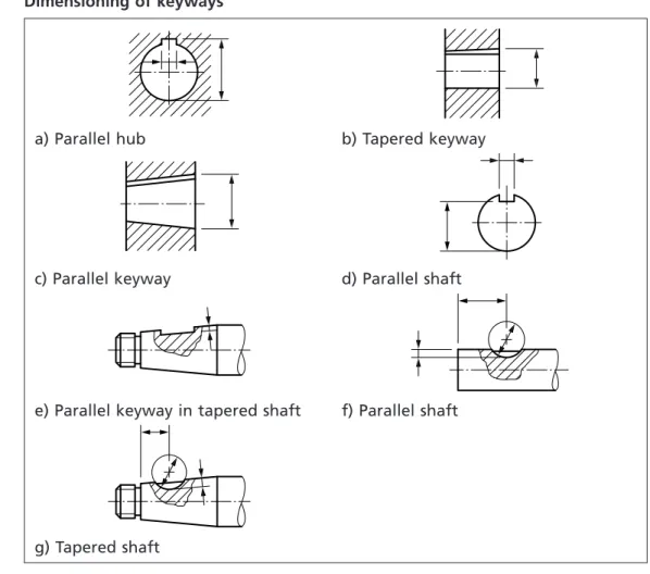
Figure 15 – Dimensioning of keyways 31
Figure 16 – Interrelationship of the geometrical feature definitions 32
Figure 17 – Example of tolerance zone constrained in orientation from a datum 34
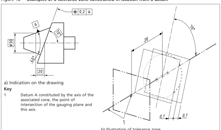
Figure 18 – Examples of a tolerance zone constrained in location from a datum 34
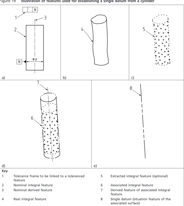
Figure 19 – Illustration of features used for establishing a single datum from a cylinder 36
Figure 20 – Datum feature indicator 41
Figure 21 – Single datum target frame 42
Figure 22 – Datum target symbol 42
Figure 23 – Non-closed datum target line 42
Figure 24 – Closed datum target line 43
Figure 25 – Datum target area 43
Figure 26 – Indicator for single datum target point 43
Figure 27 – Indicator for single datum target line 44
Figure 28 – Indicator for single datum target surface 44
Figure 29 – Location of datum letter symbol(s) in the tolerance frame 44
Figure 30 – Attachment of a datum indicator for a single feature considered a feature of size 46
Figure 31 – Attachment of a datum indicator for a single feature not considered a feature of size 47
Figure 32 – Indication of datums established from datum targets 47
Figure 33 – Simplification of drawing indication when there is only one datum target area 48
Figure 34 – Examples of single datums established from a complete cylinder, a portion of a cylinder or with a contacting feature 49
Figure 35 – Indication of dimension of a circular/square area 50
Figure 36 – Indication of dimensions of a rectangular area 50
Figure 37 – Examples of indication of datums in the tolerance frame 51
Figure 38 – Examples of complementary indication 52
Figure 39 – Example of application of modifier on the secondary datum 53
Figure 40 – Meaning of the specification given in Figure 39 53
Figure 41 – Tolerance applying to more than one feature 57
Figure 42 – Indications qualifying the form of the feature within the tolerance zone 57
Figure 43 – Requirements given in tolerance frames one under the other 57
Figure 44 – Arrowhead terminating on the outline of the feature or as an extension 58
Figure 45 – Arrowhead terminating as an extension of the dimension line 58
Figure 46 – Width of tolerance zone applying to the specified geometry 59
Figure 47 – With of tolerance zone, otherwise indicated 59
Figure 48 – Orientation of the width of a positional tolerance zone 60
Figure 49 – Orientation of the width of an orientation tolerance zone 60
Figure 50 – Tolerances perpendicular to each other 60
Figure 51 – Cylindrical and circular tolerance zones 61
Figure 52 – Tolerance zones applied to separate features 61
Figure 53 – Single tolerance zone applied to separate features 61
Figure 54 – Examples of the use of the “all around” symbol 62
Figure 55 – Examples of “MD” and “LD” 62
Figure 56 – TED, enclosed in a frame 63
Figure 57 – Examples of tolerances of the same characteristic 63
Figure 58 – Tolerance applied to a restricted part of a feature 64
Figure 59 – Projected tolerance zone 64
Figure 60 – Indication of the maximum material requirement 65
Figure 61 – Indication of the least material requirement 65
Figure 62 – Free state condition 65
Figure 63 – Use of several specification modifiers 65
Figure 64 – BS 8888 independency system symbol 69
Figure 65 – BS 8888 dependency system symbol 70
Figure E.1 – Model of the relationship between specification, verification and the actual work piece 87
Figure E.2 – The link between design intent and metrology 88
List of tables
Table 1 – Sizes of trimmed and untrimmed sheets and the drawing spaceA) 5
Table 2 – Number of fields 6
Table 3 – Basic types 7
Table 4 – Identifying data fields in the title block 8
Table 5 – Descriptive data fields in the title block 8
Table 6 – Administrative data fields in the title block 9
Table 7 – Scales 10
Table 8 – Permissible deviations for linear dimensions except for broken edges 11
Table 9 – Permissible deviations for broken edges (external radii and chamfer heights) 11
Table 10 – Permissible deviations of angular dimensions 11
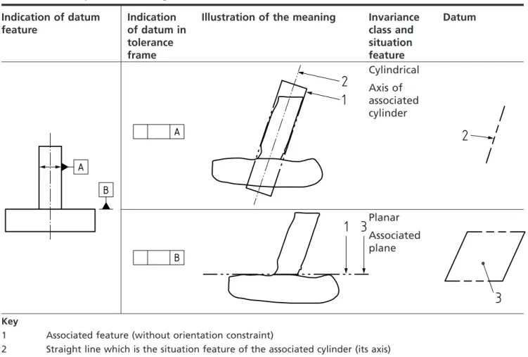
Table 11 – Datum features and datum target symbols 33
Table 12 – Interpretation of single datum references 37
Table 13 – Common datum or datum system taken from a cylinder and a plane 39
Table 14 – Common datum or datum system taken from two cylinders 40
Table 15 – Datum system taken from two cylinders and a plane 41
Table 16 – Symbols for geometrical characteristics 55
Table 17 – Additional symbols 56
Table C.1 – Examples of geometrical tolerancing 79
Figure E.3 – The duality principle 90
Summary of pages
This document comprises a front cover, an inside front cover, pages i to iv, pages 1 to 92, an inside back cover and a back cover.
Foreword
Publishing information
This British Standard is published by BSI and came into effect on
31 December 2011. It was prepared by Subcommittee TDW/4/8,BS 8888 – Technical product specification, under the authority of Technical Committee TDW/4,Technical product realization. A list of organizations represented on this committee can be obtained on request to its secretary.
Supersession
This British Standard supersedes BS 8888:2008, which is withdrawn.
Information about this document
This sixth edition of the standard is a full revision. It introduces relevant international standards published since the 2008 edition. It also incorporates more fully than previous editions some of the fundamental requirements of the key international standards relevant to the preparation of technical product specifications, such as BS EN ISO 1101 and BS EN ISO 5459. It is hoped that UK industry will find this edition of BS 8888 more user friendly than previous editions. It aims to help organizations better understand and implement the full complement of International Standards developed by ISO/TC 213,Geometrical product specifications and verification, and ISO/TC 10,Technical product documentation.
Relationship with other publications
The function of BS 8888 is to draw together, in an easily accessible manner, the full complement of international standards relevant to the preparation of technical product specifications. However, it is not the intention for BS 8888 to be a “stand-alone” standard. TDW/4 is responsible for a suite of related national standards which include the various parts of the BS 8887 series, BS 88891)and
PD 68888, a new training document.
BS 8888 was taken up by the Ministry of Defence in 2006 as part of its DEF-STAN for defence project specification.
Presentational conventions
The provisions of this standard are presented in roman (i.e. upright) type. Its requirements are expressed in sentences in which the principal auxiliary verb is “shall”.
Commentary, explanation and general informative material is presented in smaller italic type, and does not constitute a normative element.
All dimensions shown in the figures in this British Standard are in millimetres.
Contractual and legal considerations
This publication does not purport to include all the necessary provisions of a contract. Users are responsible for its correct application.
Compliance with a British Standard cannot confer immunity from legal obligations.
1) ln development.
1 Scope
This British Standard implements the ISO system for technical product documentation and specification.
The ISO system is defined in a large number of interlinked and related international standards which are referenced from within BS 8888.
The purpose of this British Standard is to facilitate the use of the ISO system by providing:
• an index to the international standards which comprise the ISO system, referencing them according to their area of application;
• key elements of the ISO standards to facilitate their application;
• references to additional British and European Standards where they provide information or guidance over and above that provided by ISO standards; and
• commentary and recommendations on the application of the standards where this is deemed useful.
The requirements refer to International and European Standards which have been implemented as British Standards either in the BS EN, BS EN ISO, BS ISO series or as International Standards re-numbered as British Standards.
Annex A (normative) contains a list of normative references, indispensible for the application of this British Standard.
Annex B (informative) contains a list of informative references.
Annex C (normative) contains a set of examples of geometrical tolerances and associated requirements.
Annex D (normative) contains requirements for enhanced security.
Annex E (informative) provides a summary report on the concepts that have underwritten the development of technical product specification (TPS) and its primary constituent, geometrical product specification (GPS), to date and discusses some of the drivers for future change.
2 Normative references
Normative references are indispensable for the application of this document. A full list is contained in Annex A.
3 Terms and definitions
For the purposes of this British Standard, the following terms and definitions apply, together with those given in
BS EN ISO 10209 Technical product documentation – Vocabulary - Terms relating to technical drawings, product definition and related products
BS EN ISO 14660-1 Geometrical product specification (GPS) – Geometrical features – Part 1: General terms and definitions
3.1
date of acceptance
point in time at which all interested parties agree that the technical product specification is to be considered finalized to the extent that manufacturing can commence
NOTE 1 This might be identified by other terms, e.g. “date of issue”.
NOTE 2 For the implications of the date of acceptance see4.2.3.
3.2
ISO GPS system
geometrical product specification and verification system developed in ISO by ISO/TC 213
3.3
technical product documentation (TPD)
means of conveying all or part of a design definition or specification of a product
3.4
technical product specification (TPS)
technical product documentation comprising the complete design definition and specification of a product for manufacturing and verification purposes
NOTE A TPS, which might contain drawings, 3-D models, parts lists or other documents forming an integral part of the specification, in whatever format they might be presented, might consist of one or more TPDs.
4 Standards underpinning BS 8888
4.1
Fundamental TPS principles
4.1.1
General
The following standards shall be applied as “global” standards in support of BS 8888.
ISO/IEC Guide 98-3
Guide to the expression of uncertainty in measurement (GUM)
ISO/IEC Guide 99 International vocabulary of metrology – basic and general concepts and associated terms (VIM)
The following principles shall always be applied where conformity with BS 8888 is claimed.
4.1.2
General principles of specification
A TPS shall document the criteria that the manufactured product has to satisfy.
NOTE 1 The TPS might include requirements of individual manufactured components, where necessary.
NOTE 2 The TPS might include additional information required for the manufacture, verification, maintenance and disposal of the product. NOTE 3 Criteria might include requirements relating to the appearance,
transportation, storage, maintenance, assembly, disassembly, recycling and disposal of the product, as well as its performance and reliability in use.
Sizes, geometrical relationships and tolerances which are necessary for the correct functioning or location of a component or assembly shall be specified through the use of datums, dimensions and tolerances.
NOTE 4 Selection of datum features which are not related to the function or location of a component or assembly results in the need for tighter tolerances.
A TPS shall provide sufficient information to avoid ambiguity of interpretation.
NOTE 5 A TPS is not complete if there is more than one possible interpretation of the specification.
A TPS shall provide sufficient information for the product to be manufactured, but shall not unnecessarily constrain manufacturing methods.
NOTE 6 A particular manufacturing process which has been tested and approved for the production of a safety-critical component is an example of a situation where there is a requirement to specify the manufacturing method.
A TPS shall provide sufficient information for the verification of each element of the specification, but shall not unnecessarily constrain verification methods. A TPS shall provide all the information necessary for the manufacture and verification of the product, or state where that information can be found.
NOTE 7 This might be achieved through the use of notes and references to other standards or documents.
4.1.3
Acceptance date principle
A TPS shall always be interpreted according to those versions of standards which governed its interpretation on its acceptance date.
NOTE What is not specified in a TPS at the date of acceptance cannot be required.
4.1.4
Reference condition principle
Unless otherwise stated, all geometrical forms, sizes and tolerances for a work-piece given in a TPS shall be considered to apply at 20 °C.
NOTE 1 See BS EN ISO 1.
Unless otherwise stated, all geometrical sizes, forms and tolerances for a workpiece given in a TPS shall be considered to apply in the absence of any external forces (including gravity).
NOTE 2 This is of particular importance when aligning and/or measuring large and/or flexible constructions. See22.2.
4.2
Implied annotation
The following rules shall govern the use and interpretation of implied annotation on engineering drawings.
NOTE A dimension may be implied and not indicated on a drawing in the following circumstances, so long as there is no risk of misinterpretation.
a) Where two features are aligned, there is no requirement to indicate a linear dimension of 0 or an angular dimension of 0°.
b) Where two features are parallel to each other, there is no requirement to indicate an angular dimension of 0° or 180°.
c) Where two features are at 90° to each other, there is no requirement to indicate an angular dimension of 90°.
d) Where several features are equispaced around a pitch circle (see BS ISO 129-1), there is no requirement to indicate an angular dimension, although it might be advisable to do so. Terms such as “equispaced”, “equally spaced”, etc. shall not be used.
e) Where not otherwise indicated, holes are considered as through holes. If the features concerned have their locations and/or orientations controlled through the use of geometrical tolerances, then the implied dimensions shall be taken as Theoretically Exact Dimensions (TEDs; see BS EN ISO 1101).
If the features concerned have their locations and/or orientations controlled through the use of +/− or limit tolerances, then the implied dimensions shall also be toleranced. In the absence of other indications, they shall be subject to a general tolerance, or else the TPS would remain incomplete.
Tolerances shall never be implied, and shall always be indicated. Datums shall never be implied, and shall always be indicated.
Section 1: Technical product documentation
5 Types of documentation
5.1
General
COMMENTARY ON5.1
The careful targeting of TPDs to known or intended users can greatly assist the accuracy with which the specification is converted into the final product.
While precision and avoidance of ambiguity shall always be paramount, the means employed to convey this information shall be seen to match the
capability, or potential capability, of the available or achievable manufacturing facility.
NOTE Specification beyond this level is unlikely to produce satisfactory results and can often prove expensive, both in terms of the cost of the over-specification itself and in terms of inadequate or unacceptable product.
5.2
Presentation media
5.2.1
General
The presentation of the drawings shall conform to the following standards, as appropriate.
BS EN ISO 5457 Technical product documentation – Sizes and layout of drawing sheets
BS EN ISO 7200:2004Technical product documentation – Data fields in title blocks and document headers
BS ISO 7573 Technical drawings – Parts lists
5.2.2
Format
Drawing sheets and other documents shall be presented in one of the following formats.
a) Landscape: intended to be viewed with the longest side of the sheet horizontal.
b) Portrait: intended to be viewed with the longest side of the sheet vertical.
NOTE Contrary to BS EN ISO 5457, A4 sheets may be used in landscape or portrait mode.
6 Drawing sheets
6.1
Sizes
As stated in the requirements of BS EN ISO 5457, the original drawing shall be made on the smallest sheet permitting the necessary clarity and resolution.
NOTE 1 The preferred sizes of the trimmed and untrimmed sheets as well as the drawing space of the main ISO-A series (see BS EN ISO 216) are given in Table 1. NOTE 2 See BS EN ISO 5457 for more information about drawing sheets.
NOTE 3 The range of sheet sizes chosen could be rationalized through the use of a variety of new scales. See Clause8.
Table 1 Sizes of trimmed and untrimmed sheets and the drawing space Designation Trimmed sheet
(T)
Drawing space Untrimmed sheet (U)
a1B) b1B) a2 ±0.5 b2 ±0.5 a5 ±2 b5 ±2 A0C) 841 1 189 821 1 159 880 1 230 A1 594 841 574 811 625 880 A2 420 594 400 564 450 625 A3 297 420 277 390 330 450 A4 210 297 180 277 240 330 A)Dimensions in millimetres. B)For tolerances see BS EN ISO 216. C)For sizes > A0 see BS EN ISO 216.
6.2
Graphical features
6.2.1
Title block
NOTE 1 For the dimensions and layout of title blocks, see BS EN ISO 7200.
Sizes A0 to A3 shall be used in landscape orientation only (Figure 1) and the location of the title block shall be situated in the bottom right-hand corner of the drawing space.
NOTE 2 A4 sheets may be used in landscape or portrait orientation.
For the size A4, the title block shall be situated in the bottom right-hand corner when used in landscape orientation, or the shorter (bottom) part of the drawing space when used in portrait orientation.
Figure 1 Size A4 to A0
6.2.2
Borders and frame
Borders enclosed by the edges of the trimmed sheet and the frame limiting the drawing space shall be provided with all sizes. The border shall be 20 mm wide on the left edge, including the frame and it can be used as a filing margin. All other borders shall be 10 mm wide.
The frame for limiting the drawing space shall be executed with continuous wide lines.
6.2.3
Grid reference system
The sheets shall be divided into fields in order to permit easy location of details, additions, revisions, etc. on the drawing. The individual fields shall be referenced from the top downwards with capital letters (I and O shall not be used) and from left to right with numerals. For the size A4, they shall be located only at the top and the right side.
The size of letters and characters shall be 3.5 mm. The length of the fields shall be 50 mm, starting at the axes of symmetry of the trimmed size (centring marks).
NOTE The number of fields depends on the size (see Table 2).
The differences resulting from the division shall be added to the fields at the corners. The letters and numerals shall be placed in the grid reference border, and shall be written in vertical characters according to BS EN ISO 3098-2. The grid reference system lines shall be executed with continuous narrow lines.
Table 2 Number of fields
Designation A0 A1 A2 A3 A4
Long side 24 16 12 8 6
Short side 16 12 8 6 4
6.3
Line types and line widths
6.3.1
Types of line
COMMENTARY ON6.3.1
Table 3 shows the basic types of line. See BS EN ISO 128-20 for more information on lines.
6.3.2
Line width
According to the requirements of BS EN ISO 128-20, the width,d, of all types of line shall be one of the following depending on the type and size of drawing. • 0,13 mm, 0,18 mm, 0,25 mm, 0,35 mm, 0,5 mm, 0,7 mm, 1 mm, 1,4 mm,
2 mm.
NOTE 1 The widths of extra wide, wide and narrow lines are in the ratio 4:2:1. NOTE 2 For mechanical engineering drawings, four line types – continuous, dashed, chain (long-dashed dotted) and phantom (long-dashed double-dotted) – in two line thicknesses (typically 0,35 mm and 0,7 mm) are sufficient for most purposes.
The line width of any one line shall be constant throughout the whole line.
6.4
Colours
According to the requirements of BS EN ISO 128-20, lines shall be drawn black or white depending on the background. Other standardized colours may also be used for drawing standardized lines, and in this case, the meaning of the colours shall be explained.
7 Title block
7.1
General
COMMENTARY ON7.1
A condition for the transfer and presentation of information is that data fields be defined with regard to field name, content of information and number of
characters.
When document management systems are used, the conditions that apply to the data fields differ to a certain extent from those that apply in non-computerized document management. The same data field can, for example, be part of several different types of document simultaneously, as it is possible to process the contents by computer in connection with retrieval, revision, communication, etc.
For more information on title blocks, see BS EN ISO 7200.
Table 3 Basic types
No. Representation Description
01 continuous line
02 dashed line
03 dashed spaced line
04 long-dashed dotted line
05 long-dashed double-dotted line
06 long-dashed triplicate-dotted line
07 dotted line
08 long-dashed short-dashed line
09 long-dashed double short-dashed line
10 dashed dotted line
11 double-dashed dotted line
12 dashed double-dotted line
13 double-dashed double-dotted line
14 dashed triplicate-dotted line
15 double-dashed triplicate-dotted line
If the functions of the system are to behave in a satisfactory way, the
information shall be entered in the proper data field and in a correct manner.
NOTE For this reason, computer-based systems commonly contain more permanent data fields than paper-based systems.
The number of data fields in the title block shall be limited to a minimum, while other data fields shall be handled dynamically and presented outside the title block only when used, e.g. scale, projection symbol, general tolerance and surface texture requirements.
7.2
Data fields in the title block – Identifying data fields
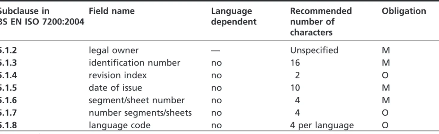
The identifying data fields in the title block shall be in accordance with Table 4, which is from BS EN ISO 7200:2004.
Table 4 Identifying data fields in the title block Subclause in
BS EN ISO 7200:2004
Field name Language
dependent
Recommended number of characters
Obligation
5.1.2 legal owner — Unspecified M
5.1.3 identification number no 16 M
5.1.4 revision index no 2 O
5.1.5 date of issue no 10 M
5.1.6 segment/sheet number no 4 M
5.1.7 number segments/sheets no 4 O
5.1.8 language code no 4 per language O
M = mandatory O = optional
Descriptive data fields shall be as specified in Table 5, which is taken from BS EN ISO 7200:2004.
Table 5 Descriptive data fields in the title block Subclause in
BS EN ISO 7200:2004
Field name Language
dependent Recommended number of characters Obligation 5.2.2 title yes 25/30 A) M
5.2.3 supplementary title yes 2 × 25/30A) O
M = mandatory O = optional
A)30 to support two-byte-character language such as Japanese or Chinese.
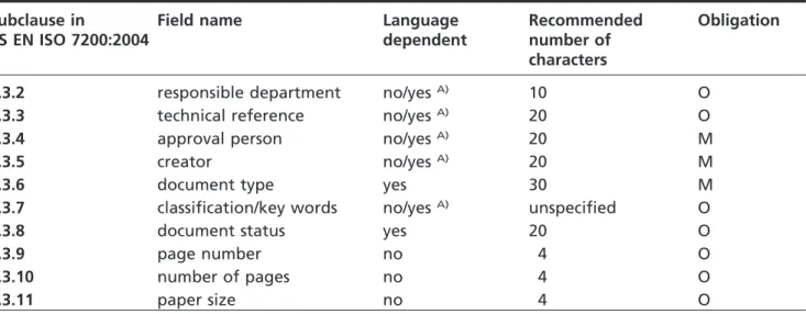
Administrative data fields shall be as specified in Table 6, which is taken from BS EN ISO 7200:2004.
Table 6 Administrative data fields in the title block Subclause in
BS EN ISO 7200:2004
Field name Language
dependent
Recommended number of characters
Obligation
5.3.2 responsible department no/yesA) 10 O
5.3.3 technical reference no/yesA) 20 O
5.3.4 approval person no/yesA) 20 M
5.3.5 creator no/yesA) 20 M
5.3.6 document type yes 30 M
5.3.7 classification/key words no/yesA) unspecified O
5.3.8 document status yes 20 O
5.3.9 page number no 4 O
5.3.10 number of pages no 4 O
5.3.11 paper size no 4 O
M = mandatory O = optional
A)“Yes” to support presentation in different types of alphabet.
7.3
Title block arrangement
COMMENTARY ON7.3
For the position of title blocks on technical drawings, see BS EN ISO 5457. For text documents, there are no ISO requirements. For examples of title block arrangements for use on drawings as well as text documents, see Figures 2 and 3.
As specified by the requirements of BS EN ISO 7200, the total width shall be 180 mm to fit an A4 sheet, with the left margin being 20 mm and the right margin 10 mm.
Figure 2 Title block in compact form
Figure 3 Title block with person name fields on additional line
8 Scales
8.1
General
The recommended scales for use on technical drawings shall be as specified in Table 7.
Table 7 Scales
Category Recommended scales
Enlargement scales 50:1 20:1 10:1 5:1 2:1 Full size Reduction scales 1:2 1:5 1:10 1:20 1:50 1:100 1:200 1:500 1:1 000 1:2 000 1:5 000 1:10 000 The scale to be chosen for a drawing shall depend upon the complexity of the object to be depicted and the purpose of the representation. In all cases, the selected scale shall be large enough to permit easy and clear interpretation of the information depicted. The scale and the size of the object, in turn, shall decide the size of the drawing.
Details that are too small for complete dimensioning in the main representation shall be shown adjacent to the main representation in a separate detail view (or section) which is drawn to a larger scale.
NOTE 1 It is recommended that the scales in Table 7 are used wherever possible. However, with the advent of CAD systems and the ability to view drawings electronically at any size, the importance of using a standard range of scales has diminished. Where the recommended scales cannot be applied, intermediate scales may be selected.
3D models produced on CAD systems shall always be produced at 1:1.
NOTE 2 For more information on scales, see BS EN ISO 5455.
9 General tolerances
9.1
General
COMMENTARY ON9.1
All features on component parts always have a size and a geometrical shape. For the deviation of size and for the deviations of the geometrical characteristics (form, orientation and location) the function of the part requires limitations which, when exceeded, impair this function.
The tolerancing on the drawing shall be complete to ensure that the elements of size and geometry of all features are controlled, i.e. nothing shall be implied or left to judgement in the workshop or in the inspection department.
NOTE 1 The use of general tolerances for size and geometry simplifies the task of ensuring that the prerequisites are met.
NOTE 2 See BS EN 22768 for more information on general tolerances.
9.2
General tolerances for linear dimensions
When use is made of BS EN 22768-1 (ISO 2768-1) for general tolerances, tolerances for dimensions shall be as given in Table 8, Table 9 and Table 10.
Table 8 Permissible deviations for linear dimensions except for broken edges Tolerance class Permissible deviations for basic size range Designa-tion Description 0,5A) up to 3 over 3 up to 6 over 6 up to 30 over 30 up to 120 over 120 up to 400 over 400 up to 1 000 over 1 000 up to 2 000 over 2 000 up to 4 000 f fine ±0,05 ±0,05 ±0,1 ±0,15 ±0,2 ±0,3 ±0,5 — m medium ±0,1 ±0,1 ±0,2 ±0,3 ±0,5 ±0,8 ±1,2 ±2 c coarse ±0,2 ±0,3 ±0,5 ±0,8 ±1,2 ±2 ±3 ±4 v very coarse — ±0,5 ±1 ±1,5 ±2,5 ±4 ±6 ±8
A)For nominal sizes below 0,5 mm, the deviations shall be indicated adjacent to the relevant nominal size(s). NOTE Values in millimetres.
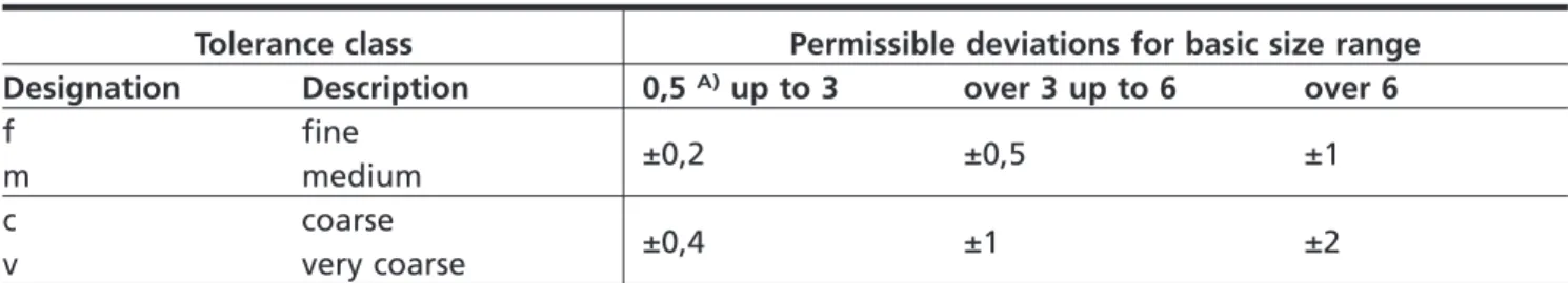
Table 9 Permissible deviations for broken edges (external radii and chamfer heights) Tolerance class Permissible deviations for basic size range
Designation Description 0,5A)up to 3 over 3 up to 6 over 6
f fine ±0,2 ±0,5 ±1 m medium c coarse ±0,4 ±1 ±2 v very coarse
A)For nominal sizes below 0,5 mm, the deviations shall be indicated adjacent to the relevant nominal size(s). NOTE Values in millimetres.
Table 10 Permissible deviations of angular dimensions
Tolerance class Permissible deviations for ranges of lengths, in millimetres, of the shorter side of the angle concerned
Designation Description up to 10 over 10 up to 50 over 50 up to 120 over 120 up to 400 over 400 f fine ±1° ±0°30' ±0°20' ±0°10' ±0°5' m medium c coarse ±1°30' ±1° ±0°30' ±0°15' ±0°10' v very coarse ±3° ±2° ±1° ±0°30' ±0°20' COMMENTARY ON9.2
If reference to BS EN 22768-1 (ISO 2768-1) for general tolerances is inappropriate, general tolerance notes could be used to apply a common tolerance to many of the features on a drawing. The example shown in Figure 4 illustrates the wide field of application of this system.
Figure 4 Examples of general tolerance notes
9.3
General geometrical tolerances
COMMENTARY ON9.3
Due to the inherent risk of unintentionally over-specifying form and orientation controls that can result from the use of general geometrical tolerances, reference to BS EN ISO 22768-2 is inadvisable.
10 Conventions for arrangement of views on a TPD
10.1
General
Three main conventions shall be used for arranging the views on a TPD: a) labelled views;
b) first angle orthographic projection; c) third angle orthographic projection.
NOTE 1 The order of this list is not meant to indicate a preference. NOTE 2 Other projection methods exist. See BS EN ISO 5456 (all parts).
10.2
Choice of views
When views (including sections and sectional views) are needed, these shall be selected according to the following principles.
a) The number of views (and sections and sectional views) shall be limited to the minimum necessary but shall be sufficient to fully delineate the object without ambiguity.
b) The need for hidden outlines and edges shall be avoided. c) The unnecessary repetition of a detail shall be avoided.
10.3
Labelled view method
As specified by the requirements of BS ISO 128-30, the most informative view of an object shall be used as the front or principal figure, taking into
consideration, for example, its functioning position, position of manufacturing or mounting. Each view, with the exception of the front or principal figure (view, plan, principal figure) shall be given clear identification with a capital letter, repeated near the reference arrow needed to indicate the direction of the viewing for the relevant view. Whatever the direction of viewing, the capital letter shall always be positioned in normal relation to the direction of reading, and be indicated either above or on the right side of the reference arrow.
The capital letters identifying the referenced views shall be placed immediately above the relevant views (see Figure 5).
Figure 5 Labelled view method
10.4
First angle projection method
10.4.1
General
NOTE A more detailed description of the first angle projection method is to be found in BS ISO 128-30 and in BS EN ISO 5456-2.
With reference to the front view (a), the other views shall be arranged as follows (see Figure 6).
• The view from above (b) shall be placed underneath. • The view from below (e) shall be placed above.
• The view from the left (c) shall be placed on the right. • The view from the right (d) shall be placed on the left.
• The view from the rear (f) shall be placed on the left or right, as convenient.
Figure 6 First angle projection method
10.4.2
First angle projection method – Graphical symbol
As specified by the requirements of BS ISO 128-30, the graphical symbol for the first angle projection method shall be as shown in Figure 7.
The proportions and dimensions of this graphical symbol shall be as specified in BS ISO 128-30.
Figure 7 First angle projection method – Graphical symbol
10.5
Third angle projection method
10.5.1
General
NOTE A more detailed description of the third angle projection method is to be found in BS ISO 128-30 and in BS EN ISO 5456-2.
10.5.2
Third angle projection method
With reference to the front view (a), the other views shall be arranged as follows (see Figure 8).
• The view from above (b) shall be placed above. • The view from below (e) shall be placed underneath. • The view from the left (c) shall be placed on the left. • The view from the right (d) shall be placed on the right.
• The view from the rear (f) shall be placed on the left or right, as convenient.
Figure 8 Third angle projection method
10.5.3
Third angle projection method – Graphical symbol
As specified by the requirements of BS ISO 128-30, the graphical symbol for the third angle projection method shall be as shown in Figure 9.
The proportions and dimensions of this graphical symbol shall be as specified in BS ISO 128-30.
Figure 9 Third angle projection method – Graphical symbol
11 Mechanical engineering drawings
11.1
General
As specified by the requirements of BS ISO 128-44, ribs, fasteners, shafts, spokes of wheels and the like shall not be cut in longitudinal sections, and shall
therefore not be represented as sections.
NOTE 1 Like views, sections might be shown in a position other than that indicated by the arrows for the direction of their viewing.
NOTE 2 A section in one plane is shown in Figure 10.
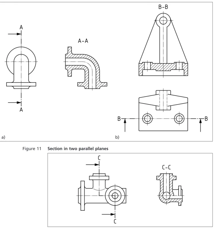
NOTE 3 A section in two parallel planes is shown in Figure 11. NOTE 4 A section in three contiguous planes in shown in Figure 12.
Figure 10 Section in one plane
a) b)
Figure 11 Section in two parallel planes
Figure 12 Section in three contiguous planes
12 Diagram
COMMENTARY ON CLAUSE12
The function of a system, or the relationship between component parts, might be depicted in a diagram employing simplified representations, as recommended in the following standards.
BS 5070-1 Engineering diagram drawing practice –
Part 1: Recommendations for general principles
BS 5070-3 Engineering diagram drawing practice –
Part 3: Recommendations for mechanical/fluid flow diagrams
BS 5070-4 Engineering diagram drawing practice – Part 4: Recommendations for logic diagrams
BS EN 61082-2 Preparation of documents used in electrotechnology – Part 2: Function-oriented diagrams
BS EN ISO 3952-1 Kinematic diagrams – Graphical symbols – Part 1
BS EN ISO 3952-2 Kinematic diagrams – Graphical symbols – Part 2
BS EN ISO 3952-3 Kinematic diagrams – Graphical symbols – Part 3
BS ISO 15519-1 Specification for diagrams for process industry – Part 1: General rules
12.1
Designation
As specified by the requirements of BS EN ISO 5455, the complete designation of scale shall consist of the word “SCALE” (or its equivalent in the language used on the drawing) followed by the indication of its ratio as follows:
• SCALE 1 : 1 for full size;
• SCALE X : 1 for enlargement scales; • SCALE 1 : X for reduction scales.
NOTE If there is no likelihood of misunderstanding, the word “SCALE” can be omitted.
12.2
Inscription
The designation of the scale used on the drawing shall be inscribed in the title block of the drawing.
Where it is necessary to use more than one scale on the drawing, the main scale only shall be inscribed in the title block, and all other scales adjacent to the item reference number of the part concerned, or adjacent to the reference letter of a detail view (or section).
13 Lines, arrows and terminators
13.1
Lines and terminators
Lines shall conform to the following standards, as appropriate.
BS EN ISO 128-20 Technical drawings – General principles of presentation – Part 20: Basic conventions for lines
BS EN ISO 128-21 Technical drawings – General principles of presentation – Part 21: Preparation of lines by CAD systems
BS ISO 128-22 Technical drawings – General principles of presentation – Part 22: Basic conventions and applications for leader lines and reference lines
BS ISO 128-23 Technical drawings – General principles of presentation – Part 23: Lines on construction drawings
BS ISO 128-24 Technical drawings – General principles of presentation – Part 24: Lines on mechanical engineering drawings
BS ISO 128-25 Technical drawings – General principles of presentation – Part 25: Lines on shipbuilding drawings
13.2
Lines, terminators and origin indicators
Arrows and terminators composed of lines shall conform to the following standard.
BS ISO 129-1 Technical drawings – Indications of dimensions and tolerances – Part 1: General principles
14 Lettering
14.1
General
Lettering shall conform to the following standards, as appropriate.
BS EN ISO 3098-0 Technical product documentation – Lettering – Part 0: General requirements
BS EN ISO 3098-2 Technical product documentation – Lettering – Part 2: Latin alphabet, numerals and marks
BS EN ISO 3098-3 Technical product documentation – Lettering – Part 3: Greek alphabet
BS EN ISO 3098-4 Technical product documentation – Lettering –
Part 4: Diacritical and particular marks for the Latin alphabet
BS EN ISO 3098-5 Technical product documentation – Lettering – Part 5: CAD lettering of the Latin alphabet, numerals and marks
BS EN ISO 3098-6 Technical product documentation – Lettering – Part 6: Cyrillic alphabet
14.2
Notes
When a landscape-format drawing sheet is used in its normal orientation, with the title block at the bottom right-hand corner, notes shall be written with the text parallel to the long side of the sheet. When a landscape-format drawing sheet is used in portrait orientation, the title block shall be located at the left-hand side and notes shall be written with the text parallel to the short side of the sheet.
NOTE 1 Notes of a general nature should, wherever practicable, be grouped together and not distributed over the drawing. Notes relating to specific details should appear near the relevant feature, but not so near as to crowd the view. NOTE 2 Underlining of notes is not recommended. Where emphasis is required, larger characters should be used.
NOTE 3 It is recommended that capital lettering is used wherever possible.
15 Projections
Projections shall conform to one of the following standards. BS EN ISO 5456-2 Technical drawings – Projection methods –
Part 2: Orthographic representations
BS EN ISO 5456-3 Technical drawings – Projection methods – Part 3: Axonometric representations
BS ISO 5456-4 Technical drawings – Projection methods – Part 4: Central projection
BS EN ISO 10209 Technical product documentation
NOTE BS EN ISO 5456-1 contains a survey of the various projection methods.
16 Views
16.1
General
Views shall conform to the following standards.
BS ISO 128-30 Technical drawings – General principles of presentation – Part 30: Basic conventions for views
BS ISO 128-34 Technical drawings – General principles of presentation – Part 34: Views on mechanical engineering drawings
16.2
Auxiliary views
Where true representation of features is necessary, but cannot be achieved on the orthographic views, the features shall be shown in projected auxiliary views. An example is shown in Figure 13.
Figure 13 Auxiliary view showing true shape of inclined surface
17 Sections
Sections shall conform to the following standards.
BS ISO 128-40 Technical drawings – General principles of presentation – Part 40: Basic conventions for cuts and sections
BS ISO 128-44 Technical drawings – General principles of presentation – Part 44: Sections on mechanical engineering drawings
BS ISO 128-50 Technical drawings – General principles of presentation – Part 50: Basic conventions for representing areas on cuts and sections
NOTE ISO 128-44 and ISO 128-50 contain presentational defects in some figures (e.g. line types, line thickness, terminators and letter heights), which have,
unavoidably, been carried forward to the BS implementations. It is stressed that the text of these standards is technically correct and users should, therefore, regard the figures as illustrations only.
18 Symbols and abbreviations
18.1
General
Abbreviations (text equivalents) shall be the same in the singular and plural. Full stops shall not be used except where the abbreviation forms a word (e.g. NO. as an abbreviation for “number”).
NOTE Where possible, abbreviations should be avoided (see 18.2).
Symbols used for physical quantities and units of measurement shall conform to the following standards, as appropriate.
BS ISO 80000-1 Quantities and units – Part 1: General
BS ISO 80000-2 Quantities and units – Part 2: Mathematical signs and symbols to be used in the natural sciences and technology
BS ISO 80000-3 Quantities and units – Part3: Space and time
BS ISO 80000-4 Quantities and units – Part4: Mechanics
BS ISO 80000-5 Quantities and units – Part 5: Thermodynamics
BS EN ISO 80000-6 Quantities and units – Part 6: Electromagnetism
BS ISO 80000-7 Quantities and units – Part 7: Light
BS EN ISO 80000-8 Quantities and units – Part 8: Acoustics
BS ISO 80000-9 Quantities and units – Part 9: Physical chemistry and molecular physics
BS ISO 80000-10 Quantities and units – Part 10: Atomic and nuclear physics
BS ISO 80000-11 Quantities and units – Part 11: Characteristic numbers
BS ISO 80000-12 Quantities and units – Part 12: Solid state physics
BS EN 80000-13 Quantities and units – Part 13: Information science and technology
BS EN 80000-14 Quantities and units – Part 14: Telebiometrics related to human physiology
18.2
Standard symbols and abbreviations
COMMENTARY ON18.2
In the existing environment of outsourcing across national borders, every effort is being made to make the use of GPS, independent of language through the adoption of standard symbology. It is for this reason that the continued use of abbreviations is deprecated. Where particular specification requirements cannot be expressed using the available GPS system, full text description should be employed. It is suggested that where such a requirement occurs frequently, this be drawn to the attention of the relevant ISO committee through the appropriate BSI Technical Committee.
For diagrams used in technical applications, a library of harmonized graphical symbols has been developed with close cooperation between ISO and IEC. This is published in the following series of standards and it is recommended that they be applied wherever practicable to improve the universal applicability of the TPS.
BS ISO 14617-1 Graphical symbols for diagrams – Part 1: General information and indexes
BS ISO 14617-2 Graphical symbols for diagrams – Part 2: Symbols having general application.
BS ISO 14617-3 Graphical symbols for diagrams – Part 3: Connections and related devices
BS ISO 14617-4 Graphical symbols for diagrams – Part 4: Actuators and related devices
BS ISO 14617-5 Graphical symbols for diagrams – Part 5: Measurement and control devices
BS ISO 14617-6 Graphical symbols for diagrams – Part 6: Measurement and control functions.
BS ISO 14617-7 Graphical symbols for diagrams – Part 7: Basic mechanical components
BS ISO 14617-8 Graphical symbols for diagrams – Part 8: Valves and dampers.
BS ISO 14617-9 Graphical symbols for diagrams – Part 9: Pumps, compressors and fans
BS ISO 14617-10 Graphical symbols for diagrams – Part 10: Fluid power converters
BS ISO 14617-11 Graphical symbols for diagrams – Part 11: Devices for heat transfer and heat engines
BS ISO 14617-12 Graphical symbols for diagrams – Part 12: Devices for separating purification and mixing
Symbols appropriate to technical product specification are provided and detailed throughout the suite of documents cross-referenced from this British Standard and these shall be used where appropriate.
NOTE 1 It is strongly recommended that abbreviations not be used.
Where, in particular technical fields, certain abbreviations are in common use and generally understood, it is accepted that these may continue to be used but new abbreviations shall not be introduced.
NOTE 2 Former practice has resulted in certain abbreviations becoming accepted as symbols and these should not be considered to provide precedence for the
proliferation of abbreviations.
19 Representation of features
Conventions used for the representation of features shall conform to the following standards, as appropriate.
BS EN ISO 4063 Welding and allied processes – Nomenclature of processes and reference numbers
BS EN ISO 5261 Technical drawings – Simplified representation of bars and profile sections
BS EN ISO 5845-1 Technical drawings – Simplified representation of the assembly of parts with fasteners – Part 1: General principles
BS EN ISO 6410-1 Technical drawings – Screw threads and threaded parts – Part 1: General conventions
BS EN ISO 6410-2 Technical drawings – Screw threads and threaded parts – Part 2: Screw thread inserts
BS EN ISO 6410-3 Technical drawings – Screw threads and threaded parts – Part 3: Simplified representation
BS EN ISO 6411 Technical drawings – Simplified representation of centre holes
BS EN ISO 6413 Technical drawings – Representation of splines and serrations
BS ISO 13715 Technical drawings – Edges of unidentified shape – Vocabulary and indications
BS EN ISO 15785 Technical drawings – Symbolic presentation and indication of adhesive, fold and pressed joints
BS EN 22553 Welded, brazed and soldered joints – Symbolic representation on drawings
NOTE The BS ISO 128 series of standards covers the general subject of feature representation.
20 Representation of components
20.1
General
Conventions used for the representation of components shall conform to the following standards, as appropriate.
BS EN ISO 2162-1Technical product documentation – Springs – Part 1: Simplified representation
BS EN ISO 2162-2Technical product documentation – Springs – Part 2:
Presentation of data for cylindrical helical compression springs
BS EN ISO 2162-3Technical product documentation – Springs – Part 3: Vocabulary
BS EN ISO 2203 Technical drawings – Conventional representation of gears
BS 2917-1 Graphic symbols and circuit diagrams for fluid power systems and components – Part 1: Specification for graphic symbols
BS 3238-1 Graphical symbols for components of servo-mechanisms – Part 1: Transductors and magnetic amplifiers
BS 3238-2 Graphical symbols for components of servo-mechanisms – Part 2: General servo-mechanisms
BS EN ISO 5845-1Technical drawings – Simplified representation of the assembly of parts with fasteners – Part 1: General principles
BS EN ISO 6410-1Technical drawings – Screw threads and threaded parts – Part 1: General conventions
BS EN ISO 6410-2Technical drawings – Screw threads and threaded parts – Part 2: Screw thread inserts
BS EN ISO 6410-3Technical drawings – Screw threads and threaded parts – Part 3: Simplified representation
BS EN ISO 6412-1Technical drawings – Simplified representation of pipelines – General rules and orthogonal representation
BS EN ISO 6412-2Technical drawings – Simplified representation of pipelines – Isometric projection
BS EN ISO 6412-3Technical drawings – Simplified representation of pipelines – Terminal features of ventilation and drainage systems
BS EN ISO 8826-1Technical drawings – Roller bearings – Part 1: General simplified representation
BS EN ISO 8826-2Technical drawings – Roller bearings – Part 2: Detailed simplified representation
BS EN ISO 9222-1Technical drawings – Seals for dynamic application – Part 1: General simplified representation
BS EN ISO 9222-2Technical drawings – Seals for dynamic application – Part 2: Detailed simplified representation
NOTE The BS ISO 128 series of standards covers the general subject of component representation.
20.2
Representation of moulded, cast and forged components
COMMENTARY ON20.2
It is recommended that tolerances for the dimensions of plastics mouldings be applied in accordance with the system provided in BS 7010.
Dimensional tolerancing for metal and metal alloy castings shall conform to the following standards, as appropriate.
BS ISO 10135 Geometrical product specifications (GPS) — Drawing indications for moulded parts in technical product documentation (TPD)
BS EN ISO 8062-1 Geometrical product specification (GPS) – Dimensional and geometrical tolerances for moulded parts – Vocabulary
ISO/TS 8062-2 Geometrical product specification (GPS) – Dimensional and geometrical tolerances for moulded parts – Part 2: Rules
BS EN ISO 8062-3 GPS – Dimensional and geometrical tolerances for moulded parts – General dimensional and geometrical tolerances and machine allowances for casting
Section 2: Technical product specification
21 Fundamental principles
21.1
General
If a TPS is to be interpreted according to the rules of ISO GPS, the following statement shall be included in or near the title block:
“TOLERANCING ISO 8015”
NOTE This mandatory marking is a BS 8888 requirement, and not an ISO 8015 requirement. This is necessary to avoid possible misinterpretation of which system of standards govern the interpretation of a TPS.
21.2
Invocation principle
Once a portion of the ISO GPS system is invoked on a mechanical engineering product specification, the entire ISO GPS system shall be invoked, e.g. by reference to a relevant document.
“Unless otherwise indicated on the specification” means that it is indicated on the specification that this has been prepared in accordance with a certain standard; then that standard and not the ISO GPS system shall be used to interpret those elements of the specification which are covered by that standard.
NOTE 1 “Tolerancing ISO 8015” can optionally be indicated in or near the title block for information, but is not required to invoke the ISO GPS system.
NOTE 2 The ISO GPS system is defined in a hierarchy of standards that includes the following types of standards in the given order.
• Fundamental GPS standards. • General GPS standards.
• Complementary GPS standards.
NOTE 3 See ISO/TR 14638.
That the “entire ISO GPS system is invoked” means that fundamental and global GPS standards shall apply and, consequently, that the reference temperature given in ISO 1 and the decision rules given in BS EN ISO 14253-1 shall apply, unless otherwise indicated.
NOTE 4 The purpose of the invocation principle is to provide the formal traceability for these GPS standards and rules.
The rules given in standards at a higher level in the hierarchy shall apply in all cases unless rules in standards at lower levels in the hierarchy specifically give other rules.
All rules given in fundamental GPS standards shall apply, in addition to those specifically given in general GPS standards, e.g. BS EN ISO 1101, except in the cases where the rules in the general GPS standard are explicitly different from the rules given in fundamental GPS standards and unless the rules in a specific complementary GPS standard give other rules that apply within its scope.
All rules given in fundamental and general GPS standards shall apply in addition to the rules specifically given in complementary GPS standards,
e.g. BS EN 22768-1, except in the cases where the rules in the complementary GPS standard are explicitly different from the rules given in fundamental, and general GPS standards.
21.3
Definitive drawing principle
The drawing is definitive and all requirements shall be specified on the drawing using GPS symbology (with or without specification modifiers), associated default rules or special rules and references to related documentation, e.g. regional, national or company standards.
NOTE Consequently, requirements not specified on the drawing cannot be enforced.
A drawing might include requirements relating to several stages of completion of the product, in which case, it shall be indicated which stage each indication refers to, unless it is the final stage.
As part of the ISO GPS system, BS EN ISO 8015, and the principles and rules defined in it, shall apply to all product specifications where the ISO GPS system is invoked, even though it is not explicitly referenced in the drawing.
21.4
Feature principle
A workpiece shall be considered as made up of a number of features limited by natural boundaries. By default, every GPS specification for a feature or relation between features shall apply to the entire feature and each GPS specification shall apply only to one feature or one relation between features.
NOTE This default can only be overridden by explicit indications on the drawing.
21.5
Independency principle
By default, every GPS requirement for a feature or relation between features shall be fulfilled independently of other requirements, except when it is stated in a standard or by special indication (e.g. modifiers according to
BS EN ISO 2692 or CZ) as part of the actual specification.
21.6
Decimal principle
Non-indicated decimals are zeros, and this principle shall apply to drawings as well as GPS standards.
NOTE 1 ±0,2 is the same as ±0,200 000 000 000 000 000 000 000 000 000 ... etc. NOTE 2 10 is the same as 10,000 000 000 000 000 000 000 000 000 000 ... etc.
21.7
Default principle
A complete specification operator shall be indicated by using ISO basic GPS specifications.
NOTE The ISO basic GPS specification indicates that the requirement is based on the default specification operator.
21.8
Reference condition principle
By default, all GPS specifications shall apply at reference conditions. These include the standard temperature of 20 °C defined in ISO 1 and that the workpiece shall be free of contaminants.
Any additional or other conditions that apply, e.g. humidity conditions, shall be defined on the drawing.
21.9
Rigid workpiece principle
By default, a workpiece shall be considered as having infinite stiffness and all GPS specifications shall apply in the free state, undeformed by any external forces, including the force of gravity. Any additional or other conditions that apply shall be defined in the drawing.
NOTE See, for example, and BS ISO 10579.
22 Dimensioning and tolerancing
22.1
Interpretations of limits of size for a feature-of-size
22.1.1
General
COMMENTARY ON22.1.1
A feature-of-size might consist of two parallel plane surfaces, a cylindrical surface or a spherical surface, in each case defined with a linear size. A feature-of-size might also consist of two plane surfaces at an angle to each other (a wedge) or a conical surface, in each case defined with an angular size.
BS EN ISO 14405-1 states that limits of size control only the actual local sizes (two-point measurements) of a feature-of-size, and not its deviations of form (e.g. the roundness and straightness deviations of a cylindrical feature, or the flatness deviations of two parallel plane surfaces). Form deviations might be controlled by individually specified geometrical tolerances, general geometrical tolerances or through the use of the Envelope Requirement (where the maximum material limit of size defines an envelope of perfect form for the relevant surfaces see
BS EN ISO 14405-1).
BS EN ISO 8015 defines the principle of independency, according to which each specified dimensional and geometrical requirement on a drawing is met
independently, unless a particular relationship is specified. A relationship might be specified through the use of the Envelope Requirement or material condition modifiers (MMC or LMC).
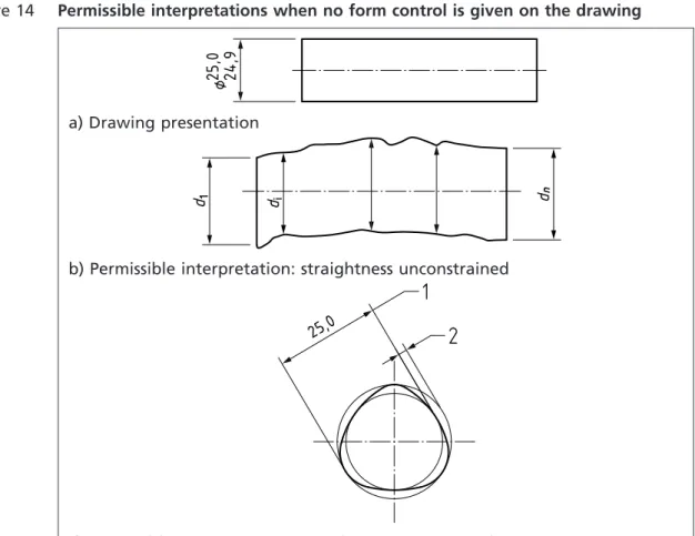
Where no relationship is specified, any geometrical tolerance applied to the feature-of-size applies regardless of feature size, and the two requirements are treated as unrelated (see Figure 14). The limits of size do not control the form, orientation, or the spatial relationship between, individual features-of-size. Consequently, if a particular relationship of:
• size and form; or • size and location; or • size and orientation;
is required, it should be specified.
Limits of size for an individual feature-of-size shall be interpreted according to the principles and rules defined in the following standards.
BS EN ISO 8015:2011Geometrical product specifications (GPS) – Fundamentals – Concepts, principles and rules
BS EN ISO 14405-1 Geometrical product specifications (GPS) – Dimensional tolerancing – Part 1: Linear sizes (ISO 14405-1:2010)
BS EN ISO 14660-1 Geometrical Product Specifications (GPS) – Geometrical features – Part 1: General terms and definitions.
BS EN ISO 14660-2 Geometrical Product Specifications (GPS) – Geometrical features – Part 2: Extracted median line of a cylinder and a cone, extracted median surface, local size of an extracted feature
Figure 14 Permissible interpretations when no form control is given on the drawing
a) Drawing presentation
b) Permissible interpretation: straightness unconstrained
c) Permissible interpretation: roundness unconstrained
NOTE For any cross-section of the cylinder, there is no roundness control.
22.1.2
Limits of size with mutual dependency of size and form
COMMENTARY ON22.1.2Some national standards apply, or have applied, the Envelope Requirement to all features-of-size by default. As the Envelope Requirement has been the default, they have not used a symbol to indicate this requirement; rather they use a note to indicate when this is not required. This system of tolerancing is sometimes described as the Principle of Dependency, or the application of the Taylor Principle.
Standards which apply, or have applied, the Envelope Requirement by default include BS 308 and ASME Y14.5 [1] (the requirement that there is an envelope of perfect form corresponding to the Maximum Material Size of the feature is defined as Rule #1 in ASME Y14.5).
ISO 2768-2 includes an option for marking drawings to indicate that the Envelope Requirement applies to all features of size on the drawing, but this marking is neither widely used nor well understood, and is not recommended. Use of ISO 2762-2 is in any case inadvisable (see9.3).
ISO 14405-1 allows the default interpretation of size requirements to be changed for an TPS. A number of different possibilities are available, including the option of making the Envelope Requirement the default interpretation of size for the entire specification.
If the default interpretation of size is to be changed for a TPS, the following indication shall appear in or near the title block of each drawing:
SIZE ISO 14405
followed by the relevant modifier.