Old Dominion University Old Dominion University
ODU Digital Commons
ODU Digital Commons
Electrical & Computer Engineering Theses &
Disssertations Electrical & Computer Engineering
Summer 8-2020
A Novel Non-Enzymatic Glucose Biofuel Cell with Mobile Glucose
A Novel Non-Enzymatic Glucose Biofuel Cell with Mobile Glucose
Sensing
Sensing
Ankit BainganeOld Dominion University, [email protected]
Follow this and additional works at: https://digitalcommons.odu.edu/ece_etds Part of the Electrical and Computer Engineering Commons
Recommended Citation Recommended Citation
Baingane, Ankit. "A Novel Non-Enzymatic Glucose Biofuel Cell with Mobile Glucose Sensing" (2020). Doctor of Philosophy (PhD), Dissertation, Electrical/Computer Engineering, Old Dominion University, DOI: 10.25777/2xc4-ba54
https://digitalcommons.odu.edu/ece_etds/220
This Dissertation is brought to you for free and open access by the Electrical & Computer Engineering at ODU Digital Commons. It has been accepted for inclusion in Electrical & Computer Engineering Theses & Disssertations by an authorized administrator of ODU Digital Commons. For more information, please contact
A NOVEL NON-ENZYMATIC GLUCOSE BIOFUEL CELL WITH MOBILE
GLUCOSE SENSING
by Ankit Baingane
B.E. August 2016, Nagpur University, India
M.S. December 2017, University of Maryland, Baltimore County
A Dissertation Submitted to the Faculty of Old Dominion University in Partial Fulfillment of the
Requirements for the Degree of
DOCTOR OF PHILOSOPHY
ELECTRICAL AND COMPUTER ENGINEERING OLD DOMINION UNIVERSITY
August 2020
Approved by:
Gymama Slaughter (Director) Chungsheng Xin (Member) Barbara Hargrave (Member) Shirshak Dhali (Member) Nancy Xu (Member)
ABSTRACT
A NOVEL NON-ENZYMATIC GLUCOSE BIOFUEL CELL WITH MOBILE GLUCOSE SENSING
Ankit Baingane
Old Dominion University, 2020 Director: Dr. Gymama Slaughter
Herein, we report a novel non-enzymatic glucose biofuel cell with mobile glucose sensing. We characterized the power generation and biosensing capabilities in presence of glucose analyte. This system was developed using a non-enzymatic glucose biofuel cell consisting of colloidal platinum coated gold microwire (Au-co-Pt) employed as an anode and the cathode which was constructed using a Gas diffusion electrode (GDE) with a platinum catalyst. The non-enzymatic glucose biofuel cell produced a maximum open circuit voltage of 0.54 V and delivered and a maximum short circuit current density of 1.6 mA/cm2 with a peak power density of 0.226 mW/cm2 at a concentration of 1 M glucose. The non-enzymatic glucose biofuel cell produced an open circuit voltage of 0.38 V and delivered and a short circuit current density of 0.225 mA/cm2 with a peak power density of 0.022 mW/cm 2 at a concentration of 5 mM glucose. These findings showed that glucose biofuel cells can be further investigated in the development of a self-powered glucose biosensor. When used as self-powered glucose sensor, the system showed a good sensitivity of 0.616 μA mM−1 and linear dependence with a correlation coefficient of 0.995 in the glucose concentration range of 2 mM to 50 mM.
The system was further characterized by testing the performance of the system at various temperature, pH and amidst various interfering and competing chemical species such as uric acid, ascorbic acid, fructose, maltose and galactose. A charge pump circuit consisting of a blinking LED was connected to the biofuel cell to amplify the input voltage to power small electronic devices. The
blinking frequency of the LED corresponds to the glucose concentration. An android mobile phone camera application was used to measure this LED blinking frequency which was in turn converted into the glucose concentration readings using image processing in MATLAB. The user was notified via text message and an email.
iv
This thesis is dedicated to my parents Ratna and Bhanudas Baingane, my brother Aditya, and all my friends & family.
vi ACKNOWLEDGMENTS
Foremost, I would like to thank my advisor, Dr. Gymama Slaughter, for her patience and guidance throughout the project. She has been a true mentor to me, and I couldn’t have asked for anyone better. Her mentorship was paramount in helping me set long-term career goals. I would also like to thank Dr. Shankar Narayanan, Dr. Meimei Lai, Dr. Thakshila Lingaye, Dr. Faruk Hossain and Dr. Ahmad Qamar for giving me an opportunity to work with them. Their guidance helped me gain a wider breadth of experience during my PhD. I would also like to thank my committee members Dr. Barbara Hargrave, Dr. Nancy Xu, Dr. Chenshung Xin and Dr. Shirshak Dhali for their encouragement and insightful comments. Most importantly, I would like to thank my exceptional family and my girlfriend Madison Rose for their constant support, encouragement and unwavering love that has allowed me to be ambitious and achieve my goals. Lastly, I thank my lab-mate Peyton Miesse and Dominic Nnanyelugoh and my friends Kunal Bendey, Prasad Akmar, Saikat Bainerjee and Kapeel Sable for providing humor and entertainment, but most importantly just being there for me.
TABLE OF CONTENTS Page LIST OF TABLES... ix LIST OF FIGURES ... x Chapter I. INTRODUCTION ... 1 BACKGROUND ... 1 PROBLEM STATEMENT ... 11 DISSERTATION CONTRIBUTION ... 12 SCOPE OF DISSERTATION ... 12
II. BIOFUEL CELL ... 14
FUEL CELL ... 14
BIOFUEL CELL ... 17
III. GLUCOSE BIOSENSOR ... 26
GLUCOSE MONITORING IN BLOOD ... 27
GLUCOSE MONITORING IN ALTERNATIVE PHYSIOLOGICAL FLUIDS ...31
IV. CHARGE PUMP CIRCUIT ... 35
CHARGE PUMP CIRCUIT ... 35
S882Z INTEGRATED CIRCUIT ... 40
V. ELECTROCHEMICAL CHARACTERIZATION ...43
CYCLIC VOLTAMMETRY (CV) ...43
CHRONOAMPEROMETRY (CA) ...47
CURRENT-VOLTAGE CHARACTERISTICS (IV) ... 49
viii
Chapter Page
VI. MATERIALS AND METHODS ... 53
MATERIALS ... 53
ELECTRODE FABRICATION AND DESIGN ... 53
CHARGE PUMP CIRCUIT FABRICATION ... 55
ESP8266, MATLAB AND ANDROID APPLICATION ... 57
VII. RESULTS ... 62
CYCLIC VOLTAMMETRY (CV) ... 64
CURRENT-VOLTAGE CHARACTERISTICS (IV) ... 67
pH AND TEMPERATURE ... 70
CHRONOAMPEROMETRY (CA) ... 71
SELFPOWERED GLUCOSE BIOSENSING ... 75
MATLAB IMAGE PROCESSING FROM ANDROID APPLICATION DATA …….… 77
ESP DATA PROCESSING ... 78
INTERFERENCE STUDY ... 81 VIII. CONCLUSION ... 84 FUTURE WORKS ... 85 REFERENCES ... 87 APPENDIX A ………...……… 103 APPENDIX B ……….…106 VITA ... 110
LIST OF TABLES
Table Page
1. Normal blood glucose levels for non-diabetic and diabetic people……….…. 1 2. Glucose concentration level in different physiological fluids for healthy and diabetic
x LIST OF FIGURES
Figure Page
1. Example of most commonly available methods for individual with diabetes to
monitor and maintain normal blood glucose levels …... 5
2. A continuous glucose monitoring system with implanted sensor and data reader... 6
3. Schematic of a self-powered continuous glucose monitoring system with wireless data access and monitoring. ...11
4. Hydrocarbon Fuel Cell Representation ... 15
5. Biofuel cell schematic showing its major components and basic operation. In this example, the anodic electron transfer occurs through a mediator while at the cathode it occurs directly through a biological catalyst………. 18
6. Schematic representation of Enzymatic biofuel Cell ... 20
7. Schematic reference of power range that some of the alternative energy production methods provide ... 22
8. A model of a non-enzymatic biofuel cell ... 24
9. Conversion of glucose to gluconic acid using glucose oxidase. ... 28
10. Illustration of a glucometer and continuous glucose monitor (CGM) ... 29
11. Schematic of the microneedle glucose-sensing patch on the forearm ... 32
12. A) Flexible glucose sensor. B) Glucose sensor integrated into a wearable wristband for noninvasive sensing in sweat. ... 33
13. Two-step charge discharge cycle. ... 36
14. This reconfiguring of the basic boost-converter charge pump results in a circuit which converts a positive rail to a negative one, which is frequently needed for biasing or providing an offset voltage. ... 38
15. Schematics of charge pump circuit designed in Eagle. ... 41
16. Internal operation of charge pump IC. ... 42
17. CV excitation signal showing a a typical reduction occurring from (a) to (d) and an oxidation occurring from (d) to (g)………... 44
18. Voltammogram of a Single electron oxidation-reduction. ... 45
19. Resistor i-v characteristic curve. ... 50
20. Fabricated Au-co-Pt anode on left and GDE cathode on the right. ... 54
21. Sawtooth frequency obtained from charge pump circuit. ... 56
Figure Page 23. Sample code for ESP8266 programming which takes the analog values coming from
charge pump and plots it versus time. ... 59 24. Assembled biofuel cell setup with voltage measurement. ... 62 25. Scanning electron microscopy (SEM) images of (A) Braided Au microwire,
(B) high-resolution SEM image of Au-co-Pt abiotic anode and (C) Au-co-Pt abiotic anode ...63 26. Cyclic voltammetry performed on the Au-co-Pt showing linear increase in current with
increase in glucose concentration. ... 64 27. Internal layers of GDE electrode...65 28. Cyclic voltammetry performed on the GDE cathode showing linear increase in current with
increase in purged oxygen. ... 66 29. Polarization curve obtained from the non-enzymatic biofuel cell from glucose concentration
of 1mM to 1M. ... 67 30. Power curve obtained from the non-enzymatic biofuel cell from glucose concentration of
1mM to 1M. ... 68 31. Power-concentration curve from 1mM to 50mM glucose ...69 32. Effect of pH on the frequency of the non-enzymatic glucose biosensing system operating
in 5 mM glucose at 37 o C. ... 70 33. Effect of temperature on the frequency of the non-enzymatic glucose biosensing system
operating on 5 mM glucose at a pH of 7.4... 70 34. Amperometry response of the Au-co-Pt electrode to successive addition of 2 mM
glucose in 0.1 M PBS solution after every 50 seconds interval. ... 71 35. Calibration curve derived from the linear response of the sensor to change in glucose
concentration. ... 72 36. IC circuit with glucose biofuel cell as power source ... 73 37. The construction of the self-powered glucose biosensor via a charge pump integrated
circuit and a capacitor functioning as a transducer. ... 74 38. Charge pump circuit with LED blinking. ... 75 39. A model of a novel self-powered glucose monitoring biosystem with data acquisition
using mobile camera. ... 76 40. Received text message and email by the user containing information about their
blood glucose level. ...77 41. A model of miniaturized continuous glucose monitoring system with remote access
xii
Figure Page
42. Capacitor charge/discharge rate obtained from glucose biosensing system operating in the absence (blue curve) and in the presence of 5 mM glucose (black curve) using the
e-oscilloscope program……... 79
43. Adafruit live feed of the capacitor charge/discharge rate obtained from glucose biosensing system operating in the presence of 5 mM glucose using the e-oscilloscope program... 80
44. Calibration curve of hybrid glucose biosensing system operating in various glucose concentration using the e-oscilloscope. ... 80
45. The charge/discharge frequency of the capacitor in the presence of 5 mM glucose and 0.3 mM interfering species ... 82
46. The charge/discharge frequency of the capacitor in the presence of the respective interfering analyte independent of glucose ... 83
47. Stability study performed for 20 days at 10 mM glucose concentration. ………... 84
48. Ideal charge pump circuit ……… 103
49. Output voltage obtained across different load resistances of 1, 10 and 100 K Ohms …………. 104
50. Output waveforms obtained at different nodes and stages ……… 105
51. Power curve obtained from MATLAB simulation ………. 107
52. Polarization curve obtained from the MATLAB simulation ………. 108
CHAPTER 1
INTRODUCTION
Background
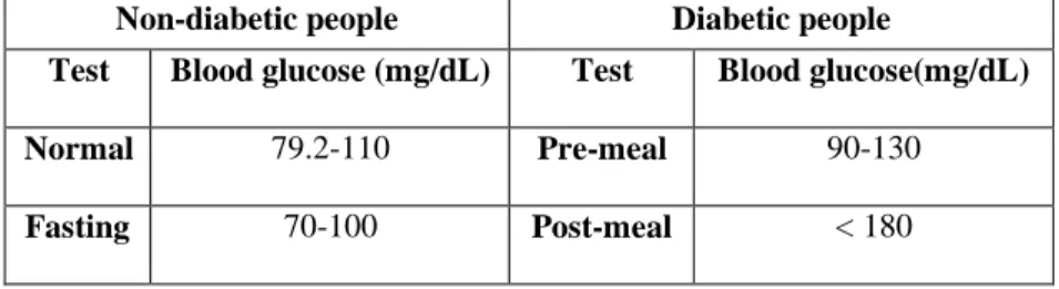
Blood glucose is the main type of sugar found in the blood and is the main source of energy. Glucose comes from the food that an individual eats and is also made in the liver and muscles. Blood carries glucose to all the body’s cells to use for energy. The pancreas - an organ, located between the stomach and spine, helps with digestion and releases a hormone called insulin into the blood [1]. Insulin helps the blood carry glucose to all the body’s cells. Sometimes an individual’s body does not make enough insulin, or the insulin does not work the way it should [2,3]. Glucose then stays in the blood and does not reach the cells. If blood glucose levels get too high, it can cause the disease, diabetes, or prediabetes. Over time, having too much glucose in the blood can cause health problems. Table I represents normal levels of blood glucose for non-diabetic and diabetic individuals.
Table I. Normal blood glucose levels for non-diabetic and diabetic people Non-diabetic people Diabetic people
Test Blood glucose (mg/dL) Test Blood glucose(mg/dL) Normal 79.2-110 Pre-meal 90-130
Fasting 70-100 Post-meal < 180
Prediabetes is when the amount of glucose in the blood is above normal yet not high enough to be called diabetes [3]. With prediabetes, the chances of getting type 2 diabetes, heart disease, and
2 stroke are higher. With some weight loss and moderate physical activity, an individual can delay or prevent type 2 diabetes. The typical signs and symptoms of diabetes are:
● being very thirsty ● urinating often ● feeling very hungry ● feeling very tired
● losing weight without trying ● sores that heal slowly ● dry, itchy skin
● feelings of pins and needles in your feet ● losing feeling in your feet
● blurry eyesight
However, some people with diabetes do not have any of these signs or symptoms. There are three main types of diabetes: type 1, type 2, and gestational diabetes. People can develop diabetes at any age.
Type 1 diabetes
Type 1 diabetes, which used to be called juvenile diabetes, develops most often in young people; however, type 1 diabetes can also develop in adults [1,2]. In type 1 diabetes, the body no longer makes insulin or enough insulin because the body’s immune system, which normally protects the body from infection by getting rid of bacteria, viruses, and other harmful substances, has attacked and destroyed the beta cells that make insulin [3]. This type of diabetes is less common and mostly diagnosed in young adults and children and accounts for 5% of the total diabetes cases [1,3]. Treatment for type 1 diabetes includes:
● sometimes taking medicines by mouth ● making healthy food choices
● being physically active
● controlling blood pressure levels ● controlling cholesterol levels Type 2 diabetes
Type 2 diabetes also known as adult-onset diabetes, can affect people at any age, even children. However, type 2 diabetes develops most often in middle aged and older people [1,2,3,4,5]. People who are overweight and inactive are also more likely to develop type 2 diabetes. Type 2 diabetes usually begins with insulin resistance - a condition that occurs when fat, muscle, and liver cells do not use insulin to carry glucose into the body’s cells to use for energy. As a result, the body needs more insulin to help glucose enter cells. At first, the pancreas keeps up with the added demand by making more insulin. Over time, the pancreas does not make enough insulin when blood sugar levels increase, such as after meals. If the pancreas can no longer make enough insulin, the individual will need to get treated for type 2 diabetes. Type 2 is the most common form of diabetes accounting for 90 – 95% of the total diabetes cases [1]. Treatment for type 2 diabetes includes:
● using medication
● making healthy food choices ● being physically active
● controlling blood pressure levels ● controlling cholesterol levels Gestational diabetes
Gestational diabetes can develop when a woman is pregnant. Pregnant women make hormones that can lead to insulin resistance [3,4,5]. All women have insulin resistance late in their
4 pregnancy. If the pancreas does not make enough insulin during pregnancy, a woman develops gestational diabetes. Overweight or obese women have a higher chance of gestational diabetes. Also, gaining too much weight during pregnancy may increase your likelihood of developing gestational diabetes. Gestational diabetes usually goes away after the baby is born. However, a woman who has had gestational diabetes is more likely to develop type 2 diabetes later in life. Babies born to mothers who had gestational diabetes are also more likely to develop obesity and type 2 diabetes. The prevalence of gestational diabetes was as high as 9.2% according to CDC report from 2014 [6]. Other diabetes
Other forms of diabetes include congenital diabetes, cystic fibrosis-related diabetes, steroid diabetes, and several forms of monogenic diabetes are also common. Congenital diabetes is a result of genetic defects of insulin secretion and steroid diabetes is induced by high doses of glucocorticoids. These other types of diabetes accounts for 1 – 5% of the total diabetes cases [4,5,6]. According to a 2014 report, from the Centers for Disease Control (CDC), 29.1 million people or 9.3% of the population suffer from diabetes in the United States (US) alone, and the cost incurred to keep diabetes under control was 245 billion US dollars [6]. Over time, diabetes can lead to serious problems with blood vessels, the heart, nerves, kidneys, the mouth, eyes, and feet. These problems can lead to an amputation of a limb. The most serious problem caused by diabetes is heart disease. When a person has diabetes, they are more than twice as likely as people without diabetes to have heart disease or a stroke. With diabetes, the person may not have the usual signs or symptoms of a heart attack.
Continuously checking and recording blood glucose levels can help monitor and better manage diabetes. If the blood has too much or too little glucose, the person may need a change in diet, physical activity, or medication to have a stress-free and healthy lifestyle.
The most commonly available methods for an individual with diabetes to monitor and maintain normal blood glucose levels are:
• Finger prick test using a test strip and a glucometer
• Continuous glucose monitoring (CGM) system
The finger prick test involves pricking the finger using a lancet and extracting the blood drop with a disposable glucose test strip, which is then placed in the glucometer to measure the blood glucose level as shown in Figure 1.
Figure 1. Example of most commonly available methods for individual with diabetes to monitor and maintain normal blood glucose levels [8]
The disposable test strip consists of a glucose selective enzyme such as glucose oxidase. The glucose selective enzyme oxidizes the glucose in the blood to produce gluconic acid and release electrons. These released electrons are proportional to the glucose concentration, which is converted into variable voltages using analog to digital converters. The meter then displays the level in the units of mg/dl or mmol/l. The test strips used in glucometer are expensive. The consumer cost for each glucose strip ranged from about $0.35 to $1.00. Manufacturers often provide meters at little to no
6
cost to create a demand for the use of the profitable test strips. Individuals with type 1 diabetes may test as often as 4 to 10 times a day due to the dynamics of insulin adjustment, whereas with type 2 typically, tests are less frequent, especially when insulin is not part of treatment [7,8]. These strips are also affected by external factors like humidity, temperature, and altitude. For different batches of the test strips, the glucometer requires recalibration. Additionally, the blood glucose reading can drift by as large as 4 mmol/dL or 72 mg/dL which can prove to be fatal in blood glucose monitoring [7,8,9]. Therefore, close monitoring of blood glucose levels may involve pricking the finger multiple times a day, which may prove painful and tedious.
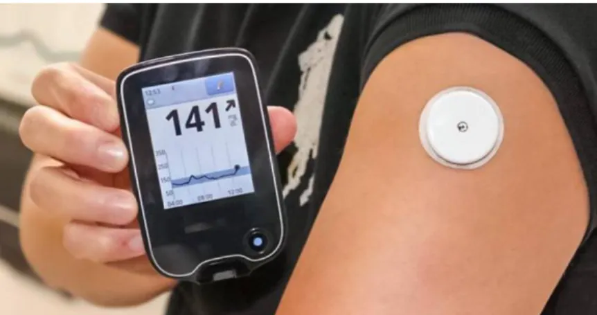
To reduce finger pricking frequency, continuous glucose monitoring systems (CGMs) were developed. A continuous glucose monitoring system (CGM) can consist of a disposable sensor placed under the skin, a transmitter connected to the sensor and a reader that receives and displays the measurements [10,11,12] as shown in Figure 2.
Figure 2. A continuous glucose monitoring system with implanted sensor and data reader. [12]
The sensor can be used for several days before it needs to be replaced [11-13]. The devices provide real-time measurements and reduce the need for finger prick testing. A drawback is that the meters are not as accurate because they read the glucose levels in the interstitial fluid which lags the
levels in the blood. Also, CGMs are powered by an external power source such as a battery, thereby rendering the device bulky. CGM devices often requires recalibration every 12 hours after the first day.
A lot of research has been conducted to improve the quality and efficiency of CGMs. Companies like Medtronic and Dexcom are at the forefront of glucose monitoring research as it is a very valuable market for them, but the CGM devices developed by both Medtronic and Dexcom, have a bulky receiver, often making them cumbersome to carry. This is mainly because these systems are powered by external power sources such as batteries and are very difficult to miniaturize. Also, one must calibrate the receiver for accurate blood glucose measurements which takes nearly 2 hours and demonstrates a maximum lifetime of just one week [11-13]. Although these devices show promising results, the quest to maintain normal blood glucose levels and improving quality of life for individuals with diabetes remains a challenge. It is imperative that there is a closed loop system that would be minimally invasive, flexible, and easy to use and where the data is easily accessible to the end user and service providers. To solve this problem, a lot of research has been done on making these monitoring devices as non-invasive and small as possible and the development of miniaturized alternative power sources to batteries.
Whenever a need for small and portable power source arises, alternative fuel sources other than batteries are needed. Alternative fuel source offers flexibility when energy needs cannot be met by traditional means due to location, emergency power loss and lack of space. The market for rechargeable batteries is projected to grow at a rate of 7% per year through 2027 [14]. Despite their many advantages, batteries are hindered by the limited lifetime of the materials used to construct the battery. In addition, many batteries use hazardous chemicals that can potentially leak, can cause poisoning if not disposed of properly or even explode [15]. Also, batteries are limited by size as they cannot be miniaturized after a certain point due to limitations in achieved power densities. Therefore,
8 there is a high demand for alternate power sources that can compete with current battery technologies.
The first conventional fuel cell was introduced by Neidrach and Grubb from General Electric for NASA [16]. The fuel cell consisted of platinum as a noble metal electrocatalyst, which oxidizes hydrogen and reduces oxygen. Oxidation of hydrogen produces protons and electrons which moved through the electrolyte and then the external circuit. This flow of electrons in the system results in the generation of electricity. Oxygen is reduced at the cathode when the electron in the system recombines with the oxygen present in the system. This reaction produce water as a byproduct. A platinum metal catalyst is used because of its efficiency for oxidizing hydrogen. However, in large-scale applications, the use of platinum in fuel cells is limited due to its expensive and nonrenewable nature. In addition, hydrogen fuel is susceptible to carbon contamination and a continuous supply of hydrogen fuel is needed to generate electrical power continuously. These complicate the oxidation process due to carbon monoxide poisoning of the electrocatalyst. The high cost of noble metal electrocatalyst, carbon monoxide poisoning and need for continuous supply of hydrogen results in the unsustainability of hydrogen fuel cells as an ideal power source for implantable bioelectronic devices. The glucose biofuel cell has been looked upon as an alternative to powering implantable bioelectronic devices.
The main motivation for the extensive research in the field of glucose biofuel cell technology is attributed to the search for an alternative sustainable fuel source that is cost-effective and can meet increasing global energy demands and recent advancements in microelectronics [17]. Many researchers are working to use glucose biofuel cells in powering implantable bioelectronic devices. Conventional fuel cell assembly consists of an anode, a cathode and an electrolyte and relies on the conversion of the chemical energy into electrical energy. In a fuel cell, mainly two types of reactions occur: 1) oxidation and 2) reduction reaction. The complete reaction is called a redox reaction. The
oxidation reaction occurs at the anode, and the reduction reaction occurs at the cathode. When the fuel is oxidized due to the redox reaction, electrons are released in the electrolyte, which then travels through an external circuit to the cathode producing electricity. In traditional batteries, two or more solid reactants undergo a chemical reaction which converts chemical energy into electrical energy by consuming one of the reactants. When the disposable reactant is completely consumed, the battery cannot produce any more electrical energy. Once the battery is discharged i.e., the reactant is completely consumed, the battery either must be recharged in case of rechargeable batteries or replaced (traditional batteries). In the case of a glucose fuel cell, the electrical energy is produced due to the chemical reaction occurring between liquid and/or gaseous reactants as long as there is a continuous supply of glucose and the enzymes remain active, in the case of an enzymatic biofuel cell. Glucose is a simple sugar which is mainly produced by plants and algae using water and carbon dioxide from the atmosphere in the presence of sunlight. During this reaction, oxygen is produced as a byproduct and released in the atmosphere. Along with carbon dioxide and sunlight, the reaction also involves Adenosine Triphosphate (ATP) and Nicotinamide Adenine Dinucleotide Phosphate (NADPH) [18]. Scientists have found that this produced glucose can be used as a fuel in glucose biofuel cells since one molecule of glucose upon complete oxidation to CO2, generates 24 electrons to produce electrical energy. This glucose fuel is then oxidized into gluconolactone in the presence of oxygen, releasing electrons which in turn reduces the oxygen to produce electricity. Glucose biofuel cell can be differentiated from any other electrochemical energy sources based on the anodic catalysts used for the oxidation of the fuel. A major advantage of glucose biofuel cells over conventional fuel cells is that it employs cheap and environmentally friendly fuel and materials. This makes glucose biofuel cells a great alternative to conventional fuel cells. Also, glucose biofuel cells have high conversion efficiency at ambient temperatures and pH conditions. This electrical energy produced by glucose biofuel cells can be potentially used to power small bioelectronic devices like
10 pacemakers and continuous glucose monitors. Therefore, great interest has been shown in the field of developing a highly efficient glucose biofuel cell that can generate large amount of electrical energy to power small devices. These glucose biofuel cells can also be employed as a self-powered glucose biosensing system with the addition of a sensing circuit.
As mentioned above, diabetes is one of the most common and debilitating diseases in the world, and it happens due to increased levels of glucose in the blood. Elevated concentrations of glucose in the body are considered one of the important parameters that represent the different states of disorder [19,20]. Continuous glucose monitoring is the best way to minimize the complications arising from increased glucose levels in the body. Implantable glucose biosensors that have 3 electrochemical sensors have continued to attract significant attention because of their unique advantages, such as ease of fabrication, rapid response time, low limit of detection, high selectivity, and sensitivity [20-21, 25]. Electrochemical sensors can convert chemical or biological information rapidly, ranging from the concentration of a specific analyte to the total composition analysis, into an electrical signal [22-24].
Most of the biosensors aimed at detection of various analytes consist of an array of electrodes immobilized with enzymes, aptamers, or antibodies [20,23]. It has been observed that, the enzymes denature after some time of continuous use and their performance is widely affected by the surrounding pH and temperature. Also, the enzyme immobilization process must be performed in a controlled environment. To improve on these limitations, materials like carbon nanotubes [20,21], metal oxides [22,23], nano-structured conducting polymers [24-26], graphene [27], etc., have been considered as an alternative. Moreover, interest has been shown in the utilization of noble metals such as gold, platinum, and silver nanoparticles/ nano features in general because of their unique electrochemical properties [28,30]. These nanoparticles improve the direct electron transfer, signal transduction, and efficiency of the sensor. Platinum nanoparticles have been shown to have the
capacity to directly electro-oxidize glucose even in the absence of enzymes and mediators [30]. The large surface area and good biocompatibility of nanoparticles makes nanoparticles and nanocomposites attractive for the construction of biosensor [30,31].
Gas diffusion electrodes (GDE) are electrodes with a conjunction of a solid, liquid and gaseous interface, and an electrical conducting catalyst supporting an electrochemical reaction between the liquid and the gaseous phase [38-42]. GDEs are typically used in fuel cells, where oxygen and hydrogen react at the gas diffusion electrodes, to form water, while converting the chemical energy into electrical energy. Usually the GDEs are porous and the catalyst is fixed in a porous foil, so that the liquid and the gas can interact. Besides these characteristics, the gas diffusion electrode must, of course, offer optimal electric conductivity, in order to enable electron transport with low ohmic resistance [33-36].
Problem statement
The goal of this work is to develop a self-powered continuous glucose monitoring system with wireless data access and monitoring capabilities. The developed system will not need a battery and will work under physiological conditions. The system is designed to exhibit high sensitivity and selectivity towards glucose analyte and have a wide linear range. It is also able to act as a power source for small electronic devices if the need arises. The data obtained can be forwarded to doctors or health care providers, so that they can have a detailed record of the user’s health and act when any kind of anomalies are observed. The fabricated system is equipped with a wireless data access and monitoring system.
12
Figure 3. Schematic of a self-powered continuous glucose monitoring system with wireless data access and monitoring
Dissertation contribution
In this dissertation, we developed a novel non-enzymatic glucose biofuel cell consisting of an anode made up of gold microwire electrodeposited with colloidal platinum and a cathode made up of a platinum catalyst layer on carbon cloth GDE substrate. The power output of the biofuel cell is directly proportional to the glucose concentration level. This biofuel can then be used to power a small charge pump circuit. The charge pump circuit consists of a blinking LED whose blinking frequency is directly proportional to the power produced by a biofuel cell. By incorporating the charge pump circuit, a complete glucose biosensing system was realized. An android application was developed, which uses a mobile camera to measure the blinking frequency using image processing in MATLAB and converts it into glucose concentration. Then a text message is sent to the user containing their body glucose level.
We also performed cyclic voltammetry characterization of the non-enzymatic biofuel cell in the absence and presence of glucose and purged oxygen. Current-Voltage characteristics (IV) tests were carried out to study the power characteristics of the glucose biofuel cell. The performance of
the glucose biofuel cell was verified at different pH and temperature conditions to find the optimal working conditions for the glucose biofuel cell along with interference characterization. Amperometry was also carried out to further study the performance of the biosensor.
Scope of dissertation
The purpose of chapter 2 is to provide background to the thesis and introduce the reader to the electrical and bioelectrical concepts that govern the workings of a basic fuel cell and biofuel cells. The chapter also sheds light on the types of electron transfer methods used in biofuel cells, which constitutes how current flow in a biosensing system occurs.
Chapter 3 focuses on the glucose biosensor in general. This chapter sheds a light on different types and generations of glucose biosensors. It also explains continuous glucose monitoring systems and the current trends in research and development.
Chapter 4 focuses on the charge pump circuit and its operating principle. This chapter provides a detailed explanation of the S882Z charge pump IC and general operation.
Chapter 5 focuses on the different electrochemical characterization methods used.
Chapter 6 focuses on the discussion of the fabricated non-enzymatic glucose biosensing system. The manufacturing methods, materials used in the preparation of the bioelectrodes and charge pump circuit are explained. It also reviews the ESP8266 microcontroller, MATLAB and the developed android application.
Chapter 7 describes all the experimental data, the characterization methods, interference studies and results obtained by the self-powered glucose monitoring system.
Chapter 8 summarizes the studies performed. The result and path forward of the novel glucose biosensing system are also discussed.
14
CHAPTER 2
BIOFUEL CELL
Fuel cell
Fuel cells are electrochemical devices that convert chemical energy in fuels into electrical energy, thereby promising power generation with high efficiency and low environmental impact [43]. Because the intermediate steps of producing heat and mechanical work of most conventional power generation methods are avoided, fuel cells are not limited by thermodynamic limitations of heat engines such as the Carnot efficiency. In addition, because combustion is avoided, fuel cells produce power with minimal pollutants. However, unlike batteries the reductant and oxidant in fuel cells must be continuously replenished to allow continuous operation. Fuel cells bear significant resemblance to electrolyzers [43,44]. In fact, some fuel cells operate in reverse as electrolyzers, yielding a reversible fuel cell that can be used for energy storage. Though fuel cells could, in principle, process a wide variety of fuels and oxidants, of most interest today are those fuel cells that use common fuels (or their derivatives) or hydrogen as a reductant, and ambient air as the oxidant. A hydrocarbon fuel cell is illustrated in 4. This system is characterized by a non-polluting and silent technology.
Figure 4. Hydrocarbon Fuel Cell Representation
In general, traditional fuel cells use noble metal catalysts to generate electrons from fuel oxidation (typical fuels are hydrogen or small organic molecules such as methanol, ethanol, etc.). After the oxidation step, an external circuit transfers the electrons to the cathode side where the electrons react with an oxidant molecule (usually oxygen) and generate electrical work as well as water and heat.
Fuel cells can vary from tiny devices producing only a few watts of electricity, right up to large power plants producing megawatts of power. All fuel cells are based around a central design using two electrodes separated by a solid or liquid electrolyte that carries electrically charged particles between them [43]. A catalyst is often used to speed up the reactions at the electrodes. Fuel cell types are generally classified according to the nature of the electrolyte they use. Each type requires materials and fuels that are suitable for different applications [44].
Basic Fuel cells can be differentiated into various types, depending on the type of electrolyte and operation temperature. Proton exchange membrane fuel cells (PEMFC), Direct methanol fuel
16 cells (DMFC), Phosphoric acid fuel cells (PAFC), Alkaline fuel cells (AFC) and Solid oxide fuel cells (SOFC) are some of the main types of fuel cells produced [45]. Fuel cell technology offers considerable advantages over other processes, such as high conversion efficiency and generation of substantial power density. Although fuel cells yield good results, some factors limit their large-scale application: high cost and future scarcity of noble metal catalysts (e.g., platinum) employed as a base catalyst in many fuel cell devices, issues regarding electrode passivation, and inability to oxidize some of the byproducts generated.Furthermore, hydrogen production, purification, and storage also pose major technical challenges.
In laboratory and commercial settings, acids, alcohol, oxides and hydrogen are used as the fuel source. In the case of portable and implantable electronics, the fuel needs to be readily available inside human body. A standard fuel cell cannot be applied in this situation. To solve this problem, biofuel cells (BFCs) can be looked upon as the ideal power source for portable and implantable electronics. On average there is >100 W of power contained as chemical energy in human body. Biofuel cells transform chemical energy into electrical energy from molecules presents in a living organism. The difference between biofuel cells and batteries is that in BFCs the concentration of the reactants is continually re-established by the body fluids. The constant presence and availability of the fuel directly from the body makes external recharging mechanisms or replacement unnecessary and provides a theoretical capability for operating indefinitely, as long as there is a constant supply of fuel.
Biofuel cell
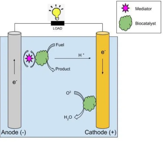
Biofuel cells are structurally and functionally similar to conventional fuel cells as seen in Figure 5, but their catalysts are biological entities such as enzymes, microbes, and organelles [46]. Biofuel cells can be abiotic, enzymatic, microbial, or mammalian type depending on the catalysts used for the oxidation and reduction reactions. The development and fabrication of biofuel cells depend on multidisciplinary research that requires conceptual understanding of the metabolic pathways of microorganisms, catalysts, material sciences, fabrication, and bioelectronics [47,48]. Presently, researchers are focusing on the development of biofuel cells that can be implanted in living organisms to power medical devices and biosensors. Moreover, biofuel cells can also be a better alternative to batteries and conventional fuel cells.
Using biological catalysts gives biofuel cells some unique properties: room temperature operation, catalyst-fuel specificity, membrane-less (no separation between the anode and cathode), and finally, there are a wide range of possible fuels owing to the multitude of biological catalysts that can be used. Biofuel cell fuels (commonly referred to as substrates) include alcohols, sugars, wastewater, and biological fluids such as blood, sweat, and tears. The abundance and sustainable nature of these fuels make biofuel cells a renewable energy option, although it has recently been shown that biofuel cells can even operate using JP-8 aircraft fuel [48]. The choice of electrodes and biocatalysts are the main factors that affect the power generation of a biofuel cell.
18
Figure 5. Biofuel cell schematic showing its major components and basic operation. In this example, the anodic electron transfer occurs through a mediator while at the cathode it occurs directly through a biological catalyst.
Enzymatic biofuel cells consist of enzyme catalysts that have been isolated from a biological source and placed on either the anode, cathode, or both electrodes. Because the enzymes have been removed from their natural environment, they can communicate with mediators or electrodes directly, so they typically have higher power density than microbial or organelle biofuel cells. However, removing the enzymes from their native environment also lowers their stability [49]. Microbial biofuel cells, on the other hand, employ microbial catalysts that are grown directly on the electrodes and remain intact during operation. This greatly increases catalyst lifetime [50,51] but insulates enzymatic reaction sites, making electron transfer to the electrodes more difficult. Regarding the third type of biofuel cell
utilizing organelles, they are in their infancy compared to their enzymatic and microbial counterparts. As a result, they have neither the power output of enzymatic biofuel cells nor the stability of microbial biofuel cells. Organelles, such as mitochondria, can be isolated from living cells and immobilized directly on an electrode [52]. Mitochondria contain a series of membrane-bound enzymes that form an electron transport chain that can communicate directly with an electrode. Because the enzymes are membrane-bound, they are theoretically more stable than those found in an enzymatic biofuel cell, and because the mitochondria are not surrounded by cellular walls, they should be capable of faster electron transfer than a microbial fuel cell. There is a wealth of research for each of these biofuel cell classes, but the focus from this point forward will be on enzymatic biofuel cells.
In enzymatic biofuel cell (EBFC), isolated enzymes are used for oxidation and reduction reactions at the anode and cathode, respectively [53-56]. The interest in EBFCs has increased due to implantable medical devices and biosensors for physiological substances. Besides the health-care applications, enzyme-based biofuel cells have also been used to power various portable and low-power devices. Because of their specificity and selectivity, enzymes are preferred biocatalysts where mixed fuel or reactants are to be used. Practically, the lifetime of EBFCs is limited and researchers have focused on different possible solutions for long-term operational stability of EBFCs. These possibilities include enzyme immobilization, genetic engineering of enzymes, and process development to replenish the enzyme level at the electrodes. The operation of an EBFC resembles the functioning of a conventional fuel cell [54,55]. A biofuel cell generates electricity from carbohydrates (sugar) utilizing enzymes as the catalysts through the principles of power generation present in living organisms. The EBFC incorporates an anode consisting of carbohydrate-digesting enzymes and a mediator and a cathode comprising oxygen-reducing enzymes and a mediator on either side of a separator membrane. The anode extracts electrons and hydrogen ions from the sugar (glucose) through enzymatic oxidation. At the cathode, the hydrogen ions and electrons combine with oxygen and produce water as seen in Figure 6.
20
Figure 6. Schematic representation of enzymatic biofuel cell.
Due to the selective reactivity of the enzymes at each electrode, no cross-reaction occurs between the anode and the cathode. In general, the EBFC could be classified into many types based on fuel containment, fuel and catalyst sources, origin of the catalytic enzymes, and method of electron transfer between the reaction site and the electrode [55,56]. Similarly, the enzymes generally used in biofuel cells can also be divided into three groups depending on the location of the enzyme active centers and type of electron transfer between the enzyme and the electrode. These groups are:
(1) enzymes having nicotinamide adenine dinucleotide (NADH/NAD+) or nicotinamide adenine
dinucleotide phosphate (NADPH/NADP+) redox centers (these redox centers are weakly bound to the enzyme protein),
(2) enzymes having redox centers at near surface or peripheral locations, and
deep in the protein or glycoprotein shell.
The enzymes described in points (1) and (2) carry out DET between the electrode surface and enzyme active centers, while enzymes in group (3) are not able to perform the DET with the electrode surface. Therefore, electron transfer to the electrode surface can be achieved by the use of electron transfer mediators. These mediator molecules (either electron donor or acceptor) can be accepted by the redox enzymes used in biofuel cells, and therefore, MET-based EBFCs were focused on by different research groups worldwide [56].
An oxidoreductase enzyme can oxidize carbohydrates, alcohols, lactate, or even amino acids, and transfer electrons from the fuel to the electrode surface. Depending on the fuels mentioned above, it is possible to prepare anode-based electrodes by immobilizing different types of enzymes. For sure, glucose oxidase has been the most often employed enzyme since the first description of a biofuel cell. Its in vivo application is desirable because of different human physiological fluids, such as blood, plasma, saliva, and tears, that contain sugar (glucose). Scientists are also testing other enzymes, depending on the target fuel. As for enzyme-based cathodes, laccase or bilirubin oxidase usually perform the oxygen reduction reaction.
The difference between the thermodynamic potential of the cathode and the anode (ΔEc-Ea) expresses the cell voltage, but this value can decrease by several orders of magnitude due to overvoltage (Δη). Δη results from (i) slow electron transfer occurring at both electrode sides; (ii) ohmic drop (∑Ω), associated with all the resistances in the system (film diffusion, membrane, supporting electrolyte); and (iii) electrode wear out (Δ£), a parameter that reflects electrode degradation described in Equation 1:
E
cell= Δ
Ec-Ea- Δη - ΣΩ - Δ£ (1)
This provides important information that can be applied to any enzymatic electrode. Maximizing the so-called thermodynamic potential window (Ec - Ea) yields better biofuel cell
22 performance [57]. Therefore, enzymatic biofuel cell researchers aim to prepare/achieve bioelectrodes that facilitate the catalyzed reactions, to increase the open cell voltage (OCV). Moreover, these researchers target better cell design and prototypes that can reduce the overall resistances, making the electric current flow more easily through the system. To produce commercial devices, it is also necessary to keep Δ£ as low as possible.
Another crucial parameter associated with the performance of any fuel cell is the power density that this system provides. This parameter reflects the electron generation rate in the enzyme-catalyzed reactions. Unlike traditional fuel cells, which afford power densities of the order of milli to kilowatts, enzymatic biofuel cells generate power densities in the order of micro to a few milliwatts, which is sufficient for applications in portable low-powered electronic devices. The representative scheme in Figure 7 shows the power range of some of the alternative methods of energy production [58].
Figure 7. Schematic reference of power range that some of the alternative energy production methods provide
Despite the various advantages and possible applications of enzymatic biofuel cells, to achieve an efficient practical device, it is necessary to consider some crucial factors when developing this type of system. The first major challenge is the fact that enzymes are proteins; therefore, these biomolecules display a weak three-dimensional structure that must be maintained to ensure that its catalytic activity is retained. Although enzymes are highly specific and efficient catalysts, they have a limited lifetime in solution. Hence, their use in biofuel cells requires a critical step: immobilizing the enzyme onto an electrode surface. Achieving electrical contact between the enzyme and the electrode is also fundamental because this is one of the most important processes in the field of bioelectrochemistry. Achieving a high electron transfer rate from the active site of an immobilized enzyme to the electrode surface is probably the most critical point when constructing an enzymatic biofuel cell. Most research analyzing glucose in blood or serum focuses on enzymatic amperometric sensors owing to their simple design and performance. Amperometric enzyme biosensors rely on the measurement of current on the application of a potential between working and reference electrodes. The magnitude of this current depends on the concentration of a redox-active reagent or product in an enzymatic reaction.
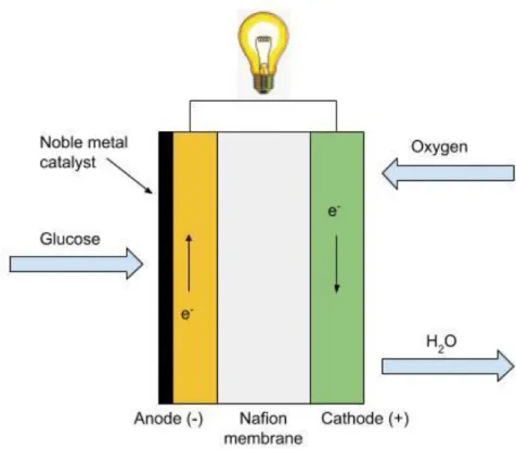
Amperometric enzymes based glucose biosensors suffer from complex and complicated enzyme immobilization strategies, critical operating conditions (temperature and pH), high cost and instability of the enzyme over a long period of time [59]. The activity of enzymes is very largely affected by the temperature, pH, humidity, and the presence of toxic chemicals [60]. To address these limitations, enzyme-free sensors, as seen in Figure 8, have been investigated to improve the electrocatalytic activity and selectivity toward the oxidation of glucose. Non-enzymatic biofuel cells use abiotic catalysts like platinum or other noble metals to carry out the electrooxidation of biofuel. Inert metals (Pt, Au, and Ni) metal alloys containing Pt, Au, Pb, Ir, Ru, Cu, and Pd and metal-dispersed carbon nanotubes (CNTs) frameworks in which Pt, Pb, Pd, or Au are mixed with CNTs to form nanocomposites have been explored for glucose catalysis [59,60].
24
Figure 8. A model of a non-enzymatic biofuel cell
An abiotic glucose fuel cell converts the chemical energy of glucose and oxygen into electric power using noble metals as the catalysts. The general electrode reactions of an abiotic biofuel cell involve oxidation of glucose to gluconic acid at a platinum-based anode catalyst, and oxygen is reduced to water at the cathode. Released protons travel from the anode to the cathode through a proton-conducting membrane or electrolyte and generate electric power. The biofuel may be glucose, methanol, and ethanol [59]. Glucose is used more commonly as biofuel. Though in recent decades much attention has been paid to enzymatic, microbial, and whole cell/organism-based bio-fuel cells for implantable devices, abiotic biofuel cells also possess some advantages over biotic biofuel cells. Though the use of noble catalysts results in a more expensive biofuel cell system, abiotic biofuel cells promise tolerance to high temperatures during steam sterilization or a wide range of pH values. An abiotic cells also promise for long-term stability at operative and physiological conditions. Moreover, abiotic biofuel cells may also perform better at physiological concentrations of glucose [60]. Abiotic glucose fuel cell exhibits
higher stability and a longer life span as compared to EBFC.
Due to increasing research and development in the field of biofuel cells, abiotic fuel cells can be seen as an alternative to sconventional fuel cells based on metal catalysts. These devices constitute a system that can directly transform chemical energy into electricity through reactions involving biochemical steps, or even a system in which the activity of the cell (or part of it) stems from the action of biocatalysts. The connection between biology and electricity and the concept of a biofuel cell have been known since 1911, when MC Potter noted that a culture of the bacterium E. coli produced electricity in half-cell studies employing platinum electrodes [61]. During the height of the Space race, the interest in this technology increased. The United States space program decided to use the biofuel cell in two entirely different ways. The first was to treat the waste originating from the spacecraft, and the second was to obtain electricity from the treated waste using the reactions involving the biofuel cell. Motivated by the possible in vivo application of this device, Yahiro et al. were the first to describe a biofuel cell that used isolated enzymes on the surface of an electrode and to show that it was possible to produce electricity using the enzyme glucose oxidase (GOx) [62]. The main advantages of the biological fuel cells are as follows:
1. The use of clean and renewable catalysts (enzymes or microorganisms),
2.
The ability to operate at mild temperatures (20-40 °C) and physiological pH conditions,3. The possibility to use several fuels because enzymes and microorganisms offer diversity and specificity,
4. Scaling up the use of biocatalysts tends to reduce production costs, which is not possible for non-renewable metallic catalysts.
All these advantages point to an economically viable process, as judged from the growing research in this field all over the world.
26 CHAPTER 3
GLUCOSE BIOSENSOR
A biosensor is an analytical device, used for the detection of a chemical substance, that
combines a biological component with a physicochemical detector. A biosensor consists of an active region that is modified with the enzyme for the detection of the chemical constituent of interest. A transducer converts the chemical signal resulting from the interaction of the analyte with the biological element, into an electrical signal that is processed using a signal processing unit into a readable form [63, 65]. The active region can incorporate biorecognition elements such as receptors, enzymes, antibodies, nucleic acids, microorganisms, and lectins [63,64,65]. A glucose biosensor is a device that senses the concentration of glucose in a complex mixture. A blood glucose sensor measures the concentration of glucose in the blood by breaking down the glucose molecules to produce electrons with the help of a glucose selective enzyme. On complete oxidation of glucose, the current generated correlates to the glucose concentration. Thus, the biorecognition enzyme element is immobilized on a transducer, which in turn transduces the chemical signal into an electrical signal that can be read by a read-out circuit. Since the enzymes act as catalysts, they are not consumed in the oxidation reaction of glucose, thereby making them reusable. Also, the enzymes provide an alternate route for the glucose oxidation reaction with a lower activation energy, which allows the reaction to be thermodynamically favorable. The chemical constituent of interest in this study, is the glucose analyte and it is detected commonly via amperometric detection principle.
A plethora of glucose biosensors have been developed to provide diagnostic information regarding a patient’s health status. As a cure for diabetes is yet to be developed, managing the life impeding conditions of this disease is currently the most successful means for its control. Monitoring glucose levels in blood, as a biomarker, has proven to prolong life expectancy by enabling diabetics to
manage episodes of hypo or hyperglycemia, hence providing better control over their condition and preventing some of the debilitating side effects [66,67]. In addition, glucose monitoring can be used to optimize patient treatment strategies, and provide insight into the effect of medications, exercise and diet on the patient [68]. Although blood-glucose monitoring is the gold standard medium for glucose sampling, measurements carried out in this fluid are invasive [66,69].
Glucose monitoring in blood
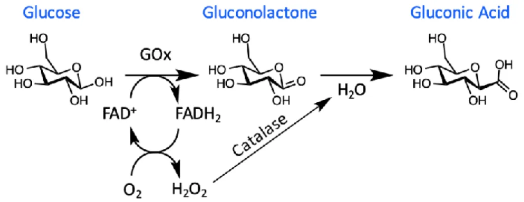
Blood-glucose concentrations are typically in the range of 4.9–6.9 mM for healthy patients, increasing to up to 40 mM in diabetics after glucose intake [66–72]. The first generation of glucose biosensors proposed by Clark and Lyons at the Children’s Hospital in Cincinnati in 1962 [73]. These sensors were based on an electrochemical approach, which used the enzyme glucose oxidase (GOx) [68]. Electrochemical sensors were chosen for blood-glucose measurements due to their high sensitivity, on the order of µM to mM, good reproducibility and ease of fabrication at relatively low cost [66]. GOx was employed as the enzyme for the sensor, due to its high selectivity for glucose, high tolerance towards extreme changes in pH, temperature and ionic strength in comparison with other enzymes such as hexokinase and glucose-1- dehydrogenase [74-77]. A thin layer of the GOx enzyme was placed on a platinum electrode via a semipermeable dialysis membrane to fabricate the sensor. This sensor measured the decrease in oxygen concentration and the liberation of hydrogen peroxide, which was proportional to the glucose concentration. GOx catalyzes the oxidation of glucose to
gluconolactone in the presence of oxygen, while producing hydrogen peroxide (H2O2) and water as
by-products as seen in Figure 9 [66]. Gluconolactone further undergoes a reaction with water to produce the carboxylic acid product, gluconic acid. GOx requires a redox cofactor to carry out this oxidation process, where flavin adenine dinucleotide (FAD+) is employed. FAD+ is an electron acceptor which
28
produce H2O2 regenerates the FAD+ cofactor. This reaction occurs at the anode, where the number of
transferred electrons can be correlated to the amount of H2O2 produced and, hence, the concentration
of glucose.
Figure 9. Conversion of glucose to gluconic acid using glucose oxidase.
The main obstacle to overcome with this approach is the interference of other electroactive species present in blood, such as ascorbic acid and urea [68,79]. In the design of these sensors, oxygen was employed as the electron-acceptor, which can result in errors from variations in oxygen tension and limitations, known as the oxygen deficit [80]. In order to overcome these challenges, oxygen was replaced with a synthetic electron redox mediator in second generation sensors [30].
The evolution of this sensing approach also led to the development of disposable enzyme electrode strips, which were accompanied by a pocket-size blood-glucose meter [81,82]. Each strip housed miniaturized screen-printed working and reference electrodes, where the working electrode was coated with the required sensing components; glucose oxidase, an electron-shuttle redox mediator, stabilizer and crosslinking agent. Currently, the most widely used self-monitoring method is the ‘finger-pricking’ approach which involves using a test strip to sample blood from a finger via pricking, which is then analyzed via a glucometer as seen in Figure 10 [83-92]. The effectiveness of this method relies on strict compliance, which can be negatively influenced by time constraints, pain, and inconvenience [93]. It is also not a continuous monitoring approach and needs to be carried out at multiple intervals
throughout the day to help manage elevated glucose levels [88-94], especially after meals, exercise and dosing of insulin medication [94,95]. Moreover, a non-continuous method such as this can overlook periods of hyper- or hypoglycemia which occur outside of the sampling window [93]. Recent developments in implantable sensors, on the other hand, can be used to incorporate insulin pumps, which allow for instant insulin administration [92,93,95].
Figure 10. Illustration of a A) Glucometer [86] and B) Continuous glucose monitor (CGM). [102].
In the early 1970s, Albisser et al. and Shichiri et al. first introduced the in vivo continuous glucose monitoring system using an artificial pancreas [98,99]. The artificial pancreas design was based on continuous glucose monitoring, where the device would remove blood from the body to an external benchtop analyzer that was connected to an insulin pump. As the name suggests, the device was not implanted and therefore not portable, although it was named the ‘artificial pancreas’. This led to the development of a third generation of glucose biosensor, which was subcutaneously implanted as seen in Figure 9.
Although the device could analyze glucose concentrations in blood using GOx, this was considered an invasive method [100]. The first commercially available personalized in vivo glucose
30
monitor was launched by Medtronic Minimed Inc. in the 1990s [79]. Unfortunately, the device could not provide real-time information, with data being accessed by a physician every 3 days [68]. Although implantable glucose monitoring systems offer regular glucose level readings, this approach isn’t recommended for all diabetics, due to its invasive nature [68] and some continuous glucose monitoring methods have been reported to show inaccuracies of up to 21% [101]. These inaccuracies are often attributed to sensor drift, caused by changes in the catalytic performance of the enzyme. This requires the device to be periodically recalibrated via the finger-pricking method [102]. Despite current commercially available glucometers, such as the Freestyle-Navigator by Abbott (Abbott Park, IL, USA), providing real-time measurements every 1–5 min, the longest working model without calibration is approximately two weeks. There is high consumer demand for a continuous glucose monitoring system which can quantify glucose concentrations without frequent calibration. Although blood remains the most studied body fluid for such measurements, other more accessible biological fluids such as interstitial fluid, ocular fluid, sweat, breath, saliva or urine have been investigated as alternative sample media for noninvasive continuous monitoring (Table 2) [66–69].
Table 2. Glucose concentration in physiological fluids for healthy and diabetic patients in mM Physiological Fluid Biomarker Concentration for Healthy Patients’ Concentration for Diabetic Patients’ pH Blood Glucose 4.9–6.9 mM 2–40 mM 7.35–7.45
Interstitial Fluid Glucose 3.9–6.6 mM 1.99–22.2 mM 7.2–7.4
Urine Glucose 2.78–5.55 mM >5.55 mM 4.5–8
Sweat Glucose 0.06–0.11 mM 0.01–1 mM 4.5–7
Saliva Glucose 0.23–0.38 mM 0.55–1.77 mM 6.2–7.6
Glucose monitoring in alternative physiological fluids
Interstitial fluid is the extracellular fluid which surrounds tissue cells. It has significant potential for medical diagnostics as it possesses a similar composition of several clinically important biomarkers to blood [103,104]. Blood and the surrounding vascularized tissue readily exchange biological analytes and small molecules by diffusion with the interstitial fluid [104]. As a result, interstitial fluid can offer valuable information about a patient’s health and has been used for minimally invasive determination of inherited metabolic diseases, organ failure or drug efficacy.
Sode et al. have also developed a self-powered implantable continuous monitoring device called the BioRadioTransmitter for use in an artificial pancreas [68]. In this instance, the device is composed of a capacitor, radio transmitter and receiver. In the presence of glucose, the capacitor of the BioRadioTransmitter device discharges a radio signal, which is received and amplified by the radio receiver. The change in transmission frequency is then related to the glucose concentration [105]. Microneedles and microneedle arrays have also garnered a lot of interest over recent years for interstitial fluid sensing, since this approach can offer minimally invasive methods for biosensing. This concept was used in the development of a glucose-sensing patch by Jina et al. [106]. The device was designed in two compartments: the first containing the microneedle array and glucose biosensor with the second containing the electronics as illustrated in Figure 11.
32
Figure 11. Schematic of the microneedle glucose-sensing patch on the forearm [69].
A microneedle patch platform allows the device to be in constant contact with the skin, providing permanent access to the interstitial fluid, and enabling this device to operate continuously [69]. In this particular case, the short length of the microneedles means that penetration is optimal for interstitial fluid sampling. Currently, the device must be recalibrated daily by the finger-prick approach [106]. Potential clogging of the microneedles and the distortion of their shape upon penetration of the skin can also affect the dynamics of sampling. Despite these shortcomings, this novel device holds great potential for non-invasive continuous glucose monitoring.
Urine has been used as a diagnostic fluid for diabetes since the 1980s due to its easy and non-invasive collection [107]. Urine is composed of metabolites, such as glucose, proteins and nitrates, as well as other dissolved salts, such as sodium and potassium. As a result, the pH of urine fluctuates between acidic pH 4.5 to basic pH 8 [108]. Due to the intermittent nature of this fluid, where collection is required for sampling, it cannot be incorporated into a continuous glucose-monitoring device.
Sweat is one of the most accessible body fluids. Eccrine glands that excrete sweat can be found all over the body [110]. Sweat has been used for the detection of disease markers such as sodium,
potassium, calcium, phosphate and glucose. The reported glucose level in sweat for healthy patients is between 0.06 and 0.11 mM and between 0.01 and 1 mM for diabetics [109]. The fluctuations in analyte concentrations result in a broad pH range of sweat, typically between pH 4.0–6.8 during exercise [111,112], which can impact the effectiveness of chemical sensing or biosensing techniques chosen for disease diagnosis or monitoring.
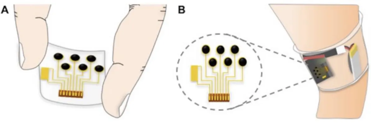
A non-invasive and continuous wearable glucose sweat sensing device was recently reported by Gao et al. [113]. It detects skin temperature, sodium, potassium, lactate and glucose concentrations in sweat [113]. An advantage of this approach is the use of multiple sensors which overcomes limitations of single, stand-alone sensors by providing a more comprehensive profile of sweat composition and enables data cross-comparisons. It is known that the potassium concentration in sweat is very stable during basal and exercising states. As a result, potassium levels can be used as a reference for comparing the fluctuating concentrations of other analytes, such as glucose, for performing concentration calculations. This sensor showed good correlations to the normal concentration ranges in sweat during exercise, but the drawback is that the glucose and lactate sensing units had to be changed every 2 hours to get continuous monitoring. Also, a minimum 10 µL of sweat was required to do sweat analysis. The sensors were placed close to the skin, to allow for immediate analysis of sweat as it emerged. The illustration can be seen in Figure 12.
34 noninvasive sensing in sweat [113].
Microsoft has collaborated with Drew Evans’ group from the University of South Australia (Mawson Lakes, SA, Australia) to design hydrophilic organic electrodes that could be incorporated into flexible hydrogels, such as a contact lens [114]. In their approach, they have fabricated conductive polymeric coatings that were engineered to be biocompatible and could be grown directly on to a contact lens. The conductive polymer poly-(3,4-ethylene-dioxythiophene (PEDOT) was deposited on to the lens using oxygen plasma techniques. This lens was designed to advance the development of silicone hydrogels with technologically relevant properties, such as conductivity and pave the way for conductive hydrogel electrodes [114]. Ultimately, this lens would self-report relating optical changes to glucose concentrations. An advantage of this passive device is that no batteries or wireless connections are required to receive and transmit crucial information.
Wearable sensors have the potential to play a major role in the continuous and non-invasive monitoring of biomarkers for diabetes and other disease conditions. The interest of companies such as Google, Novartis and Microsoft suggest there is a significant market potential for new approaches to self-monitoring and disease diagnosis. Glucose biosensors are constantly evolving as per the demand and there is a need for a self-powered glucose biosensing microsystem which will eliminate the dependence of batteries as the power source, glucometers and CGM devices, thereby improving the standard of living of people suffering from diabetes.


![Figure 11. Schematic of the microneedle glucose-sensing patch on the forearm [69].](https://thumb-us.123doks.com/thumbv2/123dok_us/8663065.2341030/45.918.259.712.113.370/figure-schematic-microneedle-glucose-sensing-patch-forearm.webp)
![Figure 14. Reconfiguring of the basic boost-converter charge pump results in a circuit which converts a positive rail to a negative one needed for biasing or providing an offset voltage [116]](https://thumb-us.123doks.com/thumbv2/123dok_us/8663065.2341030/51.918.179.741.99.419/figure-reconfiguring-converter-results-converts-positive-negative-providing.webp)
