Accelerating Databases and Applications ...8
Virtualizing and Consolidating Workloads ...8
Delivering the Ultimate Virtual Desktop Experience ...8
Protecting and Recovering Vital Data Assets...8
Consistent Performance ...8
Less Cost than Disk ...8
Mission-critical Resiliency ...8
Disaster Recovery Built-In ...8
Simplicity Built-In ...8
Start Small and Grow Online ...9
Pure Storage FA-420 Configuration ... 15
Setup Windows Server 2012 R2 ... 18
Setup Windows Server Failover Cluster (WSFC) ... 18
Pure Storage FA-405 Configuration ... 37
Setup Windows Server 2012 R2 ... 40
Setup Pure Storage Volume for the Clustered Shared Volume ... 41
Setup Windows Server Failover Cluster (WSFC) ... 43
Setup Hyper-V Failover Cluster ... 45
Setup Pass-Through Disks for Hyper-V Highly Available Virtual Machines ... 52
Setup Microsoft SQL Server 2014 ... 59
This document provides a reference architecture for deploying Microsoft SQL Server 2014 AlwaysOn Availability Groups on a Pure Storage FlashArray. This document includes step-by-step guidance on deploying a primary and disaster recovery site for high availability.
The primary site is based on a Windows Server Failover Cluster that will be used with a Microsoft SQL Server 2014 AlwaysOn Availability Group with two physical server nodes for the primary replica and secondary replica. Two virtualized Windows Server 2012 R2 nodes based on VMware ESX 5.5 will be created for two additional secondary replicas. The disaster recovery site is based on a Windows Server Failover Cluster to create a highly available Hyper-V instance for a SQL Server 2014 stand-alone server. The primary site will use Pure Storage FlashRecover Replication to replicate the AlwaysOn Availability Group data volumes to the disaster recovery site to be used with the SQL Server 2014 stand-alone server. FlashRecover replication can easily replicate data volumes and maintain data synchronization based on a configurable schedule.
This reference architecture has been validated against:
Microsoft Windows Server 2012 R2, Data Center Edition (64-bit)
Microsoft SQL Server 2014 Enterprise (64-bit)
Microsoft Hyper-V Failover Cluster
VMware ESX 5.5
Pure Storage FlashArray 420 (FA-420)
Pure Storage FlashArray 405 (FA-405)
Purity Operating Environment 4.0.x
Windows PowerShell 5.0 (November Preview)
Pure Storage PowerShell Toolkit 2.0
Before we begin diving into the setup details it is important to have a foundation on how SQL Server AlwaysOn works and the different models that are supported. Microsoft SQL Server 2012 and 2014 supports two different clustering models. The first is AlwaysOn Failover Cluster Instance (FCI). An AlwaysOn FCI provides server hardware fault tolerance and is equivalent to Microsoft SQL clustering provided by earlier versions of Microsoft SQL Server. FCI provides automatic failover to the other nodes in the cluster if there is a hardware, service or other system failures.
The second is AlwaysOn Availability Groups. AlwaysOn Availability Groups provide synchronous and asynchronous replication between servers in a Windows Failover Cluster. AlwaysOn Availability Groups can provide server fault tolerance, storage fault tolerance, and automated load distribution. AlwaysOn Availability Groups require a minimum of Microsoft SQL Server 2012 Enterprise Edition, this paper uses Microsoft SQL Server 2014 Enterprise Edition.
To participate in AlwaysOn Availability Groups or AlwaysOn Failover Cluster Instances, the servers on which Microsoft SQL Server 2012 are installed must be part of the same Windows Failover Cluster. AlwaysOn Availability Groups allow two (2) database instances installed on different physical servers to replicate synchronously or asynchronously. Microsoft SQL Server 2012 supports a single primary replica and one to four secondary replicas; SQL Server 2014 supports up to eight secondary replicas. During normal operations, one instance will be read-write, and the other will be read-only. If the read-write node fails, the read-write functionality will automatically transfer to the read-only instance. Transactions which write to the database will only be acknowledged as completed when the transaction has been written to both instances. The read-only instance can be used for read-only transactions, thus reducing the load on the read-write instance. Microsoft SQL Server 2012/2014 can automatically direct read-only transactions to the read-only instance of the database. As a best practice, Microsoft SQL should handle this load
balancing. Manually configuring clients to connect to only one database instance is not a best practice and is not recommended.
A key tenet with Pure Storage FlashArray is the simplicity of management and this document is intended to demonstrate how easily Microsoft SQL Server 2014 AlwaysOn Availability Groups can be deployed and managed on a Pure Storage FlashArray. In addition to deploying AlwaysOn we will cover how easy it is to setup and manage Pure Storage FlashRecover Replication. We will explore how the AlwaysOn Availability Group can be replicated over to a secondary Pure Storage FlashArray and used within a Microsoft Hyper-V Failover Cluster with SQL Server 2014. Additionally as part of the setup and deployment of SQL Server AlwaysOn we will use Pure Storage FlashRecover snapshots to rapidly seed the secondary replicas.
Leveraging FlashRecover snapshots provides a considerable savings in time for initial data synchronization to the secondary replicas and save on network traffic.
This document is intended for Database Administrators (DBAs), Storage Administrators, System
Administrators and anybody who wants to deploy a (1) Microsoft SQL Server AlwaysOn solution and (2) a Microsoft Hyper-V Failover Cluster on a Pure Storage FlashArray. This is a technical document that assumes a working knowledge of Windows Server 2012 R2, Microsoft Hyper-V, Windows Server Failover Clustering Windows PowerShell and familiarity with storage provisioning and networking. These are not
prerequisites to reviewing this document but are highly recommended to understand all of the different components.
This reference architecture can be treated as a building block on how to deploy a highly available solution for SQL Server AlwaysOn Availability Groups and a Microsoft Hyper-V failover cluster. There are a lot of
different components to the solution outlined in this paper and can be used together as this paper illustrates or only certain elements used in your environment.
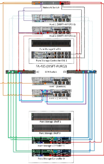
The deployment of this reference architecture covers two different sites that comprise a primary site that is used for day to day operations and a disaster recovery (DR) site which can be used DR or other purposes
(Eg. Dev/Test). The primary site contains a Windows Server 2012 R2 Failover Cluster with two physical and two virtual hosts. These cluster nodes make up all of the members for a SQL Server 2014 Availability Group. All of the operational work taking place on the primary site is served by a Pure Storage FA-420. The DR site contains a two node Windows Server 2012 R2 Failover Cluster which uses a Clustered Shared Volume (CSV) for highly-available Hyper-V virtual machines instances. The workloads in DR are supported by a Pure Storage FA-405. The primary site and the DR site are connected through Pure Storage
FlashRecover Replication. All of these components are visualized in Figure 1.
Figure 1. Primary and Disaster Recovery sites.
The business advantages of the core technologies used in this reference architecture are described below. AlwaysOn Availability Groups provide a quick and easy method to scaling-out SQL Server to
accommodate a multitude of workloads. Part of the process for setting up AlwaysOn is the need to “seed” the secondary replicas from the primary replica. Using Pure Storage FlashRecover it is possible to seed all of the secondary replicas without incurring all of the network bandwidth and host penalties that host based copy processing can cause. Another advantage of AlwaysOn Availability Groups compared to database mirroring is that there can be a maximum of two synchronous replicas versus with database mirroring DBAs were forced to use either high-safety mode (synchronous) or high-performance mode (asynchronous). AlwaysOn allows for a best of both worlds scalable architecture.
The use of Windows Server Failover Clustering with SQL AlwaysOn Availability Groups in the primary site is greatly simplified without the need for Clustered Shared Volumes (Shared Storage). With the use of Pure Storage FlashRecover snapshots of a SQL Server backup volume it provides a
rapid seeding of each secondary replica without relying on host-to-host copy data synchronization of files. Additionally, once the secondary replicas have been seeded and joined to the Availability Group the ability to use a secondary replica as a backup instance is extremely beneficial for the primary replicas performance.
The disaster recovery site uses a Clustered Shared Volume (CSV) and Pass-Through Disks allows for creating a highly available Hyper-V virtual machines and attached directly to the Pure Storage volumes for optimal performance. Not needing to use a CSV eliminates IO redirection issues through the Owner Node.
Paired use of Pure Storage FlashRecover Replication with the previously mentioned benefits of highly available Hyper-V virtual machines allows for primary to disaster recovery sites to replicate specific volumes, hosts or host groups and have limited downtime.
Finally, the ability to setup this solution using Windows PowerShell with the new Pure Storage PowerShell Toolkit 2.0 and the support through cmdlets for Windows Server Failover Clustering, Hyper-V and SQL Server provides a tremendous automation framework for repeatable and rapid deployments. Please refer to Appendix I: Install Pure Storage PowerShell Toolkit 2.0.
There is an incredible amount of detail covered in this paper that can be used in many different ways to help a business achieve new levels of availability and Service Level Agreements (SLAs). Before we begin walking through deployment steps it is important to understand the basic capabilities that the Pure Storage All-Flash platform provides.
Pure Storage is the leading all-flash enterprise array vendor, committed to enabling companies of all sizes to transform their businesses with flash.
Built on 100% MLC flash, Pure Storage FlashArray delivers all-flash enterprise storage that is 10X faster, more space and power efficient, more reliable, and infinitely simpler, and yet typically cost less than traditional performance disk arrays.
Pure Storage FlashArray FA-400 Series is ideal for: FA-405
FA-420
Speed transactions by 10x with consistent low latency, enable online data analytics across wide datasets, and mix production, analytics, dev/test, and backup workloads without fear.
Easily accommodate the most IO-hungry Tier 1 workloads, increase consolidation rates (thereby reducing servers), simplify VI administration, and accelerate common administrative tasks.
Support demanding users with better performance than physical desktops, scale without disruption from pilot to >1000’s of users.
Provide an always-on protection for business-critical data, maintain performance even under failure conditions, and recover instantly with FlashRecover.
Pure Storage FlashArray sets the benchmark for all-flash enterprise storage arrays. It delivers:
FlashArray delivers consistent <1ms average latency. Performance is optimized for the real-world applications workloads that are dominated by IO sizes of 32K or larger vs. 4K/8K hero performance benchmarks. Full performance is maintained even under failures/updates.
Inline de-duplication and compression deliver 5 – 10x space savings across broad set of IO workloads including Databases, Virtual Machines and Virtual Desktop Infrastructure.
FlashArray delivers >99.999% proven availability, as measured across the Pure Storage installed base and does so with non-disruptive everything without performance impact.
FlashArray offers native, fully integrated, data reduction-optimized backup and disaster recovery at no additional cost. Setup disaster recovery with policy-based automation within minutes. And, recover instantly from local, space-efficient snapshots or remote replicas.
FlashArray offers game-changing management simplicity that makes storage installation, configuration, provisioning and migration a snap. No more managing performance, RAID, tiers or caching. Achieve
optimal application performance without any tuning at any layer. Manage the FlashArray the way you like it: Web-based GUI, CLI, VMware vCenter, Rest API, or OpenStack.
Pure Storage FlashArray FA-400 Series includes FA-405, FA-420, and FA-450. A FlashArray is available for any application and any budget!
Table 1. Pure Storage FlashArray 400 Series Specifications.
FlashArray scales from smaller workloads to data center-wide consolidation. And because upgrading performance and capacity on the FlashArray is always non-disruptive, you can start small and grow without impacting mission-critical applications. Coupled with Forever Flash, a new business model for storage acquisition and lifecycles, FlashArray provides a simple and economical approach to evolutionary storage that extends the useful life of an array and does away with the incumbent storage vendor practices of forklift upgrades and maintenance extortion.
The following section describes the different components and configurations for the primary and disaster recovery sites. Figure 2 illustrates the hardware configuration. There are two additional servers (hosts) that are not displayed in the Figure 2 diagram that represent the VMware ESX cluster. These hosts are connected to the FA-420 and FA-405 via the SAN switch represented in the diagram.
Figure 2. Component connectivity.
The focus of this paper is to show the configuration steps necessary to setup a Windows Failover Clusters, SQL Server AlwaysOn, Hyper-V failover cluster and FlashRecover Replication. This paper will not cover any details related to configuration of VMware ESX or vSphere, please refer to the Pure Storage and VMware vSphere Best Practices Guide for specific guidance. We will also not be covering any of the physical servers (hosts) setup or switch zoning, please refer to the specific hardware documentation for configuration.
The FlashArray FA-420 configuration comprised of two active/active controllers and two shelves of 5.5TB of raw flash memory for a total of 11TB of raw storage. Four Fibre Channel ports per controller were connected to one Cisco MDS 9148 8Gb SAN switches in a highly redundant configuration as shown in
Figure 2. There are two additional servers (hosts) that are not displayed in the diagram that represent the VMware ESX cluster. These hosts are connected to the FA-420 and FA-405 via the SAN switch represented in the diagram. Table 2 below describes the specifications of the FlashArray FA-420.
Component Description
Controllers Two active/active controllers which provided highly redundant SAS connectivity (24Gb) to two shelves and were interconnected for HA via two redundant InfiniBand connections (56Gb).
Shelves Two flash memory shelves with 22 SSD drives, 22 X 256 GB or a total raw capacity of 11TB (10.3 TiB) and two NVRAM modules for a total of 24 slots in each shelf.
External Connectivity
Four 8Gb Fibre Channel ports per controller, total of eight ports for two controllers.
Management Ports
Two redundant 1 Gb Ethernet management ports per controller. Three management IP addresses are required to configure the array, one for each controller management port and a third one for virtual port IP address for seamless management access.
Power Dual power supply rated at 400W per controller and 200W per storage shelf.
Space The entire FA-420 system was hosted on eight rack units (8 RU) space (2 RU for each controller and 2 RU for each flash memory shelf). This configuration could easily scale to four shelves and 3X the capacity discussed in the test system used.
Table 2. Pure Storage FlashArray FA-420 specifications
There was no special configuration or tuning done on the FlashArray; we do not recommend any special tunable variables as the system is designed to perform out of the box.
The FlashArray FA-405 configuration comprised of two active/active controllers and a single shelf of 5.5TB of raw flash memory storage. Two Fibre Channel ports per controller were connected to one Cisco MDS 9148 8Gb SAN switches in a highly redundant configuration as shown in Figure 2. Table 3 below describes the specifications of the FlashArray FA-420.
Component Description
Controllers Two active/active controllers which provided highly redundant SAS connectivity (24Gb) to two shelves and were interconnected for HA via two redundant InfiniBand connections (56Gb).
Shelves One flash memory shelf with 22 SSD drives, 22 X 256 GB or a total raw capacity of 5.5TB (10.3 TiB) and two NVRAM modules for a total of 24 slots in each shelf.
External Connectivity
Two 8Gb Fibre Channel ports per controller, total of four ports for two controllers.
Management Ports
Two redundant 1 Gb Ethernet management ports per controller. Three management IP addresses are required to configure the array, one for each controller management port and a third one for virtual port IP address for seamless management access.
Power Dual power supply rated at 300W per controller and 200W per storage shelf.
Space The entire FA-405 system was hosted on four rack units (4 RU) space (2 RU for the controller and 2 RU for the flash memory shelf).
Table 3. Pure Storage FlashArray FA-405 specifications
There was no special configuration or tuning done on the FlashArray; we do not recommend any special tunable variables as the system is designed to perform out of the box.
Four Dell PowerEdge R720xd servers were deployed for hosting the following:
Two servers for hosting physical deployments of Microsoft Windows Server 2012 R2 and Microsoft SQL Server 2014.
Two servers for hosting VMware ESX 5.5 for the primary site virtualized Windows Server 2012 R2 and SQL Server 2014 instances.
Each of the server’s dual HBA ports were connected to two Cisco MDS 9148 switches for upstream connectivity to access the Pure Storage FlashArray FA-420. The server configuration is described in the Table 4.
Component Description
Processor 2 Intel® Xeon® CPU E5-2697 v2 @ 2.70GHz, 2700 Mhz, 12 Core(s), 24 Logical
Memory 256GB
HBA 2 QLogic (QLE2562) 8 Gbps Fibre Channel HBA’s (2 ports each)
NIC Intel(R) Gigabit 4P X520/I350 rNDC
BIOS Dell Inc. 2.1.3, 11/20/2013; SMBIOS 2.7
OS Microsoft Windows Server 2012 R2 Datacenter, Version 6.3.9600 Build 9600 (x64)
Table 4. Dell R720xd host configuration
The disaster recovery site consists of two American Megatrends (AMI) servers deployed for hosting a Microsoft Windows Server 2012 R2 Failover Cluster and a highly available Hyper-V failover cluster. The server’s dual HBA ports were connected to two Cisco MDS 9148 switches for upstream connectivity to access the Pure Storage FlashArray FA-405. The server configuration is described in the Table 5.
Component Description
Memory 96GB
HBA 2 QLogic (QLE2562) 8 Gbps Fibre Channel HBA’s (2 ports each)
NIC Intel(R) 82574L Gigabit (1Gbps)
BIOS American Megatrends, Inc. HS-1235T-ATX BIOS Version 1.60
OS Microsoft Windows Server 2012 R2 Datacenter, Version 6.3.9600 Build 9600 (x64)
Table 5. American Megatrends Server host configuration
Now all of the hardware and logical design details are out of the way it is time to begin setting up the primary and disaster recovery sites.
The primary site in this configuration is the where the main database servers will reside. This configuration will use Windows Server Failover Cluster and VMware ESX as the core infrastructure providing physical and virtualized SQL Server services respectively. There are some configurations that are assumed to be
completed prior to starting the step-by-step guides provide below. Assumptions:
1. One Pure Storage FlashArray FA-420 has been installed and configured.
2. Four physical servers have been installed and configured. Two servers have Windows Server 2012 R2 deployed and all Windows Server Best Practices for Pure Storage followed. The remaining two servers have VMware ESX 5.5 deployed with all Pure Storage best practices followed for VMware. 3. All four physical servers have been connected through a SAN and networking fabric.
4. Windows PowerShell 3.0 and the Pure Storage PowerShell Toolkit 2.0 have been installed. The primary site setup section describes step-by-step how to configure all of the components for Microsoft SQL Server 2014 AlwaysOn with multiple replicas. The following tasks are what we will be performing:
Creating Host Groups and adding Hosts on the Pure Storage FA-420.
Create a Microsoft Windows Server Failover Cluster.
Create a SQL Server AlwaysOn Availability Group.
Create a FlashRecover snapshot that will be used to seed the secondary replicas for the AlwaysOn Availability Group member servers.
Before we can begin creating any of the core infrastructure for the primary site the Pure Storage FA-420 needs to be setup with Host Groups and have Hosts connected to those groups. The steps in this section makes the assumption that the hardware requirements in the Configuration Overview are the same or similar in your environment. If your setup does not meet those requirements modifications will need to be made in order to follow the steps.
Assuming that the physical hosts are connected to the array and configured as in Figure 3 we can create the Host Groups that will be used for the ESX and Windows Server Failover Cluster.
Figure 3. Pure Storage FA-420 Host Connections.
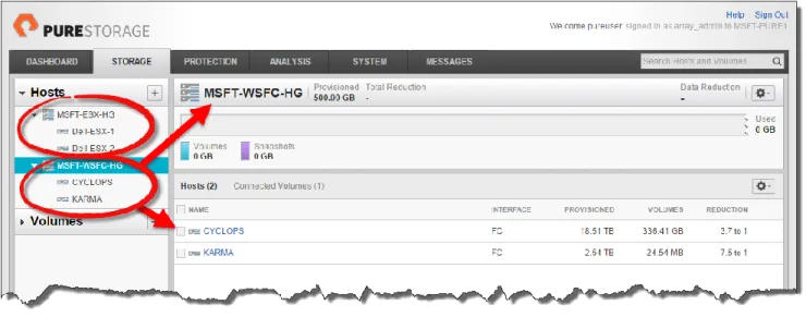
The Host Group names are MSFT-WSFC-HG and MSFT-ESX-HG. The following PowerShell will create the host groups and connect the existing hosts to those groups. This operation can also be performed using
the Web Management GUI.
Import-Module PureStoragePowerShell
$PSToken = Get-PfaApiToken -FlashArray MSFT-PURE1 -Username pureuser -Password pureuser $PSSession = Connect-PfaController -FlashArray MSFT-PURE1 -API_Token $PSToken.api_token New-PfaHostGroup -FlashArray MSFT-PURE1 -Name MSFT-WSFC-HG `
-HostList CYCLOPS,KARMA -Session $PSSession
New-PfaHostGroup -FlashArray MSFT-PURE1 -Name MSFT-ESX-HG ` -HostList Dell-ESX-1,Dell-ESX-2 -Session $PSSession Figure 4 shows the newly created host groups and connected hosts.
Figure 4. MSFT-ESX-HG and MSFT-WSFC-HG host groups.
The next step is to create the different volumes that each of the hosts will use. This paper will show how to create the volumes for SQL Server data files only. As mentioned earlier details to create and connect the volumes required for VMware datastores is out of scope for this paper please refer to the Pure Storage and VMware vSphere Best Practices Guide.
Per the SQL Server 2012 Reference Architecture we will create three volumes to be used by SQL Server 2014; SQLSYS and SQLTEMP for system databases and tempdb and ADVWORKS-AG for the
AdventureWorks Availability Group. This is the volume we will be working with throughout the primary and disaster recovery work and replication. This operation can be performed using the GUI as well. Import-Module PureStoragePowerShell
$PSToken = Get-PfaApiToken -FlashArray MSFT-PURE1 -Username pureuser -Password pureuser $PSSession = Connect-PfaController -FlashArray MSFT-PURE1 -API_Token $PSToken.api_token New-PfaVolume -FlashArray MSFT-PURE1 -Name CYCLOPS-SQLSYS -Size 50G -Session $PSSession New-PfaVolume -FlashArray MSFT-PURE1 -Name CYCLOPS-SQLTEMP -Size 1T -Session $PSSession New-PfaVolume -FlashArray MSFT-PURE1 -Name CYCLOPS-ADVWORKS-AG -Size 500G `
-Session $PSSession
Connect-PfaHost -FlashArray MSFT-PURE1 -Name CYCLOPS -Volume CYCLOPS-SQSYS `
-Session $PSSession
Connect-PfaHost -FlashArray MSFT-PURE1 -Name CYCLOPS -Volume CYCLOPS-SQLTEMPDB `
-Session $PSSession
Connect-PfaHost -FlashArray MSFT-PURE1 -Name CYCLOPS -Volume ADVWORKS-AG `
-Session $PSSession
New-PfaVolume -FlashArray MSFT-PURE1 -Name KARMA-SQLSYS -Size 50G -Session $PSSession New-PfaVolume -FlashArray MSFT-PURE1 -Name KARMA-SQLTEMP -Size 1T -Session $PSSession Connect-PfaHost -FlashArray MSFT-PURE1 -Name KARMA -Volume KARMA-SQSYS -Session $PSSession Connect-PfaHost -FlashArray MSFT-PURE1 -Name KARMA -Volume KARMA-SQLTEMPDB `
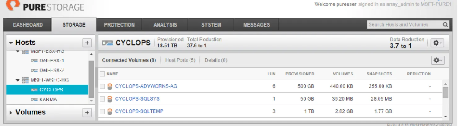
Figure 5 shows the newly created and connected volumes for CYCLOPS.
Figure 5. New volumes for SQL Server instances on CYCLOPS and KARMA.
Once the volumes are created rescan the hosts for those volumes to be mounted for Windows Server to see and use as shown in Figure 6.
Register-PfaHostVolumes -Computername CYCLOPS Register-PfaHostVolumes -Computername KARMA
It is assumed that Windows Server 2012 R2 has been installed and configured per the Windows Server Best Practice Guide available on the Pure Storage Community site. This would include installing and configuring MPIO and all appropriate updates.
Add required Windows Server Failover Clustering features on both CYCLOPS and KARMA. The cmdlets below can be specified to run against other servers without the need to be physically attached. Since the servers (hosts) in your environment will not mimic the documented test configuration replace the – ComputerName parameter with the appropriate name of servers to installs the features.
Add-WindowsFeature -Name Failover-Clustering -ComputerName CYCLOPS Add-WindowsFeature -Name RSAT-Clustering-Mgmt -ComputerName CYCLOPS Add-WindowsFeature -Name RSAT-Clustering-PowerShell -ComputerName CYCLOPS Add-WindowsFeature -Name RSAT-Clustering-AutomationServer -ComputerName CYCLOPS Add-WindowsFeature -Name RSAT-Clustering-CmdInterface -ComputerName CYCLOPS
Figure 7. Failover Clustering features installed on CYCLOPS and KARMA.
Add Windows features that are required for Microsoft SQL Server 2014: Add-WindowsFeature –Name NET-Framework-Features
This concludes the basic for the Windows Server Failover Cluster (WSFC) features prerequisites. Now let’s configure the WSFC.
Before creating a new cluster ensure both nodes of the cluster are at equivalent software update levels using Windows Update. If they are not this error will turn up in the Validation Configuration report.
The cluster Validation Configuration report may show a warning about not having a quorum disk. This can be ignored as Shared Storage, clustered shared volume, is not required for AlwaysOn.
Setting up a WSFC for use with Microsoft SQL Server 2014 AlwaysOn is quite simple, no shared storage is required so we can skip adding any storage to this cluster. You will notice the –NoStorage parameter which means the cluster will be created with the two hosts, assigned and IP address and brought online.
New-Cluster -Name PURE-FC1 -Node CYCLOPS,KARMA -StaticAddress 10.21.8.53 -NoStorage
Figure 8 shows all of the SQL Server nodes of the WSFC. The SQL-REPLICA3 and 4 are running on VMware virtual machines hosted on vSphere 5.5. These nodes were added using the Add-ClusterNode cmdlet.
As mentioned earlier understanding the details for installing SQL Server is covered in the SQL Server 2012 Reference Architecture and should be referred to for all basic setup and best practices. This section will solely focus on configuring and deploying a SQL Server AlwaysOn Availability Group.
There are four basic steps to setting up an AlwaysOn Availability Group:
1. Add the Failover Clustering feature to each Windows Server (completed!) 2. Create a Windows Failover Cluster (completed!)
3. Enable AlwaysOn High Availability Group feature for each SQL Server. 4. Create an Availability Group
SQL Server 2014 has been configured in the environment and there are several Microsoft AdvenutreWorks databases (AdventureWorks2014, AdventureWorksLegal, AdventureWorksHR, AdventureWorksFinance) attached to the CYCLOPS default instance as shown in Figure 9. All of these databases will be part of an AlwaysOn Availability Group. Not shown but an important point is that all of the AdventureWorks databases reside on A:\ADVWORKS. The importance of this detail will become apparent further into the configuration steps.
Any database that is to be part of an AlwaysOn Availability Group has two pre-requisites; (1) database must be in full recovery model and (2) at least one full backup must be performed in order to
initialize the log backup chain. A transaction log backup is also required to restore on the secondary replicas.
A pre-requisite is to have a full backup of each of these databases. Typically this backup (BAK) would then be placed on in a network share that is available to all nodes of the cluster or use a Clustered Shared Volume (CSV) for all the cluster nodes to have shared access. For this paper we are going to make use of Pure Storage FlashRecover snapshots between all of the different cluster nodes. The basic steps are as follows:
1. Create a new Pure Storage volume to store the primary replica SQL Server backups and connect to the primary replica host.
2. Take full backups of the individual SQL Server databases and store on the newly created volume in Step 1. Now there is a set of full backups for the individual databases.
3. Using Pure Storage FlashRecover take a snapshot of the backup volume.
4. Create a new volume from the backup volume snapshot and attach to each individual node of the cluster, not to the cluster itself.
5. Run a restore database operation on each of the SQL Server nodes and then join to the Availability Group.
By using the operational steps above we have a full backup of the databases to start. A snapshot of that backup volume has been created to rapidly seed other Availabilty Group members without introducing network bandwidth through SQL Server data synchronization.
The first step is to create the new volume to be used for SQL Server backups and connect to the primary replica. Figure 10 and Figure 11 shows the respective results on the FlashArray and the host CYCLOPS. Import-Module PureStoragePowerShell
$PSToken = Get-PfaApiToken -FlashArray MSFT-PURE1 -Username pureuser -Password pureuser $PSSession = Connect-PfaController -FlashArray MSFT-PURE1 -API_Token $PSToken.api_token New-PfaVolume -FlashArray MSFT-PURE1 -Name CSV -Size 1T -Session $PSSession
Connect-PfaHost -FlashArray MSFT-PURE1 -Name CYCLOPS -Volume CYCLOPS-SQLBAK `
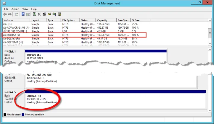
Figure 10. Created and connected CYCLOPS-SQLBAK volume.
Figure 11. New SQLBAK volume mounted to the CYCLOPS host.
The next step is to create a full database and transaction log backup of each of the databases we are using in the Availability Group; AdventWorks2014, AdventureWorksHR, AdventureWorksFinance and
AdventureWorksLegal. The following T-SQL will perform this task. A folder named I:\ADVWORKS will be created on the new volume (I:\) automatically. This procedure can also be done using SQL Server Management Studio if preferred.
EXEC master.sys.xp_create_subdir "I:\ADVWORKS"
USE AdventureWorks2014; GO
BACKUP DATABASE AdventureWorks2014
TO DISK = 'I:\ADVWORKS\AdventureWorks2014.Bak'
WITH FORMAT,
NAME = 'Full Backup of AdventureWorks2014'; GO
BACKUP LOG AdventureWorks2014
TO DISK = 'I:\ADVWORKS\AdventureWorks2014TLOG.Bak'
WITH FORMAT,
NAME = 'TLOG Backup of AdventureWorks2014'; GO
USE AdventureWorksFinance; GO
BACKUP DATABASE AdventureWorksFinance
TO DISK = 'I:\ADVWORKS\AdventureWorksFinance.Bak'
WITH FORMAT,
NAME = 'Full Backup of AdventureWorksFinance'; GO
BACKUP LOG AdventureWorksFinance
TO DISK = 'I:\ADVWORKS\AdventureWorksFinanceTLOG.Bak'
WITH FORMAT,
NAME = 'TLOG Backup of AdventureWorksFinance'; GO
USE AdventureWorksHR; GO
BACKUP DATABASE AdventureWorksHR
TO DISK = 'I:\ADVWORKS\AdventureWorksHR.Bak'
WITH FORMAT,
NAME = 'Full Backup of AdventureWorksHR'; GO
BACKUP LOG AdventureWorksHR
TO DISK = 'I:\ADVWORKS\AdventureWorksHRTLOG.Bak'
WITH FORMAT,
NAME = 'TLOG Backup of AdventureWorksHR'; GO
USE AdventureWorksLegal; GO
BACKUP DATABASE AdventureWorksLegal
TO DISK = 'I:\ADVWORKS\AdventureWorksLegal.Bak'
WITH FORMAT,
NAME = 'Full Backup of AdventureWorksLegal'; GO
BACKUP LOG AdventureWorksLegal
TO DISK = 'I:\ADVWORKS\AdventureWorksLegalTLOG.Bak'
WITH FORMAT,
NAME = 'TLOG Backup of AdventureWorksLegal'; GO
Now a snapshot can be taken of the CYCLOPS-SQLBAK volume. It is also possible to setup this volume as part of the local snapshot schedule using the Protection tab. Figure 12 shows the newly created snapshot.
Import-Module PureStoragePowerShell
$PSSession = Connect-PfaController -FlashArray MSFT-PURE1 -API_Token $PSToken.api_token New-PfaSnapshot -FlashArray MSFT-PURE1 -Volumes CYCLOPS-SQLBAK -Suffix REFARCH -Session $PSSession
Figure 12. New snapshot of the CYCLOPS-SQLBAK volume.
Before preparing your secondary databases, we strongly recommend that you suspend scheduled log backups on the databases in the availability group until the initialization of secondary replicas has completed.
Now that we have the full and transaction log backups completed and a snapshot taken we can create new volumes from the snapshot (CYCLOPS-SQLBAK.REFARCH) to the other secondary replicas. This involves connecting to both physical hosts (KARMA) and virtual hosts (SQL-REPLICA3 and SQL-REPLICA4). We know that there are three secondary replicas so we can quickly create three new volumes based on the CYCLOPS-SQLBAK.REFARCH snapshot with the following PowerShell. In addition to creating the three volumes for the backup restores, we also need to create three new volumes for the individual databases once restored on the secondary replicas. Figure 13 shows all the new volumes.
Import-Module PureStoragePowerShell
$PSToken = Get-PfaApiToken -FlashArray MSFT-PURE1 -Username pureuser -Password pureuser $PSSession = Connect-PfaController -FlashArray MSFT-PURE1 -API_Token $PSToken.api_token
ForEach ($i in 1..3) {
New-PfaVolume -FlashArray MSFT-PURE1 -Name AG-SQLBAK-RESTORE$i `
-Source CYCLOPS-SQLBAK.REFARCH -Session $PSSession
New-PfaVolume -FlashArray MSFT-PURE1 -Name AG-ADVWORKS$i -Size 1T -Session $PSSession }
Figure 13. Newly created volumes from the snapshot.
Next connect the volumes to the hosts and online the volumes for Windows Server to utilize. The last cmdlet executed Register-PfaHostVolumes makes the volume available on the host, KARMA.
Import-Module PureStoragePowerShell
$PSToken = Get-PfaApiToken -FlashArray MSFT-PURE1 -Username pureuser -Password pureuser $PSSession = Connect-PfaController -FlashArray MSFT-PURE1 -API_Token $PSToken.api_token Connect-PfaVolume -FlashArray MSFT-PURE1 -Name KARMA -Volume AG-SQLBAK-RESTORE1 `
-Session $PSSession
Connect-PfaVolume -FlashArray MSFT-PURE1 -Name KARMA -Volume AG-ADVWORKS1 `
-Session $PSSession
Register-PfaHostVolumes -Computername KARMA
Focusing on the host KARMA, shown in Figure 14, we can see that there are two new volumes connected, SQLBAK (K:\) and 1TB volume that has not been initialized. This uninitialized volume is one of the new volumes created from the above PowerShell. This volume needs to be initialized and formatted per the SQL Server 2012 Reference Architecture best practices. Once we have completed that operation we can proceed with restoring the database and transaction log backups.
One important detail to remember is the location of the primary replicas databases, which is on
A:\ADVWORKS. Creating an exact mirror of the file locality may not be possible in all environments so if the file paths of the primary replica database differ from the secondary replica the MOVE option (see
Appendix III) needs to be used either from SQL Server Management Studio or T-SQL. For this paper we are mirroring the file structure on all hosts with A:\ADVWORKS for the new volume. The below PowerShell will handle setting up the new volume.
$PSVOL = Get-Disk | Where-Object { $_.FriendlyName -like "PURE FlashArray*" -And ` $_.PartitionStyle -eq "RAW" }
Initialize-Disk -Number $PSVOL.Number -PartitionStyle GPT
$NEWSQLVOL = New-Partition -DiskNumber $PSVOL.Number -UseMaximumSize -DriveLetter A Format-Volume -DriveLetter $NEWSQLVOL.DriveLetter -FileSystem NTFS `
-NewFileSystemLabel "ADVWORKS-AG" -AllocationUnitSize 64KB -Force -Confirm:$False
Now that the new and backup volumes are connected we can proceed with a restore of the
AdventureWorks databases. The following T-SQL can be used to restore the database and transaction log backups. This can also be done using SQL Server Management Studio manually if preferred.
EXEC master.sys.xp_create_subdir "A:\ADVWORKS"
USE [master]
RESTORE DATABASE [AdventureWorks2014]
FROM DISK = N'F:\ADVWORKS\AdventureWorks2014.Bak' WITH
FILE = 1,
NORECOVERY,
NOUNLOAD,
STATS = 5
GO
RESTORE LOG [AdventureWorks2014]
FROM DISK = N'F:\ADVWORKS\AdventureWorks2014TLOG.Bak' WITH
FILE = 1,
NORECOVERY,
NOUNLOAD,
STATS = 10
GO
RESTORE DATABASE [AdventureWorksHR]
FROM DISK = N'F:\ADVWORKS\AdventureWorksHR.Bak' WITH
FILE = 1,
NORECOVERY,
NOUNLOAD,
STATS = 5
GO
RESTORE LOG [AdventureWorksHR]
FROM DISK = N'F:\ADVWORKS\AdventureWorksHRTLOG.Bak' WITH
FILE = 1,
NORECOVERY,
NOUNLOAD,
STATS = 10
GO
RESTORE DATABASE [AdventureWorksFinance]
FROM DISK = N'F:\ADVWORKS\AdventureWorksFinance.Bak' WITH
FILE = 1,
NORECOVERY,
NOUNLOAD,
GO
RESTORE LOG [AdventureWorksFinance]
FROM DISK = N'F:\ADVWORKS\AdventureWorksFinanceTLOG.Bak' WITH
FILE = 1,
NORECOVERY,
NOUNLOAD,
STATS = 10
GO
RESTORE DATABASE [AdventureWorksLegal]
FROM DISK = N'F:\ADVWORKS\AdventureWorksLegal.Bak' WITH
FILE = 1,
NORECOVERY,
NOUNLOAD,
STATS = 5
GO
RESTORE LOG [AdventureWorksLegal]
FROM DISK = N'F:\ADVWORKS\AdventureWorksLegalTLOG.Bak' WITH
FILE = 1,
NORECOVERY,
NOUNLOAD,
STATS = 10
GO
All of the databases after performing the database and transaction log restores will show as (Restoring…) see Figure 15. This same process should be performed on all hosts (physical or virtualized) that will
participate in the Availability Group. What is not shown is that these same operations were performed on the VMware virtualized SQL Server 2014 instances (SQL-REPLICA3 and SQL-REPLICA4).
SQL-REPLICA3 and SQL-REPLICA4 required the use of the MOVE option when restoring the databases. This was because VMware reserves the A:\ which cannot be used when creating new volumes and assigning drive letters.
Before we create the AlwaysOn Availability Group we need to enable the feature for use. Out of the box SQL Server AlwaysOn is not enabled even though you can see the AlwaysOn High Availability node in SQL Server Management Studio, see Figure 16. If you try to run the New Availability Group Wizard you will see the following error.
Figure 16. AlwaysOn High Availability not enabled error.
It is a best practice for each of the cluster nodes to use the same security credentials. Ideally the SQL Server service for all members in the cluster would use the same Windows domain account. This is recommended to avoid unnecessary security permissions troubleshooting.
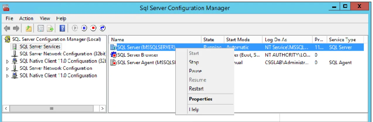
Since we created a WSFC we can enable AlwaysOn High Availability by using the SQL Server Configuration Manager by the followings steps.
1. Start SQL Server Configuration Manager
2. Select the SQL Server Services node under SQL Server Configuration Manager (Local) 3. Select the SQL Server (MSSQLSERVER) service
4. Right-click and select Properties, see Figure 17. 5. Switch to the AlwaysOn High Availability tab
6. The newly created Windows Server Failover Cluster should be listed, eg. PURE-FC1 7. Click the checkbox to Enable AlwaysOn Availability Groups, see Figure 18.
Figure 17. SQL Server Configuration Manager Figure 18. SQL Server properties.
Now that the prerequisites are completed and the servers that will be the secondary replicas have been seeded. We can proceed to create the AlwaysOn Availability Group (AOAG).
Start SQL Server Management Studio and expand the AlwaysOn High Availability node in the Object Explorer. Right-click the Availability Group (AG) folder and choose New Availability Group Wizard…
Step 1. Specify Name
As we are using various AdventureWorks databases the Availability Group will be named AdventureWorks.
Step 2. Select Databases
For this paper four database were created that had dependencies on one another making a logical
grouping that would best demonstrate an Availability Group. Each of these databases can only participate in one AG. Notice that each of the databases meets prerequisites which indicates that full recovery model is set and a full backup was performed.
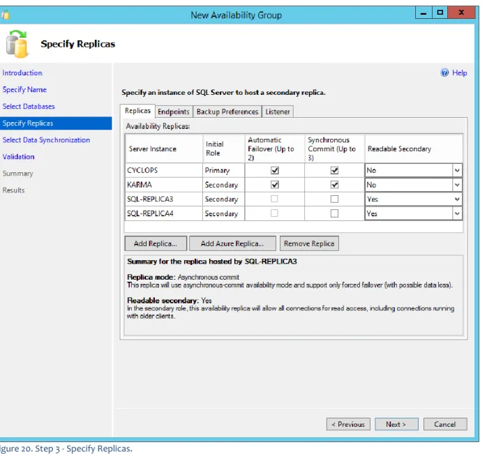
Step 3. Specify Replicas
This step has many different options to choose for the Replicas. For this paper we are keeping the options as simple as possible to not over complicate the deployment. These settings can be revised later. For this AG the two physical servers (CYCLOPS and KARMA) are going to support automatic failover with
synchronous-commit mode and the two virtual instances running on vSphere will serve as readable secondary’s (SQL-REPLICA3 and SQL-REPLICA4).
Figure 20. Step 3 - Specify Replicas.
For Readonly secondary replicas be sure to turn on Auto Update Statistics and Auto Create
Statistics. Readonly database members may have queries run on them that were never executed on the primary replica therefore if the query optimizer deems it necessary to update statistics it cannot because the database is readonly. By turning on these features the optimizer can perform its job.
SQL-REPLICA3 and SQL-REPLICA4 have been set to be Readable Secondary. Making this selection in the wizard will not complete the setup for these servers. ReadOnly Routing (RoR) needs to be completed either using T-SQL or PowerShell, see Appendix II. SQL-REPLICA3 and SQL-REPLICA4 have their replica mode set to asynchronous-mode (not checked) as shown in Figure 20.
The Endpoints tab shows the different endpoint URLs and port information that allows the primary (CYCLOPS) to talk to each of the replicas.
To test if Endpoints will be accessible use any telnet client and use the addresses from the Endpoint URL to test connectivity. This will ensure that there will not be any Firewall and Port issues.
If you require a different endpoint port other than 5022 this should be changed now as once the Availability Group is created these cannot be changed.
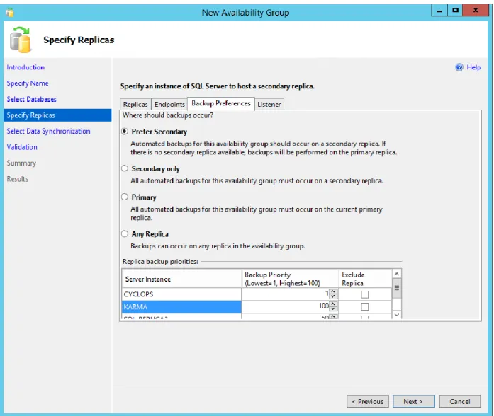
The Backup Preferences tab is one of the more interesting configurations for AGs that allows a secondary replica to be used for backup operations. This allows the primary replica to have any backup operations offloaded. This was a short coming in earlier versions of SQL Server when using database mirroring as mirror servers could not be used for backups. This is one feature that should convince many DBAs to implement Availability Groups. Even though we will not be performing any backup operations we will keep the Prefer Secondary option selected.
Figure 22. Step 3 - Backup Preferences.
Finally the Listener tab is where we can create a new virtual network name (VNN) that allows clients to use for connections to the active primary replica. For this paper creating a Listener is out of scope.
Step 4. Select Initial Data Synchronization
Previously we seeded all of our secondary replicas using the Pure Storage FlashRecover Snapshots of the SQL Server full and transaction log backup/restore process. So the option that we will choose is Join which will join all of the secondary replicas and the restored databases on those servers to the AdventureWorks Availability Group.
Figure 23. Select Initial Data Synchronization (Join).
Step 5. Validation
This step allows you to verify all of the settings made before completing the wizard.
Step 6. Summary
The final step in the New Availability Group Wizard has a very handy feature in the lower right-hand corner,
later time to create other groups or to learn the T-SQL involved in perform these actions from within SQL Server Management Studio.
Figure 24. Step 6 - Summary.
The wizard completed with success, Figure 25 shows all the replicas as part of the Availability Group and are synchronized.
Ensure that all data files (.mdf, .ldf and .ndf) files for the databases are in the same location for all servers. In our example we are using A:\AdventureWorks on CYCLOPS so all secondary replicas should also use A:\AdventureWorks. If you decide to use the Full synchronization method vs the FlashRecover Snapshot method all of the secondary replica file structures must be in place otherwise synchronization cannot be performed by the AlwaysOn Availability Group wizard.
The disaster recovery site in this configuration is used as a recovery site if the primary site has issues or is unavailable. The disaster recovery configuration will use Windows Server Failover Cluster and a highly-available Hyper-V cluster as the core infrastructure providing hyper-visor and virtualized SQL Server services. There are some configurations that are assumed to be completed prior to starting the step-by-step guides provide below.
Assumptions:
1. One Pure Storage FlashArray FA-405 has been installed and configured.
2. Two physical servers have been installed and configured for a Windows Server 2012 R2 Failover Cluster.
3. Two physical servers have been connected through a SAN and networking fabric.
The Disaster Recovery Site setup section describes step-by-step how to configure all of the components for a highly available Microsoft Hyper-V cluster. The following tasks are what we will be performing:
Creating Host Groups and adding Hosts on the Pure Storage FA-405.
Create a Microsoft Windows Server Failover Cluster with a Clustered Shared Volume (CSV).
Create and test a highly available Microsoft Hyper-V failover cluster.
Add Pass-through Disk resources to the Windows Server Failover Cluster to be used by Microsoft SQL Server 2014 Stand-alone.
Setup Pure Storage FlashRecover Replication between the disaster recovery site (FA-405) to the primary site (FA-420) and create all the required Protection Groups.
Live migrate the newly created highly available SQL Server 2014 virtual machine with Pass-through Disks between failover cluster nodes.
Get ready because we are going to be diving into some serious Windows PowerShell work and one heck of a fun step-by-step in and of itself!
Before we can begin deploying any virtual machines or databases the Pure Storage FA-405 needs to be setup with Host Groups and Hosts. The steps in this section makes the assumption that the hardware requirements in the Configuration Overview are the same or similar in your environment. If your setup does not meet those requirements modifications will need to be made in order to follow the steps. Assuming that the physical hosts are connected to the array and configured as in Figure 26 we can create the Host Group that will manage the Microsoft Hyper-V failover cluster.
If your physical hosts are only physically connected to the Pure Storage FlashArray it is possible to use the Pure Storage PowerShell Toolkit 2.0 to create the hosts and their ports (Fibre Channel of iSCSI) using the New-PfaHost cmdlet. This is out of scope for this paper.
Figure 26. Pure Storage FA-405 host connections.
As shown in Figure 26 there are two physical hosts connected to the array. With that information we can create the Host Group and add the existing Hosts.
Import-Module PureStoragePowerShell
$PSToken = Get-PfaApiToken -FlashArray MSFT-PURE2 -Username pureuser -Password pureuser $PSSession = Connect-PfaController -FlashArray MSFT-PURE2 -API_Token $PSToken.api_token New-PfaHostGroup -FlashArray MSFT-PURE2 -Name HYPERV-CLUSTER `
-HostList MSFT-HYPERV-1,MSFT-HYPERV-2 -Session $PSSession
After running the PowerShell the new Host Group and Hosts are created and connected as shown in Figure 27.
Figure 27. Host Group and Hosts connected.
Final step is to check that the replication connection between the Pure Storage FA-420 and FA-405. You can check from either the Web Management GUI or PowerShell, Figure 28 and Figure 29 respectively. This replication connection is what will be used on the disaster recovery side to receive the replicated SQL Server database from the Primary Sites AlwaysOn Availability Group.
Figure 28. Connected Arrays.
Import-Module PureStoragePowerShell
$PSToken = Get-PfaApiToken -FlashArray MSFT-PURE2 -Username pureuser -Password pureuser $PSSession = Connect-PfaController -FlashArray MSFT-PURE2 -API_Token $PSToken.api_token Get-PfaConnection -FlashArray MSFT-PURE2 -Session $PSSession
That’s all that is required for us to now begin deploying all of the components to create a highly available Microsoft Hyper-V cluster with Microsoft SQL Server 2014. Now the fun begins!
In the disaster recovery environment we have created a Windows Server Failover Cluster (WSFC) with support for a highly available Microsoft Hyper-V virtual machine. Below are the basic steps to configure the WSFC and the Hyper-V role once the physical hosts have been setup with Windows Server 2012 R2, updates and networking. The WSFC provides a high degree of local server resiliency and automated local failover for both the physical hosts and the virtual machine.
In the test environment the two nodes of the cluster are named MSFT-HYPERV-1 and MSFT-HYPERV-2, from either node you can add the Windows features by using the -ComputerName parameter. Then it is not necessary to log into both nodes individually.
Add required Windows Server Failover Clustering features to each node. Refer to Figure 7 in the primary site setup section to see what these features will look like after installing.
Add-WindowsFeature -Name Failover-Clustering -ComputerName MSFT-HYPERV-1 Add-WindowsFeature -Name RSAT-Clustering-Mgmt -ComputerName MSFT-HYPERV-1 Add-WindowsFeature -Name RSAT-Clustering-PowerShell -ComputerName MSFT-HYPERV-1 Add-WindowsFeature -Name RSAT-Clustering-AutomationServer -ComputerName MSFT-HYPERV-1 Add-WindowsFeature -Name RSAT-Clustering-CmdInterface -ComputerName MSFT-HYPERV-1 Add-WindowsFeature -Name Failover-Clustering -ComputerName MSFT-HYPERV-2
Add-WindowsFeature -Name RSAT-Clustering-Mgmt -ComputerName MSFT-HYPERV-2 Add-WindowsFeature -Name RSAT-Clustering-PowerShell -ComputerName MSFT-HYPERV-2 Add-WindowsFeature -Name RSAT-Clustering-AutomationServer -ComputerName MSFT-HYPERV-2 Add-WindowsFeature -Name RSAT-Clustering-CmdInterface -ComputerName MSFT-HYPERV-2 Add required Windows Server Hyper-V features to both node of the Windows Server cluster
Add-WindowsFeature -Name RSAT-Hyper-V-Tools -ComputerName MSFT-HYPERV-1 Add-WindowsFeature -Name RSAT-Hyper-V-Tools -ComputerName MSFT-HYPERV-2 Add-WindowsFeature -Name Hyper-V-Tools -ComputerName MSFT-HYPERV-1 Add-WindowsFeature -Name Hyper-V-Tools -ComputerName MSFT-HYPERV-2 Add-WindowsFeature -Name Hyper-V-PowerShell -ComputerName MSFT-HYPERV-1 Add-WindowsFeature -Name Hyper-V-PowerShell -ComputerName MSFT-HYPERV-2
Run these last two commands with the –Restart flag so that the Windows Servers are restarted to complete the setup of Hyper-V. Be sure to run the –Restart on the remote node first then on the working node.
Add-WindowsFeature -Name Hyper-V -ComputerName MSFT-HYPERV-1 -Restart
Figure 30 shows the status of both nodes before restarting.
Figure 30. Installing Windows Server Hyper-V role and features.
Each of the physical hosts now have all of the required Windows roles and features to begin creating the cluster. Before we create the cluster, a Clustered Shared Volume needs to be setup which is what will be covered in the next section.
Using the Pure Storage PowerShell Toolkit 2.0 we will create one (1) new volume that will be used as a Cluster Shared Volume (CSV). The below script will connect to the Pure Storage FlashArray, create a new 500GB volume named HYPERV-CSV and connect that volume to the Host Group named HYPERV-CLUSTER that we created in the Pure Storage FA-405 section. Once everything has been created and connections have completed each of the nodes (MSFT-HYPERV-1 and -2) will be automatically rescanned for the newly attached volume (Register-PfaHostVolumes). This final step of rescanning the hosts can also be achieved by using the Disk Management tool in Windows Server 2012 R2.
Import-Module PureStoragePowerShell
$PSToken = Get-PfaApiToken -FlashArray MSFT-PURE2 -Username pureuser -Password pureuser $PSSession = Connect-PfaController -FlashArray MSFT-PURE2 -API_Token $PSToken.api_token New-PfaVolume -FlashArray MSFT-PURE2 -Name HYPERV-CSV -Size 500G -Session $PSSession Connect-PfaHostGroup -FlashArray MSFT-PURE2 -Name HYPERV-CLUSTER `
-Volume HYPERV-CSV -Session $PSSession
Register-PfaHostVolumes -Computername MSFT-HYPERV-1 Register-PfaHostVolumes -Computername MSFT-HYPERV-2
See Figure 31 which illustrates what the Pure Storage FlashArray will look like after running the above
Figure 31. Newly created 500GB HYPERV-CSV volume.
After the above Windows PowerShell has been run access each of the nodes and open Disk Management which will show the newly added Pure Storage volume. They are still in a Not Initialized state. In Figure 32 the newly added volume is called Disk 4.
It is important to leave this new volume in the current state as we will configure this to be used as the Clustered Shared Volume (CSV). On to creating the Windows Server Failover Cluster.
Before we configure the CSV we need to create a new WSFC just as we did on the Primary Site. When creating the new cluster the –NoStorage option is used to ignore shared storage at the moment as we will
do that a bit later.
New-Cluster -Name PURE-FC2 -Node MSFT-HYPERV-1, MSFT-HYPERV-2 `
-StaticAddress 10.21.8.54 -NoStorage
Figure 33. Newly created PURE-FC2 failover cluster.
Now we need to add disks to the newly created PURE-FC2 cluster. The newly added volume, CSV, can be located using the below PowerShell.
Get-Disk | Where-Object `
The test system is a clean system without any existing volumes so the query returns only a single volume at this time. If you are following along in your own environment to recreate this scenario it may require modification to some of the scripts to ensure the proper volumes are being used. Figure 34 shows the output from the Get-Disk operation.
Figure 34. Retrieving the CSV volume using Get-Disk
There are numerous steps involved in adding a volume, initialization, creating a new partition, formatting the volume and then adding the new volume as cluster resources. The following PowerShell handles all of the steps involved.
$CSV = Get-Disk | Where-Object { $_.FriendlyName -like "PURE FlashArray*" -And ` $_.PartitionStyle -eq "RAW" }
Initialize-Disk -Number $CSV.Number -PartitionStyle GPT
$CSVFS = New-Partition -DiskNumber $CSV.Number -UseMaximumSize -AssignDriveLetter
Format-Volume -DriveLetter $CSVFS.DriveLetter -FileSystem NTFS `
-NewFileSystemLabel "HYPERV-CSV" -Force -Confirm:$False Get-ClusterAvailableDisk | Add-ClusterDisk
Get-ClusterResource *Disk* | Add-ClusterSharedVolume
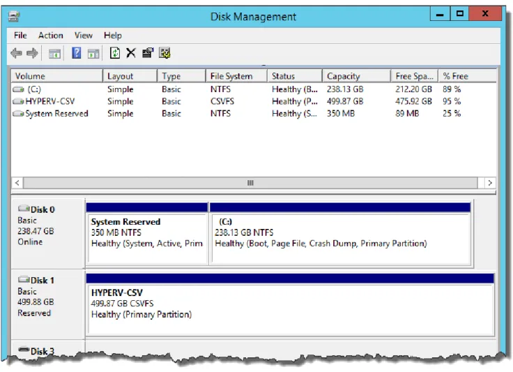
Once the CSV volume has been added to the PURE-FC2 cluster it will be shown as follows in the Failover Cluster Manager (Figure 35) and Disk Management (Figure 36) user interfaces.
Figure 36. Disk Management showing CSV volume with File System of CSVFS.
Before continuing let’s take a moment to review what we have completed so far:
Added required roles and features for Windows Server Failover Clustering and Hyper-V.
Created a new volume for the CSV and connected that to the Host Group for the Hyper-V cluster.
Created a new Windows Server Failover Cluster named PURE-FC2.
Add the new volume, CSV, to Failover Cluster owner node, MSFT-HYPERV-1.
Initialized, formatted and added the CSV volume to the PURE-FC2 cluster.
The next steps all focus on configuring and creating the resources needed for a Hyper-V cluster.
Now that all of the components are installed for Hyper-V we can begin configuring the physical hosts, MSFT-HYPERV-1 and -2, to host a highly available Hyper-V failover cluster.
First is to create a new VM virtual switch on both of the nodes. Determine which network adapter to use by querying the physical host. To avoid confusion with the configuration only the network adapters with a Status=Up are retrieved.
Get-Netadapter -CimSession MSFT-HYPERV-2 | Where-Object { $_.Status -eq 'Up' } Get-Netadapter -CimSession MSFT-HYPERV-1 | Where-Object { $_.Status -eq 'Up' } Results:
Figure 37. Get-NetAdapter results.
Now we have the different adapters from MSFT-HYPERV-1 and -2 we can set up the new VM external switches to be used by Hyper-V. In the below example I am using Ethernet and Ethernet 2 from MSFT-HYPERV-1 and -2 respectively.
New-VMSwitch -ComputerName MSFT-HYPERV-1 -Name "My VM External Switch" `
-NetAdapterName "Ethernet" -AllowManagementOS $true `
-Notes "Example for Pure Storage SQL Server AlwaysOn Reference Architecture" New-VMSwitch -ComputerName MSFT-HYPERV-2 -Name "My VM External Switch" `
-NetAdapterName "Ethernet 2" -AllowManagementOS $true `
-Notes "Example for Pure Storage SQL Server AlwaysOn Reference Architecture" Results:
Viewing the Virtual Switch Manager from the Hyper-V Manager shows that the new virtual switch has been created successfully (Figure 39).
Figure 39. MSFT-HYPERV-2 Virtual Switch Manager.
Now we can create the new virtual machine and store it on the clustered shared volume created
previously, HYPERV-CSV. Below are the steps involved in creating a new virtual machine. The PowerShell following these steps will take care of all the heavy lifting.
1. Create the VHDX file 2. Create the VM
4. Add the VM clustering role 5. Start the VMs
For this paper I am using SQL-DR1 as the name of the new virtual machine, but any of the variables can be altered to use any names or locations. I created a basic ForEach loop so you could create as many VMs
dynamically as you wanted. For this paper we are only creating one VM to be used for SQL Server Stand-alone instance. ForEach ($VM in 1..1) { $VNName = "SQL-DR" $CSVPath = "C:\ClusterStorage\Volume1" $VHDXPath = "C:\ClusterStorage\Volume1\SQL-DR$VM.VHDX" $ISOPath = "\\10.21.8.5\iso\Windows\en_windows_server_2012_r2_x64_dvd_2707946.iso" $VMSwitch = "My VM External Switch"
New-VHD -Path $VHDXPath -Dynamic -SizeBytes 75GB
New-VM -Name $VNName$VM -Path $CSVPath -Memory 16GB –SwitchName $VMSwitch `
–BootDevice CD -VHDPath $VHDXPath
Add-VMDvdDrive -VMName $VNName$VM –Path $ISOPath Set-VM –Name $VNName$VM –AutomaticStartAction Nothing Add-ClusterVirtualMachineRole -VirtualMachine $VNName$VM Start-VM -Name $VNName$VM
}
Figure 40 shows results for creating the SQL-DR1 virtual machine.
Figure 41 shows the newly created virtual machine from Failover Cluster Manager. Once we add the Cluster Virtual Machine Role all management of the VM should happen through the Failover Cluster Manager.
Figure 41. Failover Cluster Manager view of newly created virtual machines.
At this point because we created a new virtual machine from scratch the normal process for installing the operating system should be followed. Once the operating system has been configured the next step is to test live migration and unplanned failure.
There are several different methods to move a clustered virtual machine:
Live migration – Move ownership of the clustered virtual machine to another node without pausing the role.
Quick migration – Pause the virtual machine, save state, move the role to another node, and start the virtual machine on the other node.
Storage migration – Move only the virtual machine data to other clustered storage.
For this paper we are using Live Migration. Start a Windows PowerShell session if not already started and use the following script to Live Migrate the virtual machine.
Move-ClusterVirtualMachineRole -Name "SQL-DR1" –Node MSFT-HYPERV-2 Figure 42 illustrates the Live Migration taking place.
Figure 42. Live Migration of SQL-DR1 virtual machine to MSFT-HYPERV-2.
Figure 43 shows a successful Live Migration with SQL-DR1 now being owned by MSFT-HYPERV-2.
Figure 43. Successful Live Migration.
Now that SQL-Dr1 is running on MSFT-HYPERV-2 it is possible to test an unplanned failover by suddenly stopping the HYPERV-2 cluster node. This will force the SQL-DR1 VM to migrate back to MSFT-HYPERV-1.
This stopped the 2 node suddenly and migrated the SQL-DR1 virtual machine MSFT-HYPERV-1 node. Once this test completes successfully the MSFT-HYPERV-2 node can be restarted.
Start-ClusterNode -Name MSFT-HYPERV-2
The final step is to configure the virtual machine with network parameters. Warning: the PowerShell involved in this step is an advanced topic. Play close attention to the (tick `) marks in the below script. $VMName = "SQL-DR1"
$Msvm_VirtualSystemManagementService = Get-WmiObject `
-Namespace root\virtualization\v2 -Class Msvm_VirtualSystemManagementService $Msvm_ComputerSystem = Get-WmiObject -Namespace root\virtualization\v2 `
-Class Msvm_ComputerSystem -Filter "ElementName='$VMName'" $Msvm_VirtualSystemSettingData = `
($Msvm_ComputerSystem.GetRelated("Msvm_VirtualSystemSettingData", `
"Msvm_SettingsDefineState", $null, $null, "SettingData", "ManagedElement", ` $false, $null) | % {$_}) $Msvm_SyntheticEthernetPortSettingData = ` $Msvm_VirtualSystemSettingData.GetRelated("Msvm_SyntheticEthernetPortSettingData") ` $Msvm_GuestNetworkAdapterConfiguration = ` ($Msvm_SyntheticEthernetPortSettingData.GetRelated( ` "Msvm_GuestNetworkAdapterConfiguration", "Msvm_SettingDataComponent", ` $null, $null, "PartComponent", "GroupComponent", $false, $null) | % {$_}) $Msvm_GuestNetworkAdapterConfiguration.DHCPEnabled = $false
$Msvm_GuestNetworkAdapterConfiguration.IPAddresses = @("10.21.8.57") $Msvm_GuestNetworkAdapterConfiguration.Subnets = @("255.255.248.0") $Msvm_GuestNetworkAdapterConfiguration.DefaultGateways = @("10.21.8.1") $Msvm_GuestNetworkAdapterConfiguration.DNSServers = @("10.21.8.5")
$Msvm_VirtualSystemManagementService.SetGuestNetworkAdapterConfiguration( `
$Msvm_ComputerSystem.Path, $Msvm_GuestNetworkAdapterConfiguration.GetText(1))
It is not necessary to use the above method to configure the network for the virtual machine. The old fashion method of starting the virtual machine and manually configuring the adapter settings
through Network and Sharing Center can be used instead.
Now we have connectivity and the final step is to add the SQL-DR1 virtual machine to a domain. Basic setup of a Windows Server 2012 R2 machine creates a random server name which we can change and add to a domain. Log into the new virtual machine with the credentials created during Windows Server 2012 R2 setup. Either use Server Manager or Windows PowerShell to add the computer to the domain and set a new name for the machine if not already completed during setup. Below is the PowerShell that when run from the virtual machine will add it to the <DomainName> as <ServerName> of your choosing you will need domain administrator or equivalent credentials to add the virtual machine.
Add-Computer -DomainName <DomainName> -Credential (Get-Credential)
Rename-Computer -ComputerName $env:COMPUTERNAME -DomainCredential (Get-Credential) `
-NewName SQL-DR1 -Restart
While the virtual machine is restarting let’s take a moment to review where we are with respect to setting up the disaster recovery site of this reference architecture.
1. Two physical hosts have been configured with Windows Server 2012 R2.
2. Both physical hosts have been configured with Hyper-V and Failover Clustering. 3. Hosts, Host Group and Volumes have been configured on the Pure Storage FA-405.
4. A new volume to be used as the Clustered Shared Volume has been created on the Pure Storage FlashArray.
5. The Clustered Shared Volume has been configured to be used by the Failover Cluster. 6. Hyper-V has been configured with a new Virtual Switch on both Failover Cluster nodes.
7. One new virtual machine has been created on the owner node, MSFT-HYPERV-1, of the Clustered Shared Volume.
8. Installed Windows Server 2012 R2 on the newly created virtual machine. This was a manual step. 9. Tested Live Migration and an unplanned failover.
10. Injected the virtual machine with network configuration information.
Now that the core infrastructure is in place and tested we can be sure that our Windows Server 2012 R2 virtual machine is working as a highly available Hyper-V failover cluster. Now we can take the steps necessary to prepare to install and configure Microsoft SQL Server 2014.
Before we start installing SQL Server we need to create some new volumes on the Pure Storage FlashArray that can be used as Pass-Through Disks for the System data files (master, model, msdb) and tempdb. We will use these Pass-Through Disks with the highly available Hyper-V VM so we can continue to support failover and live migration operations.
The volumes we create on the Pure Storage FlashArray need to be connected to the Host Group, HYPERV-CLUSTER, so the volumes will be available to all nodes of the failover cluster; do not confuse this with a cluster shared volume.
Import-Module PureStoragePowerShell
$PSToken = Get-PfaApiToken -FlashArray MSFT-PURE2 -Username pureuser -Password pureuser $PSSession = Connect-PfaController -FlashArray MSFT-PURE2 -API_Token $PSToken.api_token New-PfaVolume -FlashArray MSFT-PURE2 -Name SQLVM-SYS -Size 100G -Session $PSSession New-PfaVolume -FlashArray MSFT-PURE2 -Name SQLVM-TEMPDB -Size 1T -Session $PSSession Connect-PfaHostGroup -FlashArray MSFT-PURE2 -Name HYPERV-CLUSTER `
-Volume SQLVM-SYS -Session $PSSession
Connect-PfaHostGroup -FlashArray MSFT-PURE2 -Name HYPERV-CLUSTER ` -Volume SQLVM-TEMPDB -Session $PSSession
Figure 44 shows the Pure Storage Web Management GUI and the newly created volumes attached to the HYPERV-CLUSTER Host Group.
Figure 44. SQL Server volumes SQLVM-SYS and SQLVM-TEMPDB.
The next step is to make these volumes available to the Hyper-V failover cluster so they can be shared between the nodes of the cluster for failover. We will be configuring these new volumes on MSFT-HYPERV-1 so we need to scan the bus.
Register-PfaHostVolumes -Computername MSFT-HYPERV-1
Figure 45 shows the new volumes list in Disk Management of the MSFT-HYPERV-1 node.
Figure 45. SQLVM-SYS and SQLVM-TEMPDB shown in Windows Server Disk Management.
The next set of steps are very important in order to create the Pass-Through Disks properly for use with highly available Hyper-V VM. The lab system that we are using for this paper is clean and understanding that your environment may not be, you should query the Windows server for the volumes before making any changes.
Get-Disk | Where-Object { $_.FriendlyName -like "PURE FlashArray*" }
Figure 46 shows the results of the Get-Disk cmdlet and there are two volumes in RAW format which are the new volumes we added, Number 4 and 5.
Figure 46. Get-Disk results.
Since these volumes have never been presented to the Windows Server Failover Cluster before we need to bring them online. Additionally they need to be initialized in order to obtain a disk signature so that Windows can identify them.
Set-Disk -Number 4 -IsOffline $false Set-Disk -Number 5 -IsOffline $false Initialize-Disk -Number 4
Initialize-Disk -Number 5
In order for these volumes to be used as Pass-Through Disks we now need to take the volumes offline as they will be owned by the failover cluster. There is no need to partition the volumes as the Hyper-V VMs, SQL-DR1 and SQL-DR2, will handle that task.
Set-Disk -Number 4 -IsOffline $true Set-Disk -Number 5 -IsOffline $true
Now we can add these volumes as cluster resources to the Windows Server Failover Cluster. Running Get-ClusterAvailableDisk will show that these two new volumes are available.
Get-ClusterAvailableDisk
Figure 47 shows both Disk Number 4 and 5 are available as Cluster Disk 2 and 3.
Figure 47. Results from Get-ClusterAvailableDisk.
Now the two disks can be added to the cluster. Add-ClusterDisk