Sharif University of Technology
Scientia IranicaTransactions B: Mechanical Engineering www.scientiairanica.com
The size-dependent electromechanical instability of
double-sided and paddle-type actuators in centrifugal
and Casimir force elds
J. Mokhtari
a, M. Farahani
b, A. Kanani
c, R. Rach
d, M. Keivani
eand M. Abadyan
f; a. Department of Mathematics, Isfahan (Khorasgan) Branch, Islamic Azad University, Isfahan, Iran.b. Department of Aerospace Engineering, Sharif University of Technology, Tehran, P.O. Box 11365-11155, Iran.
c. Ionizing and Non-Ionizing Radiation Protection Research Center, Paramedical Sciences School, Shiraz University of Medical Sciences, Shiraz, Iran.
d. The George Adomian Center for Applied Mathematics, 316 South Maple Street, Hartford, Michigan 49057-1225, USA. e. Department of Radiology, Shahrekord University of Medical Sciences, Shahrekord, Iran.
f. Department of Engineering, Shahrekord Branch, Islamic Azad University, Shahrekord, Iran. Received 22 July 2015; received in revised form 15 December 2015; accepted 28 June 2016
KEYWORDS Double-sided nanoactuator; Paddle-type nanoactuator; Angular speed; Cylindrical nanowire; Size phenomenon; Casimir regime.
Abstract.The present research is devoted to theoretical study of the pull-in performance of double-sided and paddle-type NEMS actuators fabricated from cylindrical nanowire operating in the Casimir regime and in the presence of the centrifugal force. D'Alembert's principle was used to transform the angular velocity into an equivalent static, centrifugal force. Using the couple stress theory, the constitutive equations of the actuators were derived. The equivalent boundary condition technique was applied to obtain the governing equation of the paddle-type actuator. Three distinct approaches, the Duan-Adomian Method (DAM), Finite Dierence Method (FDM), and Lumped Parameter Model (LPM), were applied to solve the equation of motion of these two actuators. This study demonstrates the inuence of various parameters, i.e., the Casimir force, geometric characteristics, and the angular speed, on the pull-in performance.
© 2017 Sharif University of Technology. All rights reserved.
1. Introduction
A double-sided NEMS is constructed from a movable cantilever suspended between two actuating xed elec-trodes. The double-sided NEMS has recently attracted much attention due to its promising electromechanical performance such as low power consumption, quick response, etc. [1,2]. The double-sided driven scheme has been proposed for the actuation of gyroscopes and memory elements [3,4]. Electrostatic resonators
*. Corresponding author. Tel.: +98 3813337637 E-mail addresses: javadmokhtari67@yahoo.com (J. Mokhtari); mfarahani@sharif.edu, (M. Farahani); en.a.kanani@gmail.com (A. Kanani); tapstrike@triton.net (R. Rach); abadyan@yahoo.com (M. Abadyan)
possess high stability and resolution based on the double-sided NEMS [3]. These double-sided systems are also attractive for detecting ultra-small mass and sensing mechanical forces [3]. Fu et al. [2] used the energy balance approach for modeling the oscillation of double-sided microbridges. Ke studied the instability of a double-sided resonator [3]. Khan and Akbarzade employed analytical methods to study the oscillation of a driven double-sided miniature resonator [5]. More useful information about double-sided NEMS can be found in [6,7].
The cantilever beam with a rigid plate attached to its free end is called a paddle-type conguration. Recently, several studies have investigated the paddle-type MEMS/NEMS as sensors [8], actuators [9], res-onators [10], capacitors, and lters [8-11]. Qian et
al. [12] developed a capacitive paddle-type NEMS switch fabricated from silicon nanowires. Zhang et al. [10] examined the use of paddle-type resonators for thermal sensing. Tong et al. [11] showed that the paddle-type conguration can eliminate internal stress distribution. Ahmad et al. [13] designed a paddle-type sensor using the COVENTOR software. Other researchers [14,15] investigated a micro-generator con-sisting of a silicon paddle-type element. Ouakad [8] studied the eect of shock loading on performance of a paddle-type gas sensor. More information about paddle-type NEMS is available in the literature [16,17]. With recent demands for advanced devices, MEMS/NEMS capacitive sensors are increasingly used in developing measurement systems. Measurement of the angular speed is important in rotary systems [18]. There are many promising applications, such as the fault detection of roller bearings [19], balancing rotat-ing equipment [20], measurement of high-speed spindle errors [21], uidic centrifuges [22], turbomachinerry, etc. In these applications, the presence of the cen-trifugal force plays a major role in determining the electromechanical response of these NEMS sensors. Recently, the paddle-type and double-sided sensors have been considered as angular speed sensors and accelerometers [23-25]. Herein, the eect of the cen-trifugal force is incorporated into the pull-in instability models of paddle-type and double-sided sensors.
For precise modeling of the pull-in performance of the aforementioned nanostructures, the Casimir force should be included in the model [26-28]. Almost all previous investigations in this area have been devoted to those devices with planar congurations, while only few investigations have considered it in actuators which are fabricated from nanowires with cylindrical geometries [29,30]. A simplistic approach for determining the vacuum uctuations for compound shapes is the Proximity Force Approximation (PFA) [31,32]. Herein, the PFA is employed to demonstrate the eect of the Casimir force on the physical response of the paddle-type and double-sided NEMS. In addition to the Casimir attraction, the size eect is another crucial phenomenon that should be incorporated into the theoretical model. Experiments have shown a hard-ening trend in the elastic response of some nanowires as the structure dimensions approach the material length scale [33,34]. This size eect cannot be modeled by classic continuum mechanics. In order to overcome this shortcoming, the classical theories, such as non-local elasticity [35], Couple Stress Theory (CST) [36-38], strain gradient theory [39], modied couple stress theory [40], etc., have been developed to consider the size eect on theoretical continuum models. Despite other size-dependent theories, limited research has been conducted on modeling the ultra-small structures using the CST [41-43].
This work presents the inuence of the centrifugal force, Casimir eect, and size phenomenon on the elec-tromechanical instability of paddle-type and double-sided nanoactuators. The size eect is modeled using the CST in conjunction with the Euler-Bernoulli beam model. Three distinct solution methods, i.e. the Duan-Adomian Method (DAM), Finite Dierence Method (FDM), and Lumped Parameter Model (LPM), are employed to solve the nonlinear governing equations. 2. Theory
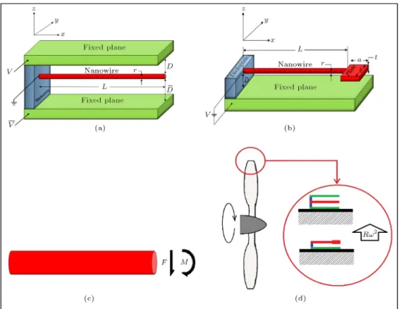
Figure 1(a) shows the schematic diagram of the typical double-sided NEMS actuator. The voltage dierence and initial gap between the movable electrode and upper plane are V and D, respectively. The potential dierence and initial separation between the nanowire and the lower plane are V and D, respectively. The nanowire of length L and radius r is considered. Figure 1(b) depicts the schematic diagram of a typical paddle-type NEMS which is suspended over the xed plane and deected by applying electrostatic attrac-tion. The voltage between the paddle and the ground planes is V . The nanowire of length L and radius r is considered. The rigid plate has length a, width b, and thickness t.
The internal resultants in an arbitrary cross-section of the nanowire are shown in Figure 1(c), where F and M denote the force and moment at the non-supported end of the nanowire (at x = L), respectively. To obtain the equation of motion of the nanowire in the presence of the centrifugal force (Figure 1(d)), the Hamilton's principle is utilized:
(U V ) = 0; (1)
where denotes the variation symbol, U is the strain energy, and V is the work done by all forces.
2.1. Strain energy
In the CST, the strain energy depends on the rotation gradient as well as the strain [44]. Displacement gra-dient tensor, ui;j, is decomposed into symmetric strain
and skew-symmetric rotation tensors, respectively, as:
ui;j= "ij+ !ij; (2)
where:
"ij= 12(ui;j+ uj;i) = "ji;
!ij =12(ui;j uj;i) = !ji: (3)
The rotation vector is:
i=12eijkuk;j; (4)
Figure 1. (a) The double-sided NEMS. (b) The paddle-type NEMS. (c) Internal resultants in arbitrary wire cross-section. (d) The nanostructure in the presence of the centrifugal force.
ij= j;i=12ejklul;ki: (5)
The strain energy density based on the CST can be expressed as [42,45]:
~u = 12"ij"ij+ "ij"ij+ 2ijij+ 20ijij; (6)
where and are the classic Lame constant and shear modulus, respectively. Moduli and 0 are constants
which correspond to the couple stress eects. The classic symmetric Cauchy stress tensor (ij) and the
couple stress tensor (mij), respectively, can be derived
from Eq. (6) as follows: ij = @"@~u
ij = "mmij+ 2"ij; (7a)
mij =@@~u
ij = 4ij+ 4 0
ji: (7b)
Based on the Euler-Bernoulli beam model, the compo-nents of the displacement are [46]:
uX(X; Y; Z) = Z@w(X)@X ; uY(X; Y; Z) = 0;
uZ(X; Y; Z) = w(X): (8)
By substitution of Eqs. (8) into Eqs. (3), (4), and (7), the following relations for the components of the strain,
stress, gradient of rotation, and couple stress tensors are obtained as follows:
"XX = Z@ 2w
@X2;
"Y Y = "ZZ= "XY = "Y Z= "ZX = 0; (9a)
XX = EZ@ 2w
@X2;
Y Y = ZZ = Y Z= ZX= XY = 0; (9b)
XY = @
2w
@X2;
XX = Y Y = ZZ= Y Z= ZY = ZX
= XZ= Y X = 0; (9c)
mXY = 4@ 2w
@X2; mY X = 40
@2w
@X2;
mXX = mY Y = mZZ = mY Z= mZY = mZX
= mXZ= 0: (9d)
By substituting Eq. (9) into Eq. (6) and integrating over the length of the nanowire, the strain energy is
calculated as follows: U =12
Z L
0 (EeI + 4A)
@2w
@X2
2
dX; (10)
where I and A are the second moment and area of the cross-section of the nanowire, respectively. As shown, the strain energy does not depend on 0. According to
the previous investigation [45], material constant can be redened as:
= l2; (11)
where l is the material length scale parameter. Note that the eect of large deformation is not considered in the model (see Appendix A).
2.2. Work by all forces
The work by all forces is the summation of the work done by the external forces (fext) and the work done
by the internal tractions, i.e. moment (M) and force (F ).
The external forces include the electrostatic and Casimir attractions. The work done by external forces, Vfext, is expressed as:
Vfext =
Z L
0
Z w
0 fextdwdX: (12)
The work done by internal moment, VM, is obtained
as: VM =
Z @w(L) @X
0 M
w(L);@w(L)@X
d@w(L)@X : (13) The work done by internal force, VF, is determined as:
VF =
Z w(L)
0 F
w(L);@w(L)@X
dw(L): (14)
Finally, the overall work done by the aforementioned forces is obtained as:
V =Vfext+ VM + VF =
Z L
0
Z w
0 fextdZdX
+ Z @w(L) @X 0 M w(L);@w(L) @X d@w(L) @X + Z w(L) 0 F
w(L);@w(L)@X
dw(L): (15)
2.3. The governing equation
By substituting Eqs. (10) and (15) into Eq. (1), we can obtain the following equation for the variation as follows:
(V U)=
Z L 0
EeI +4Al2 @ 4w
@X4 fext
wdX EeI + 4Al2 @
3w
@X3w
L
0
+ EeI + 4Al2 @ 2w @X2 @w @X L 0 M @w @X
L F wjL= 0: (16)
Hence, the governing equation for the equilibrium of the nanowire is derived from Eq. (16) as follows:
EeI + 4Al2 d 4w
dX4 = fext; (17a)
subject to the geometric boundary conditions of:
w(0) = 0; dXdw(0) = 0; (17b)
and the natural boundary conditions of: EeI + 4Al2 d
2w
dX2(L) = M;
EeI + 4Al2 d 3w
dX3(L) = F: (17c)
Eqs. (17) in general can be specialized for each NEMS by substituting their respective formulas for fext, M,
and F . This is considered in the following subsections. 2.3.1. The double-sided structure
For the double-sided actuator (Figure 1(a)), fext in
Eq. (17a) can be dened as:
fext= felec1 felec2+ fCas1 fCas2+ fCent; (18)
where felec1 and fCas1 are the electrical and Casimir
attractions between the wire and the upper plane, respectively. felec2 and fCas2 denote the electrical and
Casimir attractions between the wire and the lower plane, respectively. fCent is the centrifugal force.
The electrical force terms in Eqs. (17) can be determined from the capacitive model [47]. The electrostatic energy for a cylindrical conductor parallel to conductive plane (Eelec) is given as follows [48]:
Eelec= "0"rLV 2
arccos h 1 +D r
; (19)
where "0 and V are the permittivity of vacuum and
the imposed DC voltage, respectively. Hence, by dierentiating the electrostatic energy, the electrical
attraction per unit length of cylinder, felec, is derived
from Eq. (19) as follows:
felec=dEdDelec= "0"rV 2
p
(D+2r)(D) arccos h2 1+D r
: (20) By considering the deection of nanowire, felec1 and
felec2 can be derived by replacing D with D1 w and
D2+ w, respectively, in Eq. (20). Note that the eect
of Charge-tip has not been incorporated while it might be important (see Appendix B).
The Casimir force terms in Eq. (17) can be deter-mined using the PFA. Based on the PFA, the Casimir energy for a conductive cylindrical wire parallel to a conductive plane (EPFA) is determined as [31,32]:
EPFA= 3hcL
960 r
r
2D5; (21)
where h = 1:05457 10 34J.s is the reduced Planck's
constant, c = 2:998 108 m/s is the speed of light,
and D is the gap distance between the nanowire and the plane, respectively. Therefore, the Casimir attraction per unit length of cylinder, fCas, is derived
by dierentiating Eq. (21) as follows: fCas= dE
PFA
dD =
3hc
768 r
2r
D7: (22)
Regarding the displacement of the nanowire and replac-ing D with D w in Eq. (22), fCas1 can be derived.
Similarly, fCas2can be obtained by substituting D with
D + w in Eq. (22).
According to D'Alembert's principal, we can transform an angular speed into an equivalent centrifu-gal force. Hence, the contribution of the centrifucentrifu-gal force can be modeled by considering the angular ve-locity of the system. The centrifugal force per unit length of the nanowire, caused by rotation of a rotary machine, is determined as [24,25]:
fCent= r2(R D)!2; (23)
where , R, and ! are the density of the nanowire, the rotary surface radius, and the angular speed of the rotary surface, respectively. For the case of R D, Eq. (22) is reduced to:
fCent= r2R!2: (24)
The boundary conditions for the double-sided actuator at the free end are dened as traction free (F = M = 0). Hence, Eq. (17c) is reduced to the following relations:
d2w
dX2(L) =
d3w
dX3(L) = 0: (25)
For the double-sided actuator, by using Eqs. (18), (20), (22), and (24), the governing equation for Eq. (17) can nally be written as:
(1 + )ddx4w^4
=p
(1 ^w) [1+k (1 ^w)] arccos h2(1+2k (1 ^w))
p
(+ ^w) [1+k (+ ^w)] arccos h2(1+2k (+ ^w))
+
(1 w)^ 72
( + ^w)72 + !; (26a)
^
w(0) = d ^w
dx(0); (26b)
d2w^
dx2(1) =
d3w^
dx3(1) = 0; (26c)
where the dimensionless parameters in Eq. (24) are dened as follows:
x = XL; w =^ Dw; = DD; = VV 2
; k = 2rD; = 4AlE 2
eI =
16l2
Eer2;
! = rE2L4R!2
eID ; =
hc3r1 2L4
384p2EeID92;
= p"0"rV2L4 2r1
2EeID32: (27)
2.3.2. The paddle-type structure
For the paddle-type actuator, by replacing D with D w in Eqs. (20) and (22), fextcan be dened as follows:
fext=felec+ fCas+ fCent
=p "0"rV2
(D w + 2r)(D w) arccos h2 1 +D w r
+3hc
768 s
2r
(D w)7 + r2R!2: (28)
To obtain the appropriate boundary conditions, the distributed forces acting on the plate are replaced with an equivalent concentrated force acting at distance x from the nanowire tip (the force center). The value of x is determined from x = M=F relation. Based on this approach, the boundary conditions at the non-supported end of the nanowire can be obtained as follows:
EeI + 4Al2 d 2w
dX2(L)
="02"r abV2x
(D w(L) xw0(L))2
+ 2~cabx
240 (D w(L) xw0(L))4
+a2btR!2 2; (29a)
EeI + 4Al2 d 3w
dX3(L)
= "02"r abV2
(D w(L) xw0(L))2
2~cab
240 (D w(L) xw0(L))4
abtR!2: (29b)
By substituting Eq. (28) into Eq. (17) and using the dimensionless parameters in Eq. (27), the non-dimensional governing equation of the paddle-type actuator is:
(1 + )ddx4w^4
=p
(1 ^w) [1+k (1 ^w)] arccos h2(1+2k(1 ^w))
+
(1 w)^ 72 + !; (30a)
^
w(0) = ^w0(0) = 0; (30b)
(1+)ddx2w^2(1)=# "
2k3
2(1 ^w(1) ^w0(1))2
+ 16
5k1
2(1 w(1) ^^ w0(1))4 +
2! #
; (30c)
(1+)ddx3w^3(1)= # "
2k32 (1 ^w(1) ^w0(1))2
+ 16
5k1
2(1 w(1) ^^ w0(1))4 + 4!
#
; (30d) where the dimensionless parameters are dened as follows:
#=2rLab ; =ax;
=DL; =Da: (31)
3. Solution methods
3.1. Duan-Adomian Method (DAM)
Recently, Duan has developed a fast decomposition algorithm [49] that is employed in conjunction with the Adomian decomposition method [50] for solving boundary value problems. To analytically solve the governing equations (Eqs. (26) and (30)), we consider the following general fourth-order dierential equation with the nonlinearity f(x; ^w) as:
d4w(x)^
dx4 = f (x; ^w(x)) ; (32a)
^
w(0) = C1; w^0(0) = C2: (32b)
The solution of Eq. (32a) can be determined as: ^
w(x) =
1
X
n=0
^
wn(x) = C1+ C2x
+ 1
2!C3x2+ 1 3!C4x3 +
x
Z
0 x
Z
0 x
Z
0 x
Z
0
"1 X
n=0
fn(x)
#!
dxdxdxdx; (33) where C1, C2, C3, and C4 are the constants of
integration. Note that in the case of Eq. (17), the values of C1 and C2 are both zero. Based on the
DAM, polynomials fn(x) can be determined from the
following relation [49,51]: fn=
n
X
k=1
Ck
nh(k)( ^w0) ; (34)
where terms h(k) and Ck
n are determined from the
following algorithm [51]:
Ck n =
8 > > > < > > > : ^
wn; k =1; n1;
1 n
n kP
j=0(j + 1) ^wj+1C k 1
n 1 j; 2 k n; (35a)
h(k)= @kf
@ ^wk
0; k 1: (35b)
Now, by using Eqs. (33) and (34), the solution to Eq. (26) can be calculated as follows:
^
w =2!1C3x2+3!1C4x3
+4!(1+)1 "
p
1+k arccos h2(1+2k)
p
(1+k) arccos h2(1+2k)+
p
7+ !
# x4
+7!(1 + )1 "
2pk
(1 + k) arccos h3(1 + 2k)
+ 2
p k
(1 + k) arccos h3(1 + 2k)
+2(1 + k)3=2(1 + 2k)arccos h2(1 + 2k)
+ (1 + 2k)
2p3(1 + k)3=2arccos h2(1 + 2k)+
7 2
+ 7
2p9
#
7C3x6+ C4x7+ : (36)
Similarly, the solution to Eq. (30) can be determined as follows:
^ w =1
2!C3x2+ 1 3!C3x3
+ 1
4!(1+)
p
1+k arccos h2(1+2k)++ !
x4
+7!(1 + )1 "
2pk
(1 + k) arccos h3(1 + 2k)
+2(1 + k)3=2(1 + 2k)arccos h2(1 + 2k) +72
#
7C3x6+ C4x7+ :
(37) Finally, constants C3and C4are determined by
bound-ary conditions (Eqs. (26b) and (26c)) and (Eqs. (30b), (30c) and (30d)) for the double-sided and paddle-type nanostructures, respectively.
3.2. FDM
According to the nite dierence method, the domain is discretized into n equal segments located between (n + 1) nodes. For each segment, dierential equations (Eq. 17(a)) are discretized as follows:
^
wi 2 4 ^wi 1+ 6 ^wi 4 ^wi+1+ ^wi+2
x4 = Fi: (38)
In the above equation, x represents the grid spacing, ^
wi represents the deection of the ith grid, and Fi is:
Fi=
1 1+
p
(1 ^wi)[1+k (1 ^wi)] arccos h2(1+2k (1 ^wi)) 1
1+
p
(+ ^wi) [1+k(+ ^wi)] arccos h2(1+2k (+ ^wi))
+ 1+1 (1 ^wi)
7 2
1 1+
(+ ^wi)
7
2+ !; i=1; 2; ; N: (39)
For the paddle-type actuator, we have Eq. (40) as shown in Box I.
By imposing Eq. (38) on all segments and using the boundary conditions, the following system of alge-braic equations is obtained:
[A] f ^wg = fF g: (41)
In the above relation, f ^wg = [ ^w1; ^w2; ; ^wn]T and
fF g = [F1; F2; ; Fn]T are the displacement and force
vectors, respectively. In Eq. (41), stiness matrix [A] is calculated as:
[A] = 1 x4 2 6 6 6 6 6 6 6 6 6 6 6 6 6 6 6 4
7 4 1 0 0
4 6 4 1 0
1 4 6 4 1
0 1 4 6 4
0 0 1 4 6
0 0 0 1 4
... ... ... ... ... ...
0 0 0 0 0
0 0 0 0 0
0 0 0 0 0
0 0 0 0
0 0 0 0
0 0 0 0
0 0 0 0
0 0 0 0
0 0 0 0
... ... ... ...
4 6 4 1
1 4 5 2
0 1 2 1
3 7 7 7 7 7 7 7 7 7 7 7 7 7 7 7 5 NN : (42)
The above systems of algebraic equation (Eq. (42)) is then numerically solved to determine the nodal deections.
3.3. LPM
The LPM assumes a uniform force distribution along the wire [27]. The mechanical resistance of nanowire is
Fi=
1 1+
p
(1 w^i) [1 + k(1 w^i)] arccos h2(1 + 2k (1 w^i))+ 1 1+
(1 w^i)
7 2 + 8 > > > > > > > > > > < > > > > > > > > > > :
0; i = 1; ; N 2;
# (1+)x2
2k321 ^wi+1 wi+1 ^^ xwi2 +
16# (1+)x2
5k121 ^wi+1 wi+1 ^^ xwi4
2# !
x2 ; i = N 1;
h #
(1+)x2+(1+)x#
i 2k321 ^wi wi ^^ xwi 1
2 +
h 16#
(1+)x2+(1+)x16#
i 5k121 ^wi wi ^^ xwi 1
4 +
h
2# x2 +x4#
i
!; i = N:
(40)
Box I
expressed analogously as a linear elastic spring. Hence, the governing equation is simplied to:
Kwtip= f: (43)
In the above equation, f is the total external forces acting on the nanowire.
For the cantilever double-sided nanostructure, the elastic stiness is obtained as [52]:
K =8(EeI + 4AlL3 2): (44)
In the case of the paddle-type NEMS, the total deection is the summation of three values, i.e. the deection of the wire subjected to:
a) The uniform load of fext along the wire; b) A force of F at the non-supported end;
c) A moment of M at the non-supported end. These three deections can be modeled by the superpo-sition of three serial springs with the spring constants of K1, K2, and K3, respectively. Hence, the elastic
stiness of the paddle-type actuator can be determined as follows:
K =
1 K1+
1 K2+
1 K3
1
= "
8(EeI + 4Al2)
L3
1
+
3f(EeI + 4Al2)
F L2
1
+
2f(EeI + 4Al2)
ML
1# 1
= 24f EeI + 4Al2
3fL3+ 8F L2+ 12ML: (45)
By substituting stiness (Eqs. (44) and (45)) and force terms into Eq. (43), the governing equations of the nanostructures are readily obtained. Finally, by using dimensionless relations (Eqs. (27) and (31)), the relation between dimensionless wire tip deection, wtip,
and applied voltage, , is determined by Eqs. (46) and (47) as shown in Box II.
The pull-in characteristics of the nanoactuators
For the double-sided NEMS actuator:
= 8 ^wtip(1 + )
(1 ^wtip)72 +
(+ ^wtip)72 !
1
p
(1 ^wtip)[1+k(1 ^wtip)] arccos h2(1+2k(1 ^wtip))
p
(+ ^wtip)[1+k(+ ^wtip)] arccos h2(1+2k(+ ^wtip))
: (46)
For the paddle-type NEMS actuator: = 24 ^wtip(1 + )
128#+192# 5k12(1 ^wtip)4
3
(1 ^wtip)72 (32# + 24# + 3)!
3
p
(1 ^wtip)[1+k(1 ^wtip)] arccos h2(1+2k(1 ^wtip))+
4#+6# k32(1 ^wtip)2
: (47)
are then obtained from Eqs. (46) and (47), as shown in Box II, by setting d=d ^wtip= 0.
4. Results and discussion 4.1. Double-sided actuator
To examine the impact of geometry on the behavior of the double-sided actuator, the variations of PI and
pull-in deection ( ^wPI(x = 1)) as a function of are
presented in Figure 2 for various values of Casimir parameter . Dimensionless parameter represents the ratio between D and D. As shown, decreasing increases the instability voltage, but at the same time, decreases the instability deection. This reveals that reduction of the dierence between D and D can stabilize the structure. This is because the upper surface neutralizes the attractive eect of the lower surface.
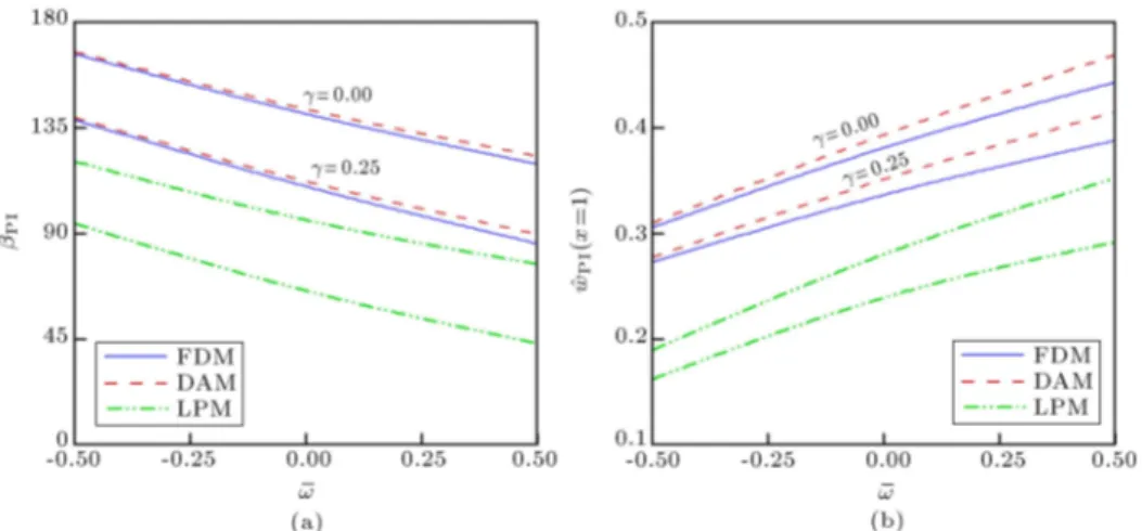
To show the impact of centrifugal force on the behavior of the double-sided actuator, the variations of PI and pull-in deection ( ^wPI(x = 1)) as a function
of ! are illustrated in Figure 3 for various values of Casimir parameter . In this gure, both positive and negative values of the centrifugal force are considered. As seen, a negative centrifugal force increases pull-in voltage (PI), while a positive centrifugal force
decreases the instability voltage of the sensor. In other words, for positive values of the centrifugal force, an increase in the angular speed leads to a decrease of the pull-in voltage. On the other hand, increasing the angular velocity increases the stability threshold of the systems for negative values of the centrifugal force. 4.2. Paddle-type actuator
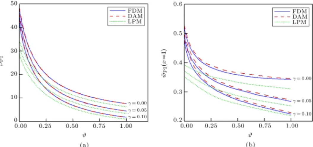
To demonstrate the eect of the paddle geometry on the stability, the variation of the instability charac-teristics versus geometrical parameter # is plotted in Figure 4. Parameter # represents the ratio between the rigid plate surface area over the nanowire surface area. As shown, with increasing #, instability voltage (PI)
and deection ( ^wPI(x = 1)) decrease. This implies that
an increase in the plate surface increases the external forces and reduces the stability threshold. Moreover,
Figure 2. The variation of the instability characteristics versus (k = 25, ! = 0, = 1 and = 0 for = 0 and = 0:4): (a) The pull-in voltage and (b) the pull-in deection.
Figure 3. The variation of the pull-in characteristics versus ! for dierent values of (k = 10, = 1:0, = 0 and = 1:25): (a) The pull-in voltage and (b) the pull-in deection.
Figure 4. The variation of the pull-in characteristics versus # for dierent values of (k = 5, = 0:5, = 0:1, ! = 0, = 0:5 and = 0): (a) The pull-in voltage and (b) the pull-in deection.
Figure 5. The variations of (a) PI and (b) ^wPI(x = 1) versus ! for dierent values of (k = 10, = 0:5, = 0:1,
= 0:5, = 0, and # = 0:1).
Figure 4(a) and (b) show that the inuence of the Casimir force on the stability is more pronounced for higher # values.
Figure 5 shows the pull-in characteristics of the sensor as a function of the centrifugal force. This gure depicts that for positive values of the centrifugal force, the pull-in voltage decreases as the angular speed increases. Furthermore, for negative values of the centrifugal force, an increase in the angular velocity increases the instability threshold of the sys-tems.
Finally, note that the DAM is an approximation method. For example, in Figure 2, the dierence between the pull-in voltages obtained by 8th order DAM polynomial and the FDM is less than 4%, which is acceptable for most of engineering designs. The results of the DAM can be more close to those of numerical solution by increasing the number of selected series terms [53]. On the other hand, the LPM is a very simple model for modeling the pull-in behavior of NEMS, while LPM results are not very close to the
numerical solution, and they have the advantage of providing a closed-form relation which can interpret the physical phenomena without mathematical complexity. This is very useful for engineers and designers. 5. Conclusions
The couple stress theory was employed for modeling the eect of the centrifugal force on the electromechanical instability of paddle-type and double-sided sensors in-corporating the size-dependency and the Casimir force. It was found that for positive values of the centrifugal force, pull-in voltage decreases as the angular speed increases. On the other hand, for negative values of the centrifugal force, increase in the angular velocity increases the stability threshold of the systems. The Casimir attraction decreases the pull-in characteristics of the actuators. The good agreement was observed between DAM and FDM, while LPM provided less precise results; however, this model simply explains the instability behavior without mathematical complexity.
References
1. Sedighi, H.M. and Shirazi, K.H. \Dynamic pull-in pull-instability of double-sided actuated nano-torsional switches", Acta Mech. Solida Sin., 28(1), pp. 91-101 (2014).
2. Fu, Y., Zhang, J. and Wan, L. \Application of the energy balance method to a nonlinear oscillator arising in the microelectromechanical system (MEMS)", Curr. Appl. Phys., 11(3), pp. 482-485 (2011).
3. Ke, C. \Resonant pull-in of a double-sided driven nanotube-based electromechanical resonator", J. of Appl. Phys., 105(2), p. 024301 (2009).
4. Bao, M., Analysis and Design Principles of MEMS Devices, Elsevier (2005).
5. Khan, Y. and Akbarzade, M. \Dynamic analysis of nonlinear oscillator equation arising in double-sided driven clamped microbeam-based electromechanical resonator", Z. Naturforsch., 67(8), p. 435 (2012).
6. Sedighi, H.M., Shirazi, K.H. and Changizian, M. \The eect of amplitude of vibration on the pull-in pull-instability of double-sided actuated micro-switch resonators", J. of Appl. Mech. and Tech. Phys., 56(2), 304-313 (2015).
7. Dashtaki, P.M. and Tadi Beni, Y. \Eects of Casimir force and thermal stresses on the buckling of elec-trostatic nanobridges based on couple stress theory", Arab. J. for Sci. and Eng., 39(7), pp. 5753-5763 (2014).
8. Ouakad, H.M. \The response of a micro-electro-mechanical system (MEMS) cantilever-paddle gas sen-sor to mechanical shock loads", J. of Vib. and Control, 21(14), pp. 2739-2754 (2013).
9. Yan, D., Khajepour, A. and Mansour, R. \Design and modeling of a MEMS bidirectional vertical thermal actuator", J. of Micromech. and Microeng., 14(7), p. 841 (2004).
10. Zhang, X.C., Myers, E.B., Sader, J.E. and Roukes, M.L. \Nanomechanical torsional resonators for frequency-shift infrared thermal sensing", Nano Lett., 13(4), pp. 1528-1534 (2013).
11. Tong, C.J., Cheng, Y.C., Lin, M.T., Chung, K.J., Hsu, J.S. and Wu, C.L. \Optical micro-paddle beam deection measurement for electrostatic mechanical testing of nano-scale thin lm application to MEMS", Microsys. Technol., 16(7), pp. 1131-1137 (2010).
12. Qian, Y., Lou, L., Tsai, M.J. and Lee, C. \A dual-silicon-nanowires based U-shape nanoelectromechani-cal switch with low pull-in voltage", Appl. Phys. Lett., 100(11), p. 113102 (2012).
13. Ahmad, F., Dennis, J.O., Hamid, N.H., Khir, M.H.M. and Ahmed, A.Y. \Design and modeling of MEMS resonator for magnetic eld sensing using hybrid actua-tion technique", In Circuits and Systems (APCCAS), 2010 IEEE Asia Pacic Conference on, pp. 827-830 (Dec. 2010).
14. Koukharenko, E., Beeby, S.P., Tudor, M.J., White, N.M., O'Donnell, T., Saha, C., Kulkarni, S. and Roy, S. \Microelectromechanical systems vibration powered electromagnetic generator for wireless sensor applications", Microsys. Technol., 12(10-11), pp. 1071-1077 (2006).
15. Beeby, S.P., Tudor, M.J., Koukharenko, E., White, N.M., O'Donnell, T., Saha, Kulkarni, S. and Roy, S. \Design, fabrication and simulations of microelectro-magnetic vibration powered generator for low power MEMS" At Symposium on Design, Test, Integration and Packaging of MEMS/MOEMS, Switzerland, pp. 374-379 (2005).
16. Firdaus, S.M., Omar, H. and Azid, I.A., High Sen-sitive Piezoresistive Cantilever MEMS Based Sensor by Introducing Stress Concentration Region (SCR), INTECH Open Access Publisher (2012).
17. Nayfeh, A.H., Ouakad, H.M., Najar, F., Choura, S. and Abdel-Rahman, E.M. \Nonlinear dynamics of a resonant gas sensor", Nonlinear Dynam., 59(4), pp. 607-618 (2010).
18. Bodson, M., Chiasson, J. and Novotnak, R.T. \Non-linear speed observer for high-performance induction motor control", Ind. Electron., IEEE T., 42(4), pp. 337-343 (1995).
19. Renaudin, L., Bonnardot, F., Musy, O., Doray, J.B. and Remond, D. \Natural roller bearing fault detection by angular measurement of true instantaneous angular speed", Mech. Syst. and Signal Pr., 24(7), pp. 1998-2011 (2010).
20. Lebold, M.S., Maynard, K., Reichard, K., Trethewey, M., Bieryla, D., Lissenden, C. and Dobbins, D. \Using torsional vibration analysis as a synergistic method for crack detection in rotating equipment", In Aerospace Conference, Proceedings, 6, pp. 3517-3527, IEEE (March 2004).
21. Jywe, W.Y. and Chen, C.J. \The development of a high-speed spindle measurement system using a laser diode and a quadrants sensor", Int. J. of Mach. Tool. and Manu., 45(10), pp. 1162-1170 (2005).
22. Huang, C.T., Li, P.N., Pai, C.Y., Leu, T.S. and Jen, C.P. \Design and simulation of a microu-idic blood-plasma separation chip using microchannel structures", Separ. Sci. and Technol., 45(1), pp. 42-49 (2009).
23. Hou, C., Wu, Y., Zeng, X., Zhao, S., Zhou, Q. and Yang, G. \Novel high sensitivity accelerometer based on a microber loop resonator", Opt. Eng., 49(1), pp. 014402-014402 (2010).
24. Azimloo, H., Rezazadeh, G., Shabani, R. and Sheikhlou, M. \Bifurcation analysis of an electro-statically actuated micro-beam in the presence of centrifugal forces", Int. J. of Non-Lin. Mech., 67, pp. 7-15 (2014).
25. Shah-Mohammadi-Azar, A., Azimloo, H., Rezazadeh, G., Shabani, R. and Tousi, B. \On the modeling of a capacitive angular speed measurement sensor", Measurement, 46(10), pp. 3976-3981 (2013).
26. Lin, W.H. and Zhao, Y.P. \Nonlinear behavior for nanoscale electrostatic actuators with Casimir force", Chaos, Soliton. & Frac., 23(5), pp. 1777-1785 (2005).
27. Lin, W.H. and Zhao, Y.P. \Casimir eect on the pull-in parameters of nanometer switches", Microsys. Technol., 11(2-3), pp. 80-85 (2005).
28. Tadi Beni, Y., Koochi, A. and Abadyan, M. \The-oretical study of the eect of Casimir force, elastic boundary conditions and size dependency on the pull-in pull-instability of beam-type NEMS", Physica E, 43(4), pp. 979-988 (2011).
29. Mokhtari, J., Farrokhabadi, A., Rach, R. and Abadyan, M. \Theoretical modeling of the eect of Casimir attraction on the electrostatic instability of nanowire-fabricated actuators", Physica E, 68, pp. 149-158 (2015).
30. Farrokhabadi, A., Mokhtari, J., Rach, R. and Abadyan, M. \Modeling the inuence of the Casimir force on the pull-in instability of nanowire-fabricated nanotweezers", Int. J. of Mod.Phys. B, 29(02), p. 1450245 (2014).
31. Bordag, M., Mohideen, U. and Mostepanenko, V.M. \New developments in the Casimir eect", Phys. Rep., 353(1), pp. 1-205 (2001).
32. Emig, T., Jae, R.L., Kardar, M. and Scardicchio, A. \Casimir interaction between a plate and a cylinder", Phys. Rev. Lett., 96(8), p. 080403 (2006).
33. Lam, D.C.C., Yang, F., Chong, A.C.M., Wang, J. and Tong, P. \Experiments and theory in strain gradient elasticity", J. of the Mech. and Phys. of Solids, 51(8), pp. 1477-1508 (2003).
34. McFarland, A.W. and Colton, J.S. \Role of mate-rial microstructure in plate stiness with relevance to microcantilever sensors", J. of Micromech. and Microeng., 15(5), p. 1060 (2005).
35. Eringen, A.C. and Edelen, D.G.B. \On nonlocal elas-ticity", Int. J. of Eng. Sci., 10(3), pp. 233-248 (1972).
36. Ejike, U.B.C.O. \The plane circular crack problem in the linearized couple-stress theory", Int. J. Eng. Sci., 7, pp. 947-961 (1969).
37. Sedighi, H.M., Changizian, M. and Noghrehabadi, A. \Dynamic pull-in instability of geometrically nonlinear actuated micro-beams based on the modied couple stress theory", Lat. Am. J. of Solids and Stru., 11(5), pp. 810-825 (2014).
38. Sedighi, H.M. \Modeling of surface stress eects on the dynamic behavior of actuated non-classical nano-bridges", T. of the Can. Soc. for Mech. Eng., 39(2), pp. 137-151 (2015).
39. Lam, D.C.C., Yang, F., Chong, A.C.M., Wang, J. and Tong, P. \Experiments and theory in strain gradient elasticity", J. of the Mech. and Phys. of Solids, 51, pp. 1477-1503 (2003).
40. Yang, F.A.C.M., Chong, A.C.M., Lam, D.C.C. and Tong, P. \Couple stress based strain gradient theory for elasticity", Int. J. of Solids and Stru., 39(10), pp. 2731-2743 (2002).
41. Anthoine, A. \Eect of couple-stresses on the elastic bending of beams", Int. J. of Solids and Stru., 37, pp. 1003-1018 (2000).
42. Fathalilou, M., Sadeghi, M. and Rezazadeh, G. \Micro-inertia eects on the dynamic characteristics of micro-beams considering the couple stress theory", Mech. Res. Commun., 60, pp. 74-80 (2014).
43. Fathalilou, M., Sadeghi, M. and Rezazadeh, G. \Gap dependent bifurcation behavior of a nano-beam sub-jected to a nonlinear electrostatic pressure", Lat. Am. J. of Solids and Stru., 11, pp. 2426-2443 (2014).
44. Mindlin, R.D. \Inuence of couple-stresses on stress-concentrations", Exp. Mech., 3, pp. 1-7 (1963).
45. Georgiadis, H.G. and Velgaki, E.G. \High-frequency Rayleigh waves in materials with micro-structure and couple-stress eects", Int. J. of Solids and Stru., 40, pp. 2501-2520 (2003).
46. Koochi, A., Kazemi, A.S., Tadi Beni, Y., Yekrangi, A. and Abadyan, M. \Theoretical study of the eect of Casimir attraction on the pull-in behavior of beam-type NEMS using modied Adomian method", Physica E, 43, pp. 625-632 (2011).
47. Jackson, J.D., Classical Electrodynamics, Wiley, New York (1998).
48. Hayt, W.H., Engineering Electromagnetics, New York: McGraw-Hill (1981).
49. Duan, J.S. \Convenient analytic recurrence algorithms for the Adomian polynomials", Appl. Math. and Com-put., 217(13), pp. 6337-6348 (2011).
50. Adomian, G., Nonlinear Stochastic Operator Equa-tions, Academic Press, Orlando, FL (1986).
51. Duan, J.S. \An ecient algorithm for the multivariable Adomian polynomials", Appl. Math. and Comput., 217(6), pp. 2456-2467 (2010).
52. Abdi, J., Koochi, A., Kazemi, A.S. and Abadyan, M. \Modeling the eects of size dependence and disper-sion forces on the pull-in instability of electrostatic cantilever NEMS using modied couple stress theory", Smar. Mater. and Struct., 20(5), p. 055011 (2011).
53. Koochi, A. and Abadyan, M. \Eciency of modied Adomian decomposition for simulating the instability of nano-electromechanical switches: comparison with the conventional decomposition method". Tr. in Appl. Sci. Res., 7(1), pp. 57-67 (2012).
54. Ramezani, A., Alasty, A. and Akbari, J. \Analytical investigation and numerical verication of Casimir eect on electrostatic nano-cantilevers", Microsys. Technol., 14, pp. 145-157 (2008).
55. Ke, C. and Espinosa, H.D. \Numerical analysis of nanotube-based NEMS devices-Part I: Electrostatic charge distribution on multiwalled nanotubes", J. of Appl. Mech., 72(5), pp. 726-731 (2005).
Appendix A
Large deformation theory
When double-sided actuator exhibits large displace-ments, the curvature of the deection should be con-sidered; therefore, governing changes into [54]:
(EeI +Al2) d 2
dX2
2 4 d2w
dX2 1+
dw dX
2! 323
5=fext:
(A.1) After some manipulations and using Eq. (25), the nondimensional governing equation is obtained as:
(1 + )ddx4w^4 =
"
p
(1 ^w) [1+k (1 ^w)] arccos h2(1+2k (1 ^w))
+
(1 w)^ 72
p
(+ ^w) [1+k (+ ^w)] arccos h2(1+2k (+ ^w))
( + ^w)72 + !
# h
1 + ( ^w0)2i2
+ 323 ^w0w^00w^000+ ^w003
1 + ( ^w0)2
154w^02w^003
h
1 + ( ^w0)2i2; (A.2)
where:
= DL; (A.3)
and the prime denotes dierentiation with respect to x. When approaches zero, Eq. (A.2) turns into Eq. (24a).
The numerical simulation results shown in Ta-ble A.1 reveal that the eect of the large deformation on the pull-in parameters is negligible for < 0:1. Table A.1 demonstrates that Eq. (24) has enough ac-curacy for description of the elastic behavior of double-sided actuator from small to large displacements when
the initial gap to the length ratio is less than 0.1 (i.e., < 0:1), which is the case in most double-sided actuators designs.
Appendix B
Tip-charge concentration
The impact of tip-charge concentration on the defor-mation of cantilever might be considerable [55]. Thus, the tip-charge concentration force can be written as follows:
felec;c= 0:85[R(D + R)2]13felec(L); (B.1)
where (x) is the Dirac delta function.
For the double-sided actuator, by using Eqs. (18), (20), (22), and (B.1), the nondimensional governing equation can be explained by considering the tip-charge concentration as shown in Box B.1.
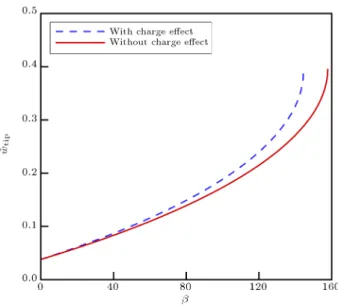
To examine the impact of tip-charge concentra-tion on the behavior of the double-sided actuator, vari-ation of the tip deection ( ^wtip) versus nondimensional
voltage () is presented in Figure B.1. As shown above,
Figure B.1. 1 The variation of ^wtipversus : Impact of
tip-charge concentration ( = 0:1, = 0:3, k = 20, = 2:0, ! = 0, = 1:0, and = 0).
Table A.1. Pull-in parameters of dierent values of k using small ( = 0) and large deformation ( = 0:1) theories when = 0:4, = 2, = 1, and = 0.
k 200 150 100 75 50 25 10
Small deformation ( = 0)
PI 587.57 463.83 330.08 257.94 180.76 96.16 39.79
^
wPI 0.35263 0.35118 0.34934 0.34820 0.346057 0.34283 0.33743
Large deformation ( = 0:1)
PI 585.97 462.58 329.20 257.25 180.29 95.91 39.69
^