Received 24 April 2016; received in revised form 12 June 2016; accepted 30 July 2016.
To cite this article: Farooq and Harmain. (2016). Performance characteristic in hydrodynamic water cooled thrust bearings. Jurnal Tribologi 10, pp.28-47.
Performance characteristics in hydrodynamic water cooled thrust bearings
Farooq Ahmad Najar*, G.A. Harmain
Mechanical Engineering Department, National Institute of Technology Srinagar, 190006 India.
*Corresponding author: [email protected]
HIGHLIGHTS
Novel cooling arrangement has been used to study the influence on heat transfer in thrust bearing. Performance characteristics of thrust bearing increases with the introduction of novel method of
cooling within the thrust element.
Temperature of the oil film is controlled to a great extent with the varying flow velocity of water ranging from 0.5 m/s to 2.0 m/s, flowing in the cooling duct.
ABSTRACT
This paper deals with the study of the influence on performance characteristics of a thrust bearing with the introduction of cooling circuit and flow velocity of coolant within the designed thrust bearings is described. New method of cooling circuit configuration is taken into consideration and water has been chosen as a coolant here in the present work. Flow velocity of coolant, ranging from 0.5m/s to 2.0m/s is proposed. The Finite difference based numerical model has been developed in order to notice the effect on the heat transfer on a large hydrodynamic lubrication thrust bearing in-terms of its performance characteristics. In the present work, the solution of Reynolds equation, an energy equation with viscosity variation and Fourier heat conduction equations, applied with appropriate boundary conditions. From the present investigation, it is observed significant amount of heat content is removed from the bearing with the increase of flow velocity of coolant in an embedded cooling duct within the pad. An important parameter among performance characteristics has prevailed a significant increase in hydrodynamic pressure generation which in turn subsequently increases the load carrying capacity which has been never ever documented in the background literature.
Keywords:
| Finite difference method | Flow velocity | Heat transfer enhancement | Hydrodynamic thrust bearings |
1.0 INTRODUCTION
the value of heat exchange significantly varies as a function of different variables. The properties of the fluid flowing around the pad surface and the inlet velocity and the nature of the fluid flow, and the geometry of the surfaces. These are the elementary factors and it is observed in the results of published bearing related experimental studies as reported by (Gregory, 1977) in which the author has carried out a research and generated the data based on 267mm self-equalizing thrust pad bearing with the high speed of shaft (up to 14,000 rpm). Another set of experimental investigation regarding heat transfer in thrust bearings reported by (Neal, 1982) and demonstrated experimentally thrust bearings with different number of pads set configurations outer diameters of 150 mm, results prevailed that 12% of heat losses generated in the oil film were transferred through the pad free surfaces to the surrounding environment. However, the investigation presented by (Neal, 1982), there is a dependence of heat transfer in pads, on the number of bearing pads and the clearance between them.
A research on thermal effects in thrust bearings includes computational studies (commonly based on the numerical solution of the Reynolds equation and the energy equation and recently on CFD) and experimental based as well. Numerical studies based on the Reynolds equation and energy equation have demonstrated the performance potential of temperature related analysis, in thrust bearings (Buscaglia et al., 2005; Ozalp and Umur, 2006; Marian et al., 2007). Since thermal effects may substantially effect on bearing performance characteristics: excess heat energy dissipation increases the lubricant temperature which in turn decreases the local viscosity value of the lubricating oil and hence reducing the performance in terms of load carrying capacity (LCC). Studies have considered these effects as (THD) including (Dadauche et al., 2000; Dadauche et al., 2006). A CFD analysis of 3D textured based rectangular sliders has been recently reported in (Cupillard et al., 2009). CFD studies offer substantial advantages, in particular the ability to modify design as per the requirement of parameters in a way and quantify the effects on performance characteristics. However, many of the texture designs introduced to the surface of the pads, in order to understand the role of these texture patterns, following relevant recent studies (Marian et al., 2007; Pascovici et al., 2009).
In the present work, an effort has been made to remove heat due to viscous dissipation of lubricant during operation of the thrust bearings. Thermal effects on a large hydrodynamic lubrication thrust bearing component(s) are taken into account. The treatment of the fluid–solid interaction and energy transport equation, this insures the temperature and heat flux at the interface between solid and the fluid part inside the pad geometry. Different set of flow velocities of water is tested during investigation to determine the effect of heat transfer from the integral heat source (pad) to the flowing fluid (cooling pipe) as sink, thus carrying away heat to a great extent, which helps the system to withstand for higher loads and prolong operation.
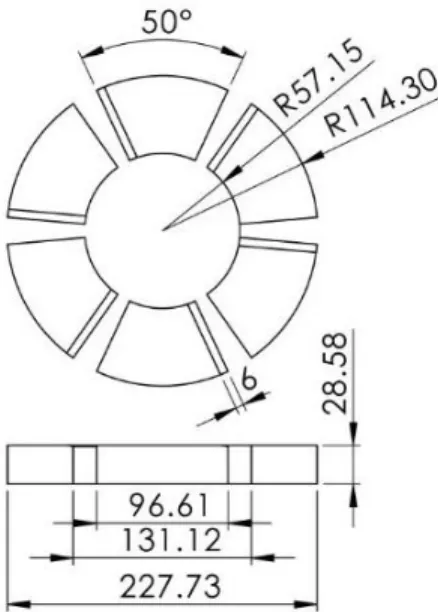
Figure 1: Sketch for conventional thrust bearing with characteristic dimensions
(a) (b)
Figure 2: (a) 3D solid model and (b) sketch for thrust bearing with novel design with characteristic dimensions
2.0
GOVERNING EQUATIONS
2.1 Reynolds’s Equation
do not change due to change in curvature of runner because the curvature of the runner is much larger when compared with the oil film thickness.
The analysis of hydrodynamic thrust bearings has been based on the Reynolds’ equation presented in Eq.1 for the pressure profile. With the increase in capacity of computing, numerical models including the influences of viscosity variations along and across the lubricating film have been developed.
The temperature of the runner along its runner surface varies much less than the temperatures in the thrust pad active face. The temperature of the runner varies by less than 11o C and the temperature along thrust pad rises by 15–20oC as referred in (Ettles and Anderson, 1991). Values of viscosity obtained from the temperature field in the oil film are substituted in the Reynolds’ equation, to determine the pressure field. In load estimation the pressure ‘fitting’ at the edges is made more appropriate to suit realistic condition shown in (Chaturvedi et al., 1989).
∂ ∂r(
rh3 η
∂P ∂r) +
∂ ∂θ(
h3 ηr
∂P
∂θ) = 6ωr ∂P
∂θ (1)
Where h is the film thickness, μ is the viscosity of oil and ω is the angular speed of the runner.
2.2 Equation of Oil Film
The equation of the oil film used in this work is given in Eq.2
h = h0 + hs[1 − θ
θt] (2)
Where h is the film thickness, h0 is the minimum film thickness, hs is the amount of taper, θ and θt are the general angular extent and total angular extent of the pad respectively. The geometry of the oil film is shown in Figure 3.
2.3 Load Carrying Capacity
Load carrying capacity is one of the important characteristics in hydrodynamic lubrication, it is simply the integral form of pressure distribution presented in Eq.3.
𝑊 = ∫ ∫ (𝑃𝑅)𝑑𝜃𝑑𝑅𝑅𝑅0 𝐼
𝜃=𝜃𝑡
𝜃=0 (3)
2.4 Energy Equation
Due to viscous dissipation in the oil film, the heat is generated and its transport is totally governed by the energy equation. It is assumed that conduction of heat within the film thickness is neglected and therefore, it is necessary that heat is inevitable to get conducted towards the tribo surfaces, so the energy equation for a laminar flow and incompressible lubricating oil is represented as in Eq.4.
ρCp[qr ∂T ∂r+ qθ
1 r
∂T
∂r] = Ė – Ë − E⃛ (4)
qr = h3 12η
∂p ∂r
qθ = rωh 2 − h3 12η 1 r ∂p ∂θ
Ė =η h(ωr
2) + h3 12η{( 1 r ∂p ∂θ) 2 + (∂p
∂r) 2
}
Where ρ the density of oil is, 𝐶𝑝 is the specific heat of the oil and 𝜂 is the viscosity of lubricant.
2.5 Heat Conduction Equation
Generally, heat generated in the thin film is reduced by convection in the oil film as the film is in between the sliding surfaces and a major part of the heat is removed by conduction to the surfaces. The conduction of heat in the thrust pad is governed by the Fourier conduction equation, which is presented in Eq.5 in terms of polar coordinates:
(∂2T ∂r2) +
1 r(
∂T ∂r) +
1 r2(
∂2T ∂θ2) + (
∂2T ∂θ2) +
qt
K = 0 (5)
2.6 Boundary Conditions
With the initial conditions of pressure, where P is the pressure, T the temperature, r and are the cylindrical coordinates in radial and circumferential directions respectively. The temperature on the top surface of the Pad (active face) is equal to the temperature in the oil film (Eq.6).
𝜕𝑃 𝜕𝜃= 0 ; 𝜕𝑇 𝜕𝑟 = 0 ; 𝜕𝑃 𝜕𝑟= 0;
𝑇𝑜𝑖𝑙 = 𝑇𝑝𝑎𝑑 (6)
2.7 Heat transfer to the embedded circuit
In the present analysis it is assumed that the axis of the pipe line matches with the grid network. The pipeline is divided into several segments. The inlet temperature for the first segment is known. The outlet bulk temperature is obtained by considering the heat flow from the wall to the fluid is equivalent with the heat carried away by the fluid, as in Eq.7.
htπdl (Tw− (Tb1 +Tb2
2 )) = m ̇Cp (Tb2 −Tb1) (7)
ṁ = (ρπd 2U
m
4 )
Where 𝑚̇ is the mass flow rate, ℎ𝑡 is the heat transfer coefficient, d is the pipe diameter, l is the length of each segment, 𝑇𝑤is the wall temperature, 𝑇𝑏1and 𝑇𝑏2are the inlet and outlet bulk temperatures respectively. 𝑈𝑚 is the flow velocity of water. The value of ℎ𝑡 is obtained from Nusselt’s number for pipe flow (Eq.8).
Nu = (ht d
Kw) (8)
Where 𝐾𝑤is the thermal conductivity of water. The outlet bulk temperature is given as Eq.9.
Tb2 =
2πhdlTw − Tb1(πhdl−2mCṗ )
2m ̇Cp+πhdl (9)
In the present investigation data set of thrust bearing has been chosen in this form. A Thrust bearing with Sector shaped six pads, inner radius of 57.15(mm) and outer radius of 114.3 mm, pad thickness is 28.58 mm, oil type SAE30, exit film thickness h0 = 23μm, Pad angle 50°, Runner Speed is 900 rpm, viscosity of lubricant at inlet 0.07 Pa.s, bath tub temperature is 40°C, temperature of water at inlet is 20°C, diameter of embedded pipe is 2.0mm, density of lubricant is 855.0 kg/m3, Thermal conductivity of lubricating oil is 0.13 W/m/K, flow velocity of cooling water ranging from 0.5m/s to 2.0m/s.
2.8 Solution Procedure
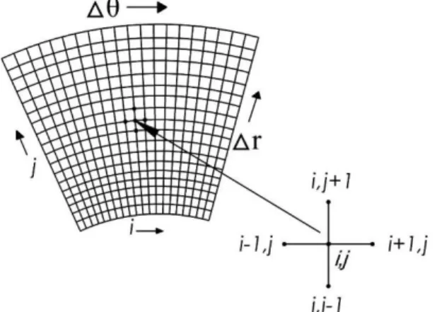
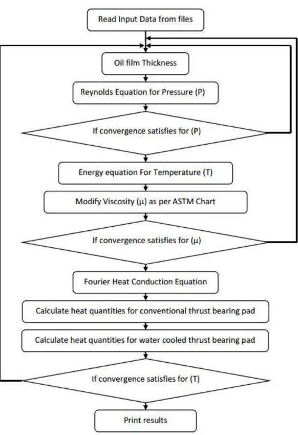
Finite difference scheme has been used to solve the partial differential and well known Gauss-seidel iterative method has been used for iteration purpose, as shown in Figure 4. Initial values of pressure are assumed zero for all the nodal points. Initial values of viscosity are taken corresponding to the inlet values of temperature (bath tub temperature) at all the nodal points. The film thickness values are obtained from standard expression. Initial values of temperature are assumed to be bath temperature at all the nodal points.
Figure 4: Finite difference scheme on sector shaped pad
marching through the thickness of the pad. Heat transfer quantities through various nodes are also evaluated in the process. Temperature values are evaluated at all nodal points with respect to the depth of the pad. This gives complete solution of a conventional type of thrust pad for temperature, pressure and viscosity profiles at the top of the pad. This also provides temperature values at all the nodal points with respect to depth and all the values for various modes of heat transfer. Water pipe arrangement is introduced, and cell by cell heat carried away by pipe network is evaluated and marching is performed using if and then logic along the path of the pipe. Input value of the flow velocity of water is chosen as given and the cases of laminar and turbulent flows have been evaluated separately using appropriate heat transfer relations. Heat transfer coefficient for the flow through the pipe has been obtained for all cases using a subroutine which simultaneously interpolates property values of water using interpolation based on lagrangian formulation. The convergence criteria for outlet bulk temperature of each cell of the pipe arrangement are chosen as in Eq.10. An appropriate value has been chosen for convergence. A grid study has been carried out starting from 21×21, 31×31, 41×41 and 91×91. Figure 4 gives the clear picture of the finite difference of 21×21 grid size which was earlier and then the grid size were results has been carried out is at 31×31. The flow chart for the numerical computation is shown in Figure 5.
𝜀 = 𝑇𝑏2𝑁−𝑇𝑏2
𝑇𝑏2𝑁 (10)
2.9 Validation of numerical model
3.0 RESULTS AND DISCUSSION
The pressure, temperature and viscosity distributions have been obtained on the data set in the example and compared with the results of (Gregory, 1977; Neal, 1982). A grid independence study was conducted. There are several cases which are presented to obtain the role of water cooling arrangement. The four cases of velocities give results for flow through the embedded water pipe. The oil properties (SAE-30) have been used. The fidelity of the algorithm was established for cases without water cooling arrangement by thorough comparison with works of Ozalp and Umur, 2006; Marian et al., 2007. A comparison for constant (and variable) viscosity of oil was obtained by applying the convergence criteria on viscosity and pressure as is given in this paper. There is good agreement on the data set an example by Ozalp and Umur, 2006 and Marian et al., 2007. The temperature profiles have also been obtained with respect to the depth of the pad to permit the assessment of temperature with respect to the depth. This was possible by running the code for the bearing pad without water cooling arrangement. This has been compared with the work presented in references of Ozalp and Umur, 2006; Marian et al., 2007, and a good agreement has been observed. Subsequent investigation has been focused on the problem for the determination of temperature profiles with the depth of the bearing pad at various sections through the thickness of the bearing pad. The temperature profiles have been obtained for the entire pad for different set of velocity flow of water through the water pipe embedded within the pad.
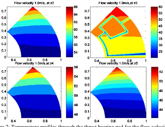
Figure 7: Temperature profiles through the thrust bearing pad for the flow velocity of 1.0m/s of water in the pipe embedded in the body of Sector shaped pad
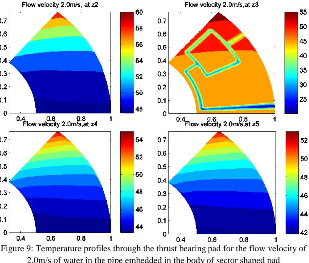
Figure 9: Temperature profiles through the thrust bearing pad for the flow velocity of 2.0m/s of water in the pipe embedded in the body of sector shaped pad
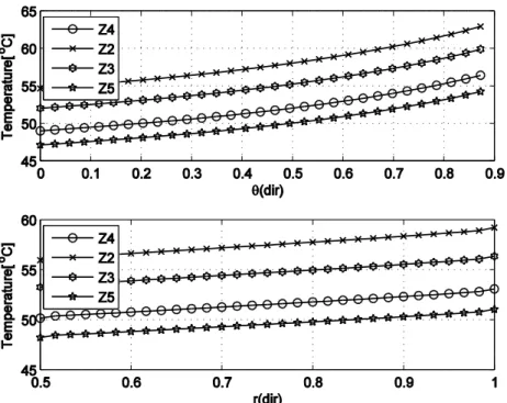
Figure 10: Centre line temperature distribution along the circumferential and radial direction, flow velocity of water at 0.5m/s in a pipe embedded in the body of Sector
shaped pad
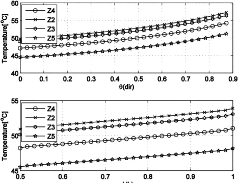
Figure 11: Centre line temperature distribution along the circumferential and radial direction, flow velocity of water at 1.0m/s in a pipe embedded in the body of the Sector
Figure 12: Centre line temperature distribution along the circumferential and radial direction, flow velocity of water at 1.5m/s in a pipe embedded in the body of Sector
shaped pad
Figure 13: Centre line temperature distribution along the circumferential and radial direction, flow velocity of water at 2.0m/s in a pipe embedded in the body of Sector
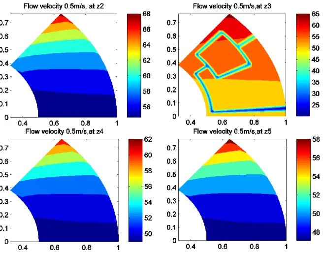
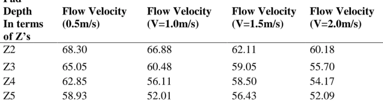
Table 1: Maximum nodal temperature (°C) at various depths of the pad Pad Depth In terms of Z’s Flow Velocity (0.5m/s) Flow Velocity (V=1.0m/s) Flow Velocity (V=1.5m/s) Flow Velocity (V=2.0m/s)
Z2 68.30 66.88 62.11 60.18
Z3 65.05 60.48 59.05 55.70
Z4 62.85 56.11 58.50 54.17
Z5 58.93 52.01 56.43 52.09
Figure 14 gives a clear interpretation of pressure generation in the oil film when the cooling is at 0.5m/s and it is evident that with the increase in flow velocity maximum amount of heat is taken away and hence oil film generates more pressure, while the temperature profiles near the embedded pipe are dramatically disturbed in all the cases, the flow velocity of water causes more depression near the pipe while for all flow velocities of water the temperature is 40°C. The amount of heat taken by water circuit is shown for all the four cases for flow velocities of 0.5, 1.0, 1.5 and 2.0 m/s. It is observed that for a low velocity changing from 0.5m/s to 2.0m/s, the magnitude of heat taken away by water circuit is also increasing with the increase in flow velocities.
CONCLUSION
In this study, an analysis of water cooled thrust bearing was conducted. First of all, using FDM scheme Reynolds equation was solved parameters like film thickness and pressure distribution are fed to the energy equation in order to get the temperature distribution with and without viscosity variables taken into consideration. The main treatment is based on heat generation which is the source term of the generalized Fourier heat conduction equation. A numerical code was generated accordingly and the fidelity of algorithm has been achieved.
Eventually, from the present work, it concludes with the following points:
a) At 0.5 m/s flow velocity, the nodal temperature varies from 68.30°C to 60.18°C.
b) At 1.0 m/s flow velocity, the nodal temperature varies from 66.88°C to 52.01°C.
c) At 1.5 m/s flow velocity, the nodal temperature varies from 62.11°C to 56.43°C.
The main conclusion is as we go on increasing the level of flow velocity in the duct, heat transfer enhancement has prevailed to a great extent, in this way, the present work will serve as a breakthrough information for the designer to design thrust bearings which can withstand for higher loads and run prolong.
(a)
(b)
Figure 14: (a) 3D mesh plot of Pressure distribution in the lubricating oil film when the flow velocity of water at 1.5m/s in a pipe embedded in the body of Sector shaped pad, (b)
REFERENCES
Buscaglia, G.C., Ciuperca, I. and Jai, M., 2005. The effect of periodic textures on the static characteristics of thrust bearings. Journal of Tribology, 127(4), 899-902.
Chambers, W.S. and Mikula, A.M., 1988. Operational data for a large vertical thrust bearing in a pumped storage application. STLE Transactions, 31(1), 61-65.
Chaturvedi, K.K., Athre, K., Nath, Y. and Biswas, S., 1989. Refinement in estimation of load capacity and temperature distribution of pad bearing. Proceedings of the of Eurotrib-89, 5th international conference on Tribology 1989. Helisinki, Finland. Cupillard, S., Glavatskih, S. and Cervantes, M.J., 2009. 3D thermohydrodynamic analysis
of a textured slider. Tribology International, 42(10), 1487-1495.
Ettles, C.M. and Anderson, H.G., 1991. Three-Dimensional thermoelastic solutions of thrust bearings using code Marmac. Journal of Tribology, 113(2), 405-412.
Ettles, C.M., 1980. Size effects in tilting pad thrust bearings. Wear, 59(1), 231-245. Ettles, C.M., 1991. Some factors affecting the design of spring supported thrust bearings
in hydroelectric generators. Journal of Tribology, 113(3), 626-632.
Ettles, C.M.M. and Cameron, A., 1968. Considerations of flow across a bearing groove. Journal of Lubrication Technology, 90(1), 312-319.
Gregory, R.S., 1977. Operating characteristics of a fluid–film thrust bearing subjected to high shaft speeds. Super Laminar Flow in Bearings.
Kawaike, K., Okano, K. and Furukawa, Y., 1979. Performance of a large thrust bearing with minimized thermal distortion. ASLE Transactions, 22(2), 125-134.
Marian, V.G., Kilian, M. and Scholz, W., 2007. Theoretical and experimental analysis of a partially textured thrust bearing with square dimples. Proceedings of the Institution of Mechanical Engineers, Part J: Journal of Engineering Tribology, 221(7), 771-778. Nayyar, S., 1988. Effect of hot carry over in the determination of temperature in thrust
bearings. M. Tech. Dissertation, IIT Delhi, India.
Neal, P.B., 1982. Heat transfer in pad thrust bearings. Proceedings of the Institution of Mechanical Engineers, 196(1), 217-228.
Ozalp, A.A. and Umur, H., 2006. Optimum surface profile design and performance evaluation of inclined slider. Current Science, 90(11), 1480-1491.
Pascovici, M.D., Cicone, T., Fillon, M. and Dobrica, M.B., 2009. Analytical investigation of a partially textured parallel slider. Proceedings of the Institution of Mechanical Engineers, Part J: Journal of Engineering Tribology, 223(2), 151-158.
Ramakrishna, K.M., 1987. Lubricant viscosity variation in pad bearings. M. Tech. Dissertation, IIT Delhi, India.