http://www.sciencepublishinggroup.com/j/ajetm doi: 10.11648/j.ajetm.20170206.15
ISSN: 2575-1948 (Print); ISSN: 2575-1441 (Online)
Grid-Connected Control System for Three-Phase
Bidirectional DC/AC Converter to Exploit Photovoltaic
Power Generation
Le Tien Phong, Do Trung Hai
Electrical Faculty, Thai Nguyen University of Technology, Thai Nguyen, Viet Nam
Email address:
mrphonghtd1246@gmail.com (Le T. Phong)
To cite this article:
Le Tien Phong, Do Trung Hai. Grid-Connected Control System for Three-Phase Bidirectional DC/AC Converter to Exploit Photovoltaic Power Generation. American Journal of Engineering and Technology Management. Vol. 2, No. 6, 2017, pp. 98-107.
doi: 10.11648/j.ajetm.20170206.15
Received: November 17, 2017; Accepted: November 27, 2017; Published: December 20, 2017
Abstract:
A grid-connetected control system is proposed in this paper to regulate three-phase bidirectional DC/AC converters in distribution grid exploiting photovoltaic power generation and not having energy storage at the DC side. To interact power flow at two its sides, statbilize voltage at the DCbus and synchronize with the grid, it includes an inner current controller and an outer voltage controller in a cascaded structure. Using small signal modeling and information about voltage at the point of common coupling and DCbus, control parameters for controllers are determined to balance power between photovoltaic system side and grid side. Simulation results show that the grid-connected control system helps the three-phase bidirectional DC/AC converter meet all requirements very well due to the balance of power at its sides to hold voltage at DC side at a fixed value, grid synchronization and low harmonic distortion total for current and voltage waveforms. They also represents the capability to exploit maximum available power of photovoltaic power generation under any operational condition.Keywords:
Bidirectional DC/AC Converter, Grid-Connected Control, Photovoltaic Power Generation, Synchoronization, Small Signal Model1. Introduction
Basing on the development of semiconductor devices and advanced control technique, DC/DC and DC/AC power converters help photovoltaic power generation (PVg) become more popularly in distribution system. To exploit energy from PVg and generate it to the grid or the utility, above power converters are often used in a cascaded structure with an intermediate element that was held at a fixed voltage value, called DCbus. In addition, they also need to be controlled by strategies to execute individual purposes [11], [15].
For DC/DC converters, their input terminals are often controlled to track instantaneous maximum power point (MPP) of PVg under any operational condition. To execute this task, controllers in systems exploiting PVg often have common structure that is combined by a control technique and a technique to determine MPP to construct some methods. Depending on the complexity and the number of
devices, they can provide different values of energy efficiency or suffer from high cost. One of the best method that help to regulate PVg proposed recently is IB-AVC method, combining iterative and bisectional technique in maximum power point tracker (MPPT) and average voltage control (AVC). This method requires to use a pyranometer (PYR) to measure power of electromagnetic radiation (G) and a temperature sensor (TempS) to measure temperature (T) at p-n junctions. In the context of low cost for PYR and TempS, the IB-AVC method was considered as a potential approach to improve efficiency for whole system in the constrain of PV homogeneous cells [7].
cost. In systems not having energy storage, it need to use bidirectional DC/AC converters to interact power with the grid in two directions (from DC side to AC side and from AC side to DC side in reverse). Although these converters are difficult to control, they can help to decrease cost and increase longlife of whole system. Therefore, most systems exploiting PVg often use bidirectional converters to synchronize and interact power with the grid [12], [15].
To work as an intermediate element between DCbus and the grid in a PV system, input terminals of bidirectional DC/AC converters are also controlled to balance power at DC side and AC side to hold voltage at DCbus at a fixed value. An important unit in three-phase system to synchronize to the grid is a phase-locked loop (PLL). It helps to track the phase angle of the input signal quickly and accurately [3], [13]. Control of three-phase or single-phase bidirectional converters always have the same structure with two control loops. In systems not having energy storage at DCbus, inner current loop is used to regulate the current at the point of common coupling (PCC) corresponding to the interactive power and outer voltage loop to hold voltage at DCbus at a fixed value [8], [10].
Although the power flow from PVg to the grid is controlled by combination IB-AVC method to control a DC/DC boost converter and a grid-connected control system, this paper only proposes a method to regulate a three-phase bidirectional DC/AC converter in systems exploiting energy from PVg and not having energy storage linked to DCbus. For this purpose, the structure of whole system and mathematical model of some main blocks are represented in Section II. In Section III, the grid-connected control system is designed to determine control parameters of current and voltage controllers. In Section IV, simulation results and comments are represented. Finally, some conclusions are given about overall design.
2. Structural Systems and Mathematical
Model
2.1. Structure of Whole System
The whole system structure is described in Figure 1 [12], [15].
Figure 1. The structure of whole system.
DC/DC boost converter is used in this system to reduce quantity of connecting panel in series. To regulate this
converter, the IB-AVC method is designed to exploit maximum available power of PVg under any operational condition using information about G, T, vpv, current through
the inductor in the DC/DC converter provided by sensors. The control system for this converter includes two control loops (inner current loop and outer voltage loop) to drive voltage at input its terminals to desired voltage (voltage at MPP of PVg) [7]. In any range time that has enough energy for PVg to create electrons, this control method will help to regulate PVg to make a power flow go through its power circuit to DCbus.
The grid-connected control system collects information about instantaneous current (ig) and voltage (ug) at PCC,
instantaneous voltage vdc at DCbus. Combining information
about angle voltage at PCC provided by a PLL, it must play an important role to hold voltage at DCbus at fixed value, synchronize the bidirectional DC/AC converter to the grid and generate power from PVg into the grid. In this case, the bidirectional DC/AC converter is considered as a linking unit that interacts power with the grid by regulating energy flow through the its power circuit.
Transformer is used to step up voltage corresponding to the grid voltage and help to filt harmonic waves of output voltage and current of the bidirectional DC/AC converter.
2.2. Modeling the Bidirectional DC/AC Converter
Power circuit of the bidirectional DC/AC converter is described in Figure 2 [1], [9], [11], [14].
iga, igb, igc: output currents of the bidirectional DC/AC
converter through A, B and C phases (generally called ig),
SW1, SW2, SW3, SW4, SW5, SW6 are controlled switches
such as MOSFET, IGBT,…
D1, D2, D3, D4, D5, D6 are diodes (non-controlled switches).
R and L are equivalent quantities of resistor and inductor at output bidirectional DC/AC converter. They can be calculated mainly by resistors and inductors of the filter and the transformer as depicted in (1):
trans filter trans filter
R=R +R , L=L +L (1)
where:
Rtrans and Ltrans are resistance and inductance of
transformer,
Rfilter and Lfilter are resistance and inductance of filter.
Rtdc is equivalent resistance of load linked to DCbus at DC
side of the bidirectional DC/AC converter.
Cdc is capacitance of capacitor linked to DCbus at DC side
of the bidirectional DC/AC converter.
Applying the Kirchhoff’s first law at AC side, we have (2) [10]:
ga gb gc
i +i +i =0 (2)
Applying the Kirchhoff’s second law at AC side for each phase, we have (3) [2], [10], [14]:
g
g (a,b,c)
di
L Ri u
dt + = ∆ (3)
where: ∆u(a, b,c) =uinv (a , b,c )−ug (a , b ,c )
uinv(a, b, c) is voltage vector of A, B or C phase at output
bidirectional DC/AC converter,
ug(a, b, c) is voltage vector of A, B or C phase at PCC.
2.3. Structure of Grid-Connected Control System
Structure of grid-connected control system is demonstrated in Figue 3 [2], [4], [6], [15].
Figure 3. Structure of grid-connected control system.
uinv and ig vectors are determined in αβ and dq coordinates as represented Figure 4 [4], [5].
Figure 4. The stationary and rotating vector relationship representations.
where: ωe = dθ/dt is electric fundamental frequency (rad/s).
Applying Park’s transform of three-phase vectors to dq rotating coordinates for ig and ∆u variables, we have (4), (5),
(6), (7) [10]:
d ga e gb e gc e
2 2 2
i i cos( t) i cos t i cos t
3 3 3
π π
= ω + ω − + ω +
(4)
q ga e gb e gc e
2 2 2
i i sin( t ) i sin t i sin t
3 3 3
π π
= − ω + ω − + ω +
(5)
d 2 a e b e 2 b e 2
V u cos( t) u cos t u cos t
3 3 3
π π
∆ = ∆ ω +∆ ω − +∆ ω +
(6)
q a e b e b e
2 2 2
V u sin( t) u sin t u sin t
3 3 3
π π
∆ = − ∆ ω + ∆ ω − + ∆ ω +
(7)
From (3), we have:
− ∆ =
− ∆ =
− ∆ =
gc c gc
gb b gb
ga a ga
i L R u L 1 dt di
i L R u L 1 dt di
i L R u L 1 dt di
Time derivative (4), using (4), (5), (6), (7) and system of equation (8), we have (9) and (10):
d
e q d d
di R 1
i i V
dt = ω −L + ∆L (9)
q
e d q q
di R 1
i i V
dt = −ω −L + ∆L (10)
From (9) and (10), we have the decoupling model of the bidirectional DC/AC converter in dq rotating coordinates as represented in Figure 3.
Figure 5. Decoupling model of bidirectional DC/AC converter in dq coordinates.
where: TL=L/R is contant time of the circuit.
3. Design the Grid-Connected Control System
3.1. Configuration of the Grid-Connected Control System
Figure 6. Configuration of grid-conneted control system in dq coordinates.
The configuration of the grid-connected control system in dq rotating coordinates is presented in Figure 6 [2], [15].
This control system has two control loops: outer voltage control loop and inner current control loop. Voltage at DCbus is held at a fixed value Vdcref, value of uref is calculated by
controllers to determine on-off time range by control pulse generator before sending to SWs in the bidirectional DC/AC
converter.
3.2. Determine Parameters of the Current Controller
Equivalent current loop circuit of the bidirectional DC/AC converter is depicted in Figure 7.
Figure 7. Equivalent current loop of the bidirectional DC/AC converter.
where: Gci (s) is transfer function of current controller,
GPWM (s) is transfer function of control pulse generator, approximately PWM S
1 G
T 1 s
2
=
pulse generator) [4],
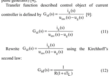
Transfer function described control object of current
controller is defined by id g
inv g
i (s) G (s)
u (s) u (s)
=
− [9]:
g id
inv g
i (s) G (s)
u (s) u (s)
=
− (11)
Rewrite id g
inv g
i (s) G (s)
u (s) u (s)
=
− using the Kirchhoff’s
second law:
id
L 1 G (s)
R(1 sT )
=
+ (12)
Control loop for the current space phasor is represented in Figure 8 (generally for id and iq units).
Figure 8. Control loop for the current space phasor.
Open-loop transfer function of the current loop is defined by (13):
ih ci PWM id fi
G (s)=G G G G
(
)
(
)
ih ci
L S
1 / R
G (s) G
1 sT 1 sT
⇔ =
+ + (13)
where: Gfi =GPWM
Gci controller for the current loop is defined by (14) [2]:
ii
ci ip
K G (s) K
s
= + (14)
where: ip S L K , 2T = ii S R K 2T =
3.3. Determine Parameters of the Voltage Controller
In whole process of controlling the bidirectional DC/AC converter, the grid voltage is consistently considered. In addition, instantaneous values of the voltage and current at DC side, output current of the bidirectional DC/AC converter are always fluctuant and their values can be determined by combining value in average model and value in small signal
model [16]:
dc dc dc
v =V +vɶ
g g g
i = +I iɶ (15)
dc dc tdc v i R = ɶ ɶ
where, quantities having symbol “~” are defined in small signal model, quantities having capital symbol are defined in average model,
Apply the Kirchhoff’s first law at DC side of DC/AC converter in small signal model:
dc dc
dc dc
tdc
dv v
C i
dt = −R
ɶ ɶ ɶ
dc tdc dc
dc
tdc
v (1 s.R C )
i
R
+
⇔ɶ = ɶ (16)
Balance power at DC side and AC side of the DC/AC converter [8], [14]:
g g dc dc
3U i =v i
g g g g dc dc dc dc dc dc dc dc
3I U +3i Uɶ =V I +V iɶ +v Iɶ +v iɶ ɶ (17)
where: 3I Ug g=V Idc dc, v iɶdc dcɶ ≈0
Substitute (16) into (17), we have (18):
dc tdc dc
g g dc dc dc
tdc
v (1 s.R C )
3i U V v I
R
+
= ɶ +
ɶ ɶ
g tdc dc
dc tdc dc
g
3U R v
V (2 sR C ) i
⇔ =
+
ɶ
ɶ (18)
Transfer function described the relation between the voltage at DCbus and the grid current:
dc vi g v G i =ɶ ɶ g tdc dc vi tdc dc 3U R 2V G R C 1 s 2 ⇔ = +
Control loop for the voltage space phasor is represented in Figure 9.
Closed loop transfer function of the current control loop is defined by (19):
ih k
ih
G G (s)
1 G
= +
k
S
1 G (s)
1 2T s
⇔ =
+ (19)
Open-loop transfer function of the voltage control loop is defined by (20):
vh cv k vi fv
G (s)=G (s)G (s)G (s) G (s)
g tdc
dc
vh cv
tdc dc S
3U R
2V 1
G (s) G
R C 5T
1 s 1 s
2 2
⇔ =
+ +
(20)
where, Gfv=GPWM.
Gcv controller for the current control loop is defined by
(21) [2]:
vi
cv vp
K
G K
s
= + (21)
where: vp dc dc
g S V C K
15U T
= , vi dc
g tdc S 2V K
15U R T
=
4. Simulation
4.1. Simulation Parameters
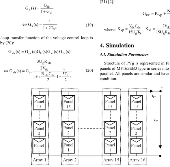
Structure of PVg is represented in Figure 10 (coupling 15 panels of MF165EB3 type in series into an array, 16 arrays in parallel. All panels are similar and have the same operational condition.
Figure 10. Coupling panels of MF165EB3 type in series and parallel.
Parameters of coupling structure are represented in Table 1.
Table 1. Parameters of coupling MF165EB3 at stc.
Type of parameters Symbol Value
Short-circuit current ISC (A) 117.76
Open-circuit voltage VOC (V) 456
Voltage at MPP Vmpp (V) 363
Current at MPP Impp (A) 109.28
Temperature coefficient of ISC CTI (%/°C) 0.057
Temperature coefficient of VOC CTV (%/°C) -0.346
Temperature coefficient of power CTP (%/°C) -0.478
Photo-generated current Iph (A) 117.79
Reverse generated current I0 (A) 1653x10-6
Thermal voltage at p-n junction Vt (V) 25.215
Series resistor RS (Ω) 0.2354
Parallel resistor Rp (Ω) 109.84
Parameters of DC/DC boost converter: Rdc= 0.1 Ω, Ldc= 0.02 H, Cpv=10-3 F.
Parameters of DCbus: Cdc=5x10⁻³ F, Vdc=804 V.
Frequency of control pulse generator: fS=50 kHz.
Parameters of transformer:
Strans=40 kVA, Rtrans= 0.00019 Ω, Ltrans = 0.884 H.
Grid: 22 kV grid, base frequency 50 Hz. Filter: Rfilter= 0.0001 Ω, Lfilter= 0.45 mH.
Parameters of G and T: G is considered in a scenario as presented in Figure 11, T=40°C.
Figure 11. The variation of G in sample scenario.
Parameters of grid-connected control system: Current controller: Kii= 1.825, Kip=0.83,
Voltage controller: Kui=66.1, Kup= 2.68.
Electric energy A(t) each second received from PVg in range time (0÷t) is calculated by (22):
0 0.5 1 1.5 2 2.5 3
800 850 900 950 1000
Thoi gian (s)
G
(
W
/m
2
t
pv 0
A(t)=
∫
p (t)dt (22)where, ppv (t) is instantaneous power generating from PVg.
Interactive power flows (active power Pinv and reactive
power Qinv between DC side and AC side of the bidirectional
DC/AC converter are defined by (23) and (24):
inv d d q q
3
P (V i V i )
2
= + (23)
inv d q q d
3
Q ( V i V i )
2
= − + (24)
4.2. Simulation Results
Simulation results for characteristic of ppv (t), A (t) and
power at MPP (Pmpp (t)) are represented in Figure 12 when
combining the IB-AVC method for the DC/DC converter and the grid-connected control system for the bidirectional DC/AC converter. Characteristic of voltage at DCbus is showed in Figure 13.
Figure 12. Characteristic of ppv (t), Pmpp (t), A (t).
Figure 13. Characteristic of voltage at DCbus.
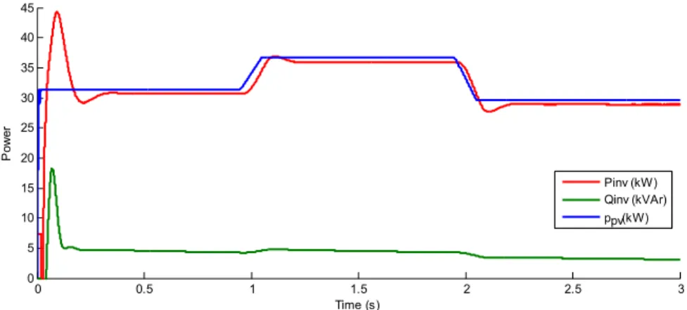
Power flows interacting with grid and exploited from PVg are demonstrated in Figure 14.
Figure 14. Power flows interacting with grid and ppv (t) characteristic.
In Figure 14, ppv (t) characteristic tracked Pmpp
characteristic immediately and exactly corresponding to the time that had change of G (ensuring dynamic ability) and maintaining the operation at MPP corresponding to the time
that didn’t have any change of G (ensuring static ability). Moreover, Figure 13 showed that the voltage at DCbus was held at a fixed value of 804V and only fluctuated at the time of changing G. These simulation results showed that
0 0.5 1 1.5 2 2.5 3
0 5 10 15 20 25 30 35 40
Time (s)
P
o
w
e
r
(k
W
)
a
n
d
e
le
c
tr
ic
e
n
e
rg
y
A
(t
)
(k
W
s
)
p (t) Pmpp(t) A(t)
A(t)=3x32.54 kWs
pv
0 0.5 1 1.5 2 2.5 3
0 200 400 600 800 1000
Time (s)
V
o
lt
a
g
e
(
V
)
Vdcref Vdc
0 0.5 1 1.5 2 2.5 3
0 5 10 15 20 25 30 35 40 45
Time (s)
P
o
w
e
r
controllers helped to exploit near all of available energy of PVg (received 97.62 kWs - corresponding with efficiency 99.9%).
At the time range from beginning to 0.13s in Figure 14, the bidirectional DC/AC converter worked as a rectifier when receiving power from the grid (Pinv<0 and Qinv<0). In this
time range, energy from the grid charged the capacitor at DC side of the bidirectional DC/AC converter and made voltage at DCbus shoot up while power from PVg continued to go
through the DC/DC converter to DCbus. After above time range, the bidirectional DC/AC converter worked as an inverter because tis capacitor discharged and power from PVg went through DC side to AC side of the bidirectional DC/AC converter to the grid (Pinv >0 and Qinv >0). Active
power flow was smaller than PV power after begining 0.35s and delayed in the time of changing G.
Current and voltage curves of A phase at 1s and 2s are represented in Figure 15 and Figure 16.
Figure 15. iinv current and uinv voltage at output of DC/AC converter at 1s.
Figure 16. iinv current and uinv voltage at output of DC/AC converter at 2s.
Wave forms of output voltage and current of the bidriectional DC/AC converter is always pure sines. Moreover, module of voltage has a fixed value while module of current is increasing or decreasing that corresponds with change of G. FFT Analysis tool showed total harmonic distorsion (THD) of iinv is 0.31% and uinv is 0.37%. These
values are less very much than rate of IEEE1547 standard (5%). Above simulation results showed that it had a good combination of the IB-AVC method and the grid-connected system in whole process exploiting energy from PVg.
5. Conclusion
This paper builds a grid-connected control system for a three-phase bidirectional DC/AC converter to exploit PVg.
By combining IB-AVC method for a DC/DC boost converter and the grid-connected control system for the bidirectional DC/AC converter, power flow goes through the power circuit of this converter in two directions to charge the capacitor at DCbus or generate power from PVg into the grid.
Parameters for voltage and current controllers are determined by using parameters of power circuit to create a stable operation for DC/DC and DC/AC converters. The grid-connected control system has two control cascaded loops (outer voltage loop, inner current loop) using information provided by a PLL to hold voltage at DCbus at a fixed value, balance power at two sides of the bidirectional DC/AC converter and synchronize to the grid under any operational condition.
Simulation results showed that the designed control system
0.9 0.92 0.94 0.96 0.98 1 1.02 1.04 1.06 1.08 1.1
-400 -300 -200 -60 0 60 200 300 400
Time (s)
O
u
tp
u
t
v
o
lt
a
g
e
a
n
d
c
u
rr
e
n
t
o
f
D
C
/A
C
c
o
n
v
e
rt
e
r
A-phase voltage (V) A-phase current (A)
1.9 1.92 1.94 1.96 1.98 2 2.02 2.04 2.06 2.08 2.1
-400 -300 -200 -60 0 60 200 300 400
Time (s)
O
u
tp
u
t
v
o
lt
a
g
e
a
n
d
c
u
rr
e
n
t
o
f
D
C
/A
C
c
o
n
v
e
rt
e
r
adapted to execute all requirements for a grid-connected system. It helped to exploit power at MPP at any value of (G, T) and generate it to the grid, provide low value of THD for voltage and current waves at PCC. Because of being mainly affected by G, this paper only simulated at a scenario of G and a fixed value of T but simulation results could show that current amplitude also changed with the change of G while voltage amplitude was held at a fixed value (peak value is 400V). Moreover, output current and voltage waves were always in sine form. These results prove the correctness of the designed control system and can apply it under real condition.
References
[1] Antonino Riccobono, Enrico Santi (2011), “Positive Feed-Forward Control of Three-Phase Voltage Source Inverter for DC Input Bus Stabilization”, Applied Power Electronics Conference and Exposition (APEC), 2011 Twenty-Sixth Annual IEEE.
[2] Behrooz Bahrani, Stephan Kenzelmann, Alfred Rufer (July 2011), “Multivariable-PI-Based dq Current With Superior Axis Decoupling Capability”, IEEE Transactions on Industrial Electronics, Vol. 58, No. 7.
[3] H. A. Pereira, A. F. Cupertino, C. A da S. G. Ribeiro and S. R. Silva (2013), “Influence of PLL in Wind Parks Harmonic Emissions”, IEEE PES Conference On Innovative Smart Grid Technologies Latin America.
[4] Hadi Malek (2014), “Control of Grid-connected Photovoltaic Systems Using Fractional Order Operators”, A dissertation of Doctor of Philosophy, Utah State University.
[5] Jasim Farhood Sultani (2013), “Modelling, Design and Implementation of d-q Control in Single-phase Grid-connected Inverters”, Dissertation for degree of Doctor of Philosophy, De Montfort University, Leicester, UK.
[6] Jin-Wu Gong, Bai-Feng Chen, Pei Li, Fei Liu, Xiao-Ming Zha (2009), “Feedback Decoupling and Distortion Correction Based Reactive Compensation Control for Single-phase Inverter”, IEEE International Conference on Power Electronics and Drive Systems, Taiwan.
[7] Le Tien Phong, Ngo Duc Minh, Nguyen Van Lien (2017), Improving Efficiency and Response of Photovoltaic Power Generation with DC-DC Buck Converter, International Journal of Engineering Research & Technology (IJERT), ISSN: 2278-0181, Vol. 6 Issue 03.
[8] Marcelo Gradella Villalva, Thais Gama de Siqueira, Marcos Fernando Espindola, Ernesto Ruppert (2009), “Modeling and Control of a Three-phase Isolated Grid-connected Converter for Photovoltaic Application”, IEEE Power Electronics Conference, Brazil.
[9] Md. Parvez Akter, Saad Mekhilef, Nadia Mei Lin Tan, Hirofumi Akagi (2015), “Model Predictive Control of
Bidirectional AC-DC Converter for Energy Storage System”, Journal of Electrical Engineering Technology, No. 10, ISSN 2093-7423.
[10] Mirjana Milosevic, Goran Anderson, Stevan Grabic (2006), “Decoupling Current Control and Maximum Power Point Control in Small Power Network with Photovoltaic Source”,
2006 IEEE PES Power Systems Conference an Exposition, pp 1005-1011.
[11] Muhammad H. Rashid, “Power electronics handbook”,
Academic Press, International Standard Book Number: 0-12-581650-2, 2001.
[12] S. Lakshmi Devi, K. Sudheer (2014), “Modelling and Co-ordination Control of Hybrid Grid”, International Journal of Computer Science and Network Security, Vol. 14, No. 10.
[13] Suzan Zeynep Eren (2008), “Modifying the Three-phase Synchronous Reference Frame Phase-locked Loop to Remove Unbalance and Harmonic Errors”, A thesis for the Degree of Master of Science, Queen’s University, Kingston, Ontario, Canada.
[14] Tatjana Kalitjuka (2011), “Control of Voltage Source Converters for Power System Applications”, Master of Science in Electric Power Engineering, Norwegian University of Science and Technology.
[15] Teresa Orłowska-Kowalska, Frede Blaabjerg, José Rodríguez (2014), “Advanced and Intelligent Control in Power Electronics and Drives”, Springer Publisher, Volume 531, ISBN 978-3-319-03401-0.
[16] Yu Zhang (2011), “Small-Signal Modeling and Analysis of Parallel-Connected Power Converter Systems for Distributed Energy Resources”, Dissertation for degree of Doctor of Philosophy, University of Miami.
Biography
Le Tien Phong, born in 1982, received the M. Sc. degree in 2010 in Electrical Engineering from Ha Noi University of Technology and Science and working in Thai Nguyen University of Technolgy now. Interested research fields: renewable energy, control electrical energy conversions, FACTS.