Contents
Description Page
Instructions for Eaton 7.2kV AMPGARD
Arc Resistant Motor Control Centers
1. Introduction . . . 2
2. Receiving, Handling, and Storing . . . 4
3. Installation . . . 5
4. Plenum and Duct Installation . . . 10 5. Description of Arc Resistant Ampgard MVC . 15
Read and understand these instructions before attempting installa-tion, operainstalla-tion, or maintenance of this equipment. This equipment must be installed and serviced only by qualified electrical personnel. Retain this document for future use.
D
D
WARNING
HAZARDDOFDELECTRICALDSHOCKDORDBURN.DDOPERATINGDTHEDEQUIPMENTD OUTSIDEDOFDITSDRATINGSDMAYDCAUSEDFAILUREDRESULTINGDINDPROPERTYD DAMAGE,DSEVEREDPERSONALDINJURY,DORDDEATH.DDTHEDEQUIPMENTDMUSTD BEDOPERATEDDWITHINDITSDNAMEPLATEDRATINGS.D
D
DANGER
ALLDAPPLICABLEDSAFETYDCODES,DSAFETYDSTANDARDS,DANDDSAFETYDREG- ULATIONSDMUSTDBEDSTRICTLYDADHEREDDTODWHENDINSTALLING,DOPERAT-ING,DORDMAINTAININGDTHISDEQUIPMENT.Table 1. AMPGARD Electrical Ratings
RatedDD Maximum Voltage
RatingsDperDULD347
StartersDperDD
structure StarterDDFrameDSize
MaximumD CurrentDperD starter InsulationDLevel RatedDMainDD BusDD ContinuousDD Current RatedDShortDTimeD Short-CircuitD CurrentDWithstandD (2Dsecond) DielectricDWithstand LightningDImpulse
kVDrms # Amperes Amperes kVDrms kVDpeak Amperes kADrmsDSym
7.2 1 400 350 18.2 60 1000, 1200, 2000, 3000 50 7.2 2 400 320 bottom320 top 18.2 60 1000, 1200, 2000, 3000 50 7.2 2 400 350 bottom210 top 18.2 60 1000, 1200, 2000, 3000 50 7.2 1 800 600 18.2 60 1000, 1200, 2000, 3000 50
Section 1: Introduction
1.1 PurposeThis instruction bulletin covers the installation of the plenum and operation of AMPGARD arc resistant medium voltage motor control centers. It does not cover all possible contingencies, variations, and details that may arise during installation of this equipment.
1.2 Application and Description
Eaton’s AMPGARD arc resistant Medium Voltage Control (MVC) pro-vides centralized control and protection of medium voltage power equipment and circuits in industrial, commercial, and utility installa-tions involving motors, transformers, and feeder circuits. Arc resis-tant MVC provides additional protection in the event of an internal arcing fault. Eaton’s arc resistant equipment meets or exceeds UL 347 and UL 50E as they apply to metal-enclosed medium voltage industrial equipment and ANSI/IEEE C37.20.7 for arc resistant type 2B. The assemblies also exceed all seismic requirements contained in the International Building Code and the California Building Code. See Table 2 for arc ratings.
Table 2. AMPGARD Arc Resistant Ratings RatingsDperDIEEEDC37.20.7 PlenumDandDDuctDStyle AccessibilityD Type RatedD ArcDShortD CircuitD WithstandD
Current RatedDArcDDuration kADrmsD
Sym sec.
2B 30 0.5 original
2B 49 0.5 common with VacClad
2B 50 0.5 original
1.3 Documentation Reference
Refer also to the following instructions to install the plenum and exhaust ducts on arc resistant equipment:
IB 48077: Plenum and Duct Installation
These instructions cover aspects of the equipment particular to its arc resistant enclosure. This document must be used in conjunction with the following instructions specific to the type of starter being installed:
IB48041: AMPGARD 400A Motor Starters (not arc resistant) IB48043: AMPGARD 800A Motor Starters (not arc resistant) IB48068: AMPGARD RVSS Soft Starters
You may also wish to refer to one of the following documents: IB48042: AMPGARD Seismic Instructions
IB02201001E : VCP-W Arc Resistant Switchgear
For further information on installation and application, refer to the applicable technical data, publications, and/or industry standards. Download Eaton electronic information from
www.eaton.com/electrical.
1.4 Eaton Contact Information
For the location of your nearest Eaton sales office or distributor, call toll-free 1-800-525-2000 or log onto www.eaton.com/electrical. Eaton Services and Systems (EESS) can be reached at 1-800-498-2678.
1.5 Modifications to Equipment
Any modifications to the equipment outside of the assembly instruc-tions in Eaton documentation compromises compliance with ANSI/ IEEE C37.20.7. Please contact the factory with any related ques-tions.
MODIFICATIONS TO THE EQUIPMENT ENCLOSURE CAN COMPROMISE ITS ARC RESISTANT PROPERTIES. Low Voltage Doors are the only parts that may be modified in an arc resistant lineup. Medium voltage cell doors, side covers, or rear covers must not be modified.
1.6 Safety Precautions
Only qualified electrical personnel with training and experi-ence on high-voltage apparatus shall be permitted to work on this equipment. They shall be familiar with the work to be performed, as well as industry and local safety procedures and standards.
1. Read and understand these instructions before attempting instal-lation, operation, or maintenance of the equipment.
2. Disconnect all low voltage and medium voltage power sources before working on the equipment per Occupational Safety and Health Act (OSHA) and lockout procedures. Verify that the volt-age has been removed. Observe National Electrical Code (NEC), OSHA, and local procedures and standards. This includes visual inspections while the door is open, making any adjustments inside or outside the enclosure, performing maintenance, or installing replacement parts.
3. Never leave the isolation switch in an intermediate position. Always move the handle to the fully open or fully closed position. 4. The user is responsible for conforming to all applicable code
requirements with respect to grounding the equipment. 5. Use adequate fall protection when working above ground level.
D
D
CAUTION
THEDARCDRESISTANTDRATINGDOFDTHEDEQUIPMENTDISDONLYDVALIDDWHEND ALLDCOVERSDANDDDOORSDAREDPROPERLYDSECUREDD(EXCEPTDFORDLOWD VOLTAGEDDOORS)DOVERDTHEDENTIREDLENGTHDOFDANYDGIVENDLINEUP.DD WHENDWORKINGDINSIDEDADMEDIUMDVOLTAGEDCOMPARTMENT,DEVEND THOUGHDTHEDCOMPARTMENTDISDISOLATEDDELECTRICALLY,DPERSONNELD WILLDNOTDBEDPROTECTEDDAGAINSTDANDARCDFAULTDANDDMUSTDWEARD APPROPRIATEDPPE.D
D
CAUTION
BEFOREDENERGIZINGDTHEDEQUIPMENT,DENSUREDTHAT:D •D THEDEQUIPMENTDISDSECUREDDONDADTRUEDANDDLEVELDSURFACE.D •D CONFIRMDALLDHARDWAREDISDINDPLACEDANDDTORQUEDDPERDSPECIFIEDDD D VALUES.D •D CONFIRMDNODTOOLSDORDOBJECTSDAREDLEFTDINSIDEDTHEDENCLOSURED •D CONFIRMDALLDDEVICES,DCOVERS,DDOORS,DPANELS,DETC.,DAREDSECURED. 1.7 Sound LevelsThe sound developed during an arc fault event is significant and is not completely predictable due to the nature of the arc fault. Sound is dramatically affected by surrounding structures, buildings, and equipment, so testing can’t be done for all possible circumstances. Sound levels were measured at various distances from the end of a 2-meter-long duct during 50kA arc fault events, and used to generate the guidelines tabulated below. Please review the table and deter-mine the correct PPE required by personnel in the vicinity of the equipment for your installation.
Table 3. Sound Pressure Levels (SPL)
DistanceDfromDendDofDductD(ft.) 0 50 100 200
MinimumDexpectedDSPLD(dB) 120 110 100 100
Section 2: Receiving, Handling, and Storing
AMPGARD Equipment
2.1 Receiving
The equipment is shipped assembled in shipping splits. Depending on the length of the lineup, it may be necessary to ship the equip-ment in several shipping sections to facilitate handling.
Each shipping section ships bolted to wooden skids and covered with protective material. A box labeled “Installation Parts” is also included. This box contains the packing list. The packing list identifies all cartons and crates. Each carton and crate is labeled with the shop order number and a shipping weight.
Accept items from shipping carrier if all items described on the pack-ing list have been received. If the equipment has been damaged, file a claim as soon as possible with the carrier and notify the nearest Eaton representative.
If the plenum and duct are to be installed upon receipt, unpack and handle according to Section 2.2. If the plenum and duct are to be stored, see Section 2.3.
2.2 Handling
Refer to Table 4 for the approximate weights of the various AMPGARD equipment configurations.
Table 4. Typical Section Weights
EquipmentDType
ArcDResistantDRating
MainDBusDRating 30DkA 50DkA 49DkA
Amperes LbsD(kg) LbsD(kg) LbsD(kg)
2-high 400A starter 36in. (915mm) wide 1000 1200 2000 3000 1630 (740.9) 1640 (745.5) 1650 (750) 1670 (759.1) 1680 (763.6) 1690 (768.2) 1700 (772.7) 1720 (781.8) 1680 (763.6) 1690 (768.2) 1700 (772.7) 1720 (781.8) 1-high 800A starter
36in. (915mm) wide 1000 1200 2000 3000 1580 (718.2) 1590 (722.7) 1600 (727.3) 1620 (736.4) 1630 (740.9) 1640 (745.5) 1650 (750) 1670 (759.1) 1630 (740.9) 1640 (745.5) 1650 (750) 1670 (759.1) Incoming Line 24in. (610mm) wide 1000 1200 2000 3000 1090 (495.5) 1090 (495.5) 1100 (500) 1110 (504.5) 1140 (518.2) 1140 (518.2) 1150 (522.7) 1160 (527.3) 1140 (518.2) 1140 (518.2) 1150 (522.7) 1160 (527.3) Arc plenum lineup
per 1 in. (25mm) of
width n/a 5.6 (2.5) 6 (2.7) 4.2 (1.9)
Exhaust duct per
1 in. (25 mm) of length n/a 5 (2.3) 6.4 (2.9) 1.7 (0.8) Dual-exhaust manifold n/a n/a n/a 150 (68.2) Transition section to
VacClad Switchgear
4in. (100mm) wide n/a 30 (13.6) 30 (13.6) 162 (73.6) The preferred method of lifting and maneuvering the shipping sec-tions into their final position is with an overhead crane. Lifting members are bolted to the top of each shipping section. Attach a bridle sling to all 4 lifting points to lift or move the section. Refer to 25A4312H01, included with each shipping section for handling instructions. After the section has been moved into installation posi-tion, remove the lifting members and discard them.
If a crane is not available, safeguards need to be put in place to assure that the equipment is not deformed during maneuvering. Move the shipping section by use of rollers.
2.3 Storing Indoor Equipment
AMPGARD equipment contains insulating materials, electrical con-tacts, and operating mechanisms which must be protected against dirt, moisture, dust, foreign materials, corrosive atmospheres, and extreme temperature changes. If it is necessary to store the equip-ment before installation, place the equipequip-ment on a true and level surface in order to reduce strain and distortion in the equipment. Cover it and keep it in a clean and dry location with ample air circula-tion and heat to prevent condensacircula-tion.
otee:
N Storing the equipment outdoors is not recommended.
Section 3: Installation
3.1 Installation Procedure
To install AMPGARD arc resistant equipment, first follow the instal-lation instructions outlined in IB48041 or IB48043. Refer to the fol-lowing figures and tables for information specific to the arc resistant product:
otee:
N The hinged exhaust flaps on top of the equipment are secured with screws in tear-away slots. These screws are intended to remain in place and should not be removed.
Figure 1. Bus Enclosure Flap Screws - Do Not Remove. Table 5. Fastener Torque Requirements
Bolt size in mm 0.25 (6.35) 0.31 (7.87) 0.38 (9.65) 0.50 (12.7) 0.62 (15.75)
BoltDMaterial TorqueDinDFoot-PoundsD(N-m)
High Strength Steel 5 (6.78) 12 (16.27) 20 (27.12) 50 (67.8) 95 (128.82)
Table 6. Minimum Installation Clearances
ArcD
Rating ExhaustDDuctDConfigurations
MinimumDclearanceDtoDobstructionsD(in)
MinimumD ceilingD heightD(in)
Non-seismic Seismic
Size Rear Sides Rear
30 kA Open Top 40 (1016) 40 (1016) 40 (1016) 40 (1016) 144 (3658) Side, Front, Rear 4 (102) 4 (102) 6 (152) 6 (152) 124 (3150) 50 kA Open Top 80 (2032) 80 (2032) 80 (2032) 80 (2032) 144 (3658) Side, Front, Rear 4 (102) 4 (102) 6 (152) 6 (152) 124 (3150) 49 kA Side, Front, Rear 3 (76) 3 (76) 6 (152) 6 (152) 146 (3708)
Figure 2. Footprint and lag-down bolt locations. 4.5 114 15.0381 9.0229 27.0686 4.5114 4.5 114 15.0381 4.5 114 4.5114 27.0 686 4.5114 21.7 551 2.2 56 A 28.0 712 1.0 25 2.8 72 6.3 161 24" section 36" section Only one Required ArcDD Rating inchesD(mm)A 30 (280)11.0 49 50 (533)21.0
Figure 3. 49 kA Front View.
Single Exhaust Exit, out Front
Dual-exhaust Manifold, out Right End
109.6 2783 Height from floor
to centerline of front / rear exhaust duct
127.7 3244 Height from floor
to highest point on plenum
1.4 35
Distance from edge of equipment footprint to bus compartment end cover 95.3
2420 Height from floor
to top of bus compartment
18.0 456 Centerline of front / rear exhaust duct centered on equipment footprint 24.2 615 Duct collar outside width 24.20 615 Duct collar outside height 16.9 428 Varies with length of duct collar chosen Dimensioning: 4.0 inches 101 millimeters
Figure 4. 49 kA Side View.
Single Exhaust Duct, out End
Dual-exhaust Manifold, out End
109.6 2784 Centerline of side exhaust duct 127.7 3244 Highest point on plenum 24.6 626 Centerline of side exhaust duct to front of footprint 25.3 643 Centerline of side exhaust duct to rear of footprint 1.2 29
Rear cover brace to rear edge of footprint .9
22
Rear edge of bus compartment to rear of footprint 1.6 40 Edge of bus compartment to front of footprint 10.0 254 10.0 254 14.3 364 Duct centerline to top of bus compartment 40.6 1032 Distance between duct centerlines 5.9 150 Duct centerline to front edge of bus compartment
5.8 148 Duct centerline to
rear edge of bus compartment
Dimensioning:
4.0 inches 101 millimeters
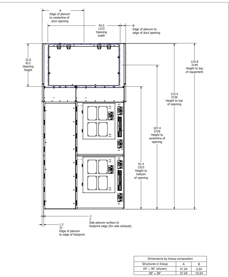
Figure 5. 30 kA/ 50 kA Front View.
Dimensions by lineup composition Structures in lineup A B 24" + 36" (shown) 31.24 4.24 36" + 36" 37.24 10.24
Figure 6. 50 kA Side View. 93.28 2369.3 Height to top of bus compartment
3.2 Close-coupling AMPGARD MVC and Eaton Switchgear AMPGARD arc resistant MVC can be close-coupled to arc resistant VacClad switchgear in a single lineup. For these configurations, the AMPGARD section which is adjacent to the switchgear will be provided with a 4” wide filler section attached. When installing the lineup, the AMPGARD section must be attached to the switchgear BEFORE plenums are installed. Follow these instructions for cou-pling the AMPGARD lineup to the Switchgear.
1. Position the AMPGARD lineup next to the Switchgear, lining up the threaded holes in the AMPGARD filler section with the mat-ing holes in the side sheet of the switchgear.
2. Ensure the two structures are level relative to each other and are mated together firmly. From inside the switchgear section, the threaded holes in the AMPGARD filler should be clearly visible and well-aligned.
D
D
WARNING
ENSUREDTHATDTHEDCLOSE-COUPLEDDSECTIONSDAREDADEQUATELYDALIGNEDD ANDDLEVELEDDTODEACHDOTHERDBEFOREDINSTALLINGDMATINGDHARDWARE.DD DODNOTDUSEDTHEDMATINGDHARDWAREDTOD“JACK”DTHEDEQUIPMENTDINTOD POSITION.DDTHISDCANDCAUSEDANDOVER-STRESSEDDCONNECTION,DWHICHD MAYDREDUCEDARC-RESISTANTDCAPABILITIESDOFDTHEDEQUIPMENT.3. Install 3/8” hardware with lock washers and 3/8” extra-wide (1.5” O.D.) feider washers into each of the threaded holes, 12 places total. Torque per Table 5.
Figure 7. AMPGARD with 4” filler for close-coupling to VacClad. 3.3 Seismic Installations
For seismic rated equipment, refer to Eaton drawing 25A4254 for additional instructions on mounting in these special locations. It is the user’s responsibility to insure the mounting pad is sufficiently strong to properly anchor and support the equipment.
3.4 Adjustments
Each controller is properly adjusted at the factory before shipment. However, vibration and mechanical stresses imposed by transit and installation can adversely affect mechanical interlocks and other adjustments; therefore, a final inspection is essential before energiz-ing. If this inspection reveals any portion of the controller has come out of adjustment, the controller should be re-adjusted according to information in the instruction book or by a qualified Eaton service engineer.
Section 4: Plenum and Duct Installation
AMPGARD arc resistant equipment is only complete when a plenum and arc exhaust system (typically ducts) are correctly installed. 4.1 Access to equipment
Installation of plenums and ductwork requires access to all sides of the equipment. If access to the back and sides would be restricted in the final location, this installation should be done before perma-nently installing the lineup. 18” of clearance above the finished ple-num (144” from ground) is recommended for ease of installation. 4.2 Installation
There are two different styles of arc plenum and duct used on the AMPGARD AR product. They are delivered in a partially-assembled state, and are easily distinguished from each other by comparing their construction. Refer to the figures below to determine if you will be installing the 49kA style or the 30/50kA style.
Installing the plenums will obscure access to the main bus. Before installing any plenum or duct, ensure the MVC equipment is bolted in place and all bus splices are complete.
4.2.1 49kA style plenum installation
Installation instructions for this style plenum and duct are found in IB 48077.
Figure 8. Identifying Plenum Stylee: 49kA.
4.2.2. 30/50kA style plenum installation
Figure 9. Identifying Plenum Style 30-50kA. 4.2.2.1 30/50kA style Plenum Installation
1. For any 24” wide sections with top-entry incoming-line cabling, a conduit must be installed to house the cables. This must be done before installing any plenum or duct parts.
plenum duct section
duct section
plenum
Figure 10. 30/50kA 24” wide sections.
a. Attach both of the conduit parts to the top of the main bus compartment with ¼” fasteners
b. Secure the conduit parts to each other with ¼” fasteners. c. REMEMBER to install 1/4” cage nuts into the square holes on
the top of the conduit. These will be needed at the end, to secure the conduit to the top panels, and are difficult to install at that step!
2. For any 36” wide sections with top-entry line or load cabling, a conduit must be installed to house the cables. This should be done before installing any plenum or duct parts.
Figure 11. 30/50kA 36” wide sections.
a. Attach both of the conduit parts to the top of the main bus compartment with ¼” fasteners
b. Secure the conduit parts to each other with ¼” fasteners. c. REMEMBER to install 1/4” cage nuts into the square holes on
the top of the conduit. These will be needed at the end, to secure the conduit to the top panels, and are difficult to install at that point!
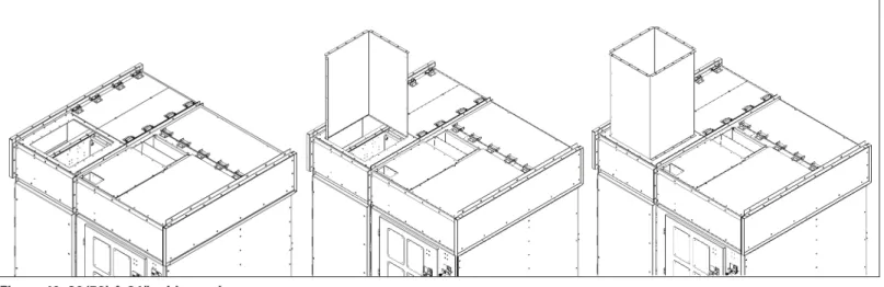
3. Start installing the plenums. Plenum sections are pre-assembled at the factory and shipped in assemblies to match the shipping splits of the equipment. Refer to the drawings for the location that each plenum assembly should be installed.
4. Using a crane or fork truck, lift the first plenum assembly into position on top of the MVC equipment.
Figure 12. Installing Plenum Assembly.
5. Secure the plenum assembly around its entire perimeter with 5/16” fasteners as shown in Figure 12. Every bolt must have a lockwasher and a flat washer. Every nut must have a flat washer. 6. Install the conduit cover plates over all top-entry conduits using
¼” fasteners.
7. On the last plenum section installed, 2 bolts on each verti-cal flange will be protruding at the open end of the assembly. Remove these and set aside to prevent interference when install-ing the next plenum assembly.
8. Proceed to install the next plenum assembly as with the previous one.
9. Secure the new plenum assembly to the top of the equipment as above, next to the previous one.
10. Connect the vertical flanges of the adjacent plenum assemblies together, installing 30” long flat and angled seam covers as shown below. Use 5/16” fasteners with flat and lock washers.
Figure 13. Installing Vertical Seam Covers.
11. Connect the top horizontal flanges of the adjacent plenum assemblies, installing two long angled seam covers as shown below. Use 5/16” fasteners with flat and lock washers. For 30kA equipment seam covers will be 40” long. For 50kA equipment seam covers will be 50” long.
Figure 14. Installing Horizontal Seam Covers.
12. Install top entry conduit covers as required on the new section of plenum.
13. Continue adding plenum assembly sections in this fashion until the plenum for the entire lineup is complete.
4.2.2.2 Front- or Rear-exiting Exhaust Duct
1. A lineup which has the exhaust duct exiting from the front or the rear requires that two adjacent sections be selected for the duct to exit over. They can either both be 36” wide or one can be 24” and the other 36” wide. A duct adapter sheet is used instead of plenum front/rear covers over those two structures. The duct sections can then be bolted to the opening in this cover, as they are for a side-vented configuration. Flame baffles are not required at the connection between the duct and the adapter sheet.
Figure 15. Front Exhaust Adapter. angled seam cover flat seam cover long angled seam covers
The two sections over which the duct exhausts must have the correct orientation of hinges for the exhaust flaps. This only applies to the structures which have a duct installed above them; other structures in the lineup do not have this requirement. Refer to Figures 16 and 17 for correct hinge location.
Figure 16. Front Exhaust Flap Hinge Location.
Figure 17. Rear Exhaust Flap Hinge Location.
4.2.2.3 30 / 50 kA style Duct Installation
1. In a side-vented configuration, ensure that a support angle is installed at the bottom edge of the plenum where the duct will attach. The angle should have 5/16“ cage nuts installed in the square holes. If this part is missing, contact the factory for a replacement.
Figure 18. Side Vent Support Angle.
2. Lift and position the exhaust duct sections according to the job layout. Secure duct sections in place following the same pro-cedure used for plenum sections, installing seam covers at all vertical and horizontal seams. Make sure the horizontal seams beneath the duct sections also have covers.
3. Support the duct sections as they are installed per layout draw-ings. The minimum unsupported distance is 78 in. (2000 mm).
Figure 19. One Duct Section Installed.
support angle
Figure 20. Two Duct Sections Installed.
4. The last section of duct has an exhaust flap installed. Ensure the flap can open freely, without obstruction. Check that the 4 bolts which protrude from the end of the duct section are installed with the bolt heads facing away from the duct. If the bolts are installed the opposite way, the shaft may catch on the exhaust flap clearance hole.
Figure 21. Exhaust Duct with End Flap.
5. Fasten the exhaust flap closed with the provided plastic push-in clips.
Figure 22. Duct end Bolts.
Correct
Section 5: Description of Arc Resistant
AMPGARD MVC
Arc resistant Medium Voltage Control is tested for resistance to the effects of arcing due to an internal fault. The occurrence of arcing inside motor controllers produces a variety of physical phenomena. For example, the arc energy resulting from an arc developed in air at atmospheric pressure will cause a sudden pressure increase inside the enclosure and localized overheating. This results in both severe mechanical and thermal stresses on the equipment. Moreover, the materials involved in or exposed to the arc may produce hot decom-position products, either gaseous or particulate, which may be dis-charged to the outside of the enclosure.
IEEE guide C37.20.7 and EEMAC standard G14-1, 1987, provide pro-cedures for testing the resistance of metal-clad and metal-enclosed medium voltage switchgear under conditions of arcing due to an internal fault. The arc resistant switchgear is classified by accessibil-ity types in the two documents as follows.
IEEE C37.20.7, 2001 – Guide for Testing Medium-Voltage Metal-Enclosed Switchgear for Internal Arcing Faults
• Accessibility Type 1
Switchgear with arc resistant designs or features at the freely accessible front of the equipment only.
• Accessibility Type 2
Switchgear with arc resistant designs or features at the freely accessible exterior (front, back, and sides) of the equipment only. Type 2B
Switchgear with arc resistant features inside control compart-ments in addition to the Type 2 requirecompart-ments.
The IEEE standard defines internal arcing short-circuit current as the maximum value of the RMS symmetrical prospective current applied to the equipment under conditions of an arcing fault for the arcing duration specified by the manufacturer. The preferred value of the internal arcing short-circuit current is the rated short-time current of the equipment. The preferred arcing duration is indicated as 0.5 sec at the rated power frequency of the equipment.
A single test is done to verify resistance of switchgear against pressure as well as burn through. The actual values (which may be higher or lower than the preferred values) of the internal short-circuit current and arcing duration are specified by the manufacturer on the equipment ratings nameplate.
Arc resistant features are intended to provide an additional degree of protection to the personnel performing normal operating duties in close proximity to the equipment while the equipment is operating under normal conditions. Several conditions must be met for the equipment to perform as required. These conditions are considered normal operating conditions for proper application of arc resistant switchgear designs and are as follows:
1. All doors and covers providing access to high-voltage components are properly closed and latched.
2. A plenum and duct assembly is properly installed on top of the switchgear, when applicable.
3. Pressure relief devices are free to operate.
4. The fault energy available to the equipment does not exceed the rating of the equipment (short-circuit current and duration). 5. There are no obstructions around the equipment that could direct
the arc fault products into an area intended to be protected. 6. The equipment is properly grounded.
The arc resistant rating of this equipment is only valid when all Medium-voltage compartment doors are closed and fully latched. The rating is valid with only the Low-voltage compartment door open. The equipment may be used without additional personal pro-tective equipment where the fault level and the fault duration are within the equipment ratings. When coupled with other protective schemes, selected to operate within the rated duration of the equip-ment, the damaging effects of the arcing fault associated with fault duration can be minimized.
Eaton Corporation Electrical Sector 1111 Superior Ave. Cleveland, OH 44114 United States 877-ETN-CARE (877-386-2273) Eaton.com © 2011 Eaton Corporation All Rights Reserved Printed in USA
Publication No. IB48076 / TBG000584 August 2011
Eaton is a registered trademark of Eaton Corporation.
All other trademarks are property of their respective owners.
The instructions for installation, testing, maintenance, or repair herein are provided for the use of the product in general commercial applications and may not be appropriate for use in nuclear applica-tions. Additional instructions may be available upon specific request to replace, amend, or supplement these instructions to qualify them for use with the product in safety-related applications in a nuclear facility.
The information, recommendations, descriptions, and safety nota-tions in this document are based on Eaton’s experience and judg-ment with respect to Retrofitting of Power Breakers. This instruction-al literature is published solely for information purposes and should not be considered all-inclusive. If further information is required, you should consult an authorized Eaton sales representative.
The sale of the product shown in this literature is subject to the terms and conditions outlined in appropriate Eaton selling policies or other contractual agreement between the parties. This literature is not intended to and does not enlarge or add to any such contract. The sole source governing the rights and remedies of any purchaser of this equipment is the contract between the purchaser and Eaton. NO WARRANTIES, EXPRESSED OR IMPLIED, INCLUDING WARRANTIES OF FITNESS FOR A PARTICULAR PURPOSE OR MERCHANTABILITY, OR WARRANTIES ARISING FROM COURSE OF DEALING OR USAGE OF TRADE, ARE MADE REGARDING THE INFORMATION, RECOMMENDATIONS, AND DESCRIPTIONS CONTAINED HEREIN. In no event will Eaton be responsible to the purchaser or user in contract, in tort (including negligence), strict liability or otherwise for any special, indirect, incidental or conse-quential damage or loss whatsoever, including but not limited to damage or loss of use of equipment, plant or power system, cost of capital, loss of power, additional expenses in the use of existing power facilities, or claims against the purchaser or user by its cus-tomers resulting from the use of the information, recommendations and description contained herein.