IP-based Access Network Infrastructure for
Next Generation Wireless Data Networks
R. Ramjee, T. La Porta, L. Salgarelli, S. Thuel, K. Varadhan
Bell Labs, Lucent Technologies
Holmdel, NJ
ramjee,tlp,lsalgarelli,thuel,[email protected]
L. Li
Dept of CS
Cornell University
[email protected]
AbstractNext generation wireless network standards are currently being defined. The access network architectures have several specialized components tailored for their respective wireless link technologies even though the services provided by these different wireless networks are fairly similar. In this paper, we propose a homogeneous IP-based network as a common access network for the different wireless technologies. The IP-IP-based access network uses the internet standard, Mobile IP, for supporting macro-mobility of mobile hosts and HAWAII for supporting micro-mobility and paging functionality of current wireless networks. We also illustrate how the proposed IP-based solution can interwork with existing infrastructure so that deployment can be incremental.
Keywords: Wireless Networks, Mobile IP
1
Introduction
Traffic on the Internet is growing exponentially due to increased subscriber base and new applications. Wide area wireless networks are also experiencing rapid growth in terms of subscribers. Currently, there are many efforts underway to provide data services on wireless access networks.
The Internet Protocol (IP) is the dominant internetworking protocol in operation today. The logical choice for a networking protocol for wireless data networks is also IP for several reasons. First, by using an IP-based network, applications written for wired data networks can operate on wireless networks. Second, to defray cost, integrated wireless and wireline networks can be built and managed. Third, advances on IP technology, such as IP telephony and Quality of Service (QoS), may be directly applied
to the wireless networks. This will enable wireless networks based on IP to provide voice service as well as data services, thus allowing them to tap into the vast subscriber base of cellular voice customers.
We believe all mobility-related functionality should be handled at the IP (network) layer. This enables the deployment of a homogeneous, IP-based wireless access network that is independent of the different wireless interfaces. Only wireless link specific processing is relegated to the base stations. We achieve this by extending the IP layer software running in routers and base stations in the access network.
We adopt a domain-based division of the IP mobility protocols. One of the motivations for our domain-based approach hinges on the assumption that most mobility is local to a domain. In partic-ular, most user mobility is typically contained within an administrative domain of the network. Since an administrative domain is under the control of a single authority, it is possible to incorporate spe-cial support for mobility in the infrastructure. This domain-based management approach is similar to the division of existing routing protocols into intra-domain routing protocols such as RIP or OSPF and inter-domain routing protocols such as BGP. Another recent solution for mobility management, Cellular IP [11], also adopts a domain-based approach. However, while network elements in the Cellular IP do-main are specialized for mobility management, our solution augments regular IP routers with mobility support so that these routers can also be used to route other wired IP traffic as well.
In this paper, we present the design of an IP-based access network infrastructure for next generation wireless networks. In the access network, we use the internet standard, Mobile IP, as the inter-domain protocol for supporting macro-mobility; we use an extension of Mobile IP, called HAWAII, as the intra-domain protocol for supporting micro-mobility and paging functionalities. The HAWAII protocol results in less disruption to user traffic during handoff and fewer updates to the home agent compared to Mobile IP. HAWAII’s paging support allows for efficient battery consumption at the mobile host. Furthermore, since HAWAII allows mobile hosts to retain their network address while moving within a domain, Qual-ity of Service support is simplified. Finally, we also illustrate how the proposed IP-based solution can
interwork with existing wireless infrastructure for incremental deployment.
The remainder of the paper is organized as follows. In Section 2, we overview the architectures of emerging wide-area wireless data networks, illustrating architectures from both European and North American standards. In Section 3, we present an IP-based wireless access network architecture using Mobile IP and HAWAII, an enhancement of Mobile IP. In Section 4, we compare the performance of HAWAII with Mobile IP. In Section 5, we illustrate how our IP-based architecture can be part of the next generation wide-area wireless data network architecture. In Section 6, we present our conclusions.
2
Emerging Wireless Data Network Architectures
In this section, we overview two wireless data network architectures currently being defined.
2.1
GPRS
BTS/ BSC
BTS: Base Transceiver System MD: Mobile Device
BSC: Base Station Controller
SGSN: Serving GPRS Service Node GGSN: Gateway GPRS Service Node HLR: Home Location Register VLR: Visitor Location Register
VLR HLR MD BTS/ BSC SGSN SGSN GGSN INTERNET GPRS BACKBONE NETWORK Link Layer Mobility GPRS Mobility
SS7
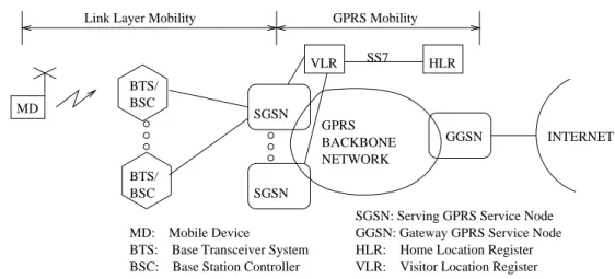
Figure 1: GPRS
General Packet Radio Service (GPRS) [2] is being defined by ETSI to provide packet data service using GSM cellular networks. A high level diagram for a GPRS network is shown in Figure 1. GPRS uses a combination of link layer and newly defined higher layer techniques for mobility management.
On the air interface, GPRS supports registration, authentication, paging, and handoff (called cell reselection), as well as procedures for channel access to transmit data packets. GPRS allows the mobile host to operate in two distinct states - an active state where the network knows the location of the mobile host’s current base station, and a standby state where the network knows only the approximate location of the user, such as a set of base stations, called the paging area, in which the mobile host resides. One of the motivations for defining the standby state is for reducing the host’s battery power consumption by allowing the mobile host to only notify the network when it moves out of the paging area. If data packets for a mobile host in standby state arrive into the wireless access network, the Serving GPRS Service Node (SGSN) ”pages” the mobile host in its paging area to determine the mobile host’s current base station before delivering the data packets.
In the backbone network, GPRS defines a new tunneling protocol built on top of an IP network, called Generic Tunneling Protocol (GTP), to handle device mobility, and support registration and authentica-tion procedures. Data packets flowing through the tunnel are encapsulated with an outer GTP/UDP/IP header. This adds 48 bytes of header overhead to each data packet, which is substantial for voice-over-IP applications that transmit data packets with a small payload. GPRS also defines a Quality of Service (QoS) profile for each user with attributes for precedence, delay, reliability, peak and mean throughput classes. However, the drawback of defining GPRS specific QoS support mechanisms is that advances in IP QoS support such as integrated [10] and differentiated [4] services may not be directly applicable.
In Figure 1, the air interface protocols from the mobile device are terminated at the Base Terminal Station and Base Station Controllers (BTS/BSC) (shown as a single box for simplicity). The GTP tunnels extend between the two GPRS gateway routers: the Serving GPRS Service Node (SGSN) terminates one end of the tunnel and directs packets to the proper BTS/BSC using link layer protocols; the Gateway GSN (GGSN) terminates the other end of the GPRS tunnel and is a gateway to the Internet. As a device moves between SGSNs, new GTP tunnels are established to manage the mobility. As a device moves
between BTS/BSCs on a single SGSN, handoffs are handled at the link layer1
.
GPRS reuses the same infrastructure deployed for GSM in order to support authentication, registration and roaming. In particular, each SGSN is connected to a Visitor Location Register (VLR), which holds a temporary database of the users that are currently attached to it. A permanent database of registered users is kept in the Home Location Register (HLR), together with a pointer to their current VLRs. Whenever a new user has to be authenticated, the VLR contacts the user’s HLR. The HLR replies to the VLR with authentication information which is composed of a set of random challenges and their corresponding responses, obtained with the use of a secret key that the HLR shares with the user. By sending the challenges to the user, and comparing its responses with those obtained from the HLR, the VLR performs user authentication. Similarly, for cyphering between the SGSN and the user, the HLR can send to the VLR encryption keys, obtained from the same secret key known only to the user and to the HLR.
2.2
CDMA
BTS/ BSC
IWF/FA: Interworking Funct\ion/Foreign Agent BTS: Base Transceiver System
MD: Mobile Device BSC: Base Station Controller HLR: Home Location Register
VLR: Visitor Location Register FS: Frame Selection HA: Home Agent MD BTS/ BSC INTERNET BACKBONE NETWORK Link Layer Mobility IP Mobility
HA IWF/FA IP IWF/FA FS FS VLR SS7 HLR Figure 2: CDMA
Code Division Multiple Access (CDMA) networks use a combination of link layer and IP layer
tech-1
A recent proposal advocates the establishment of another GTP tunnel between the SGSN and BTS/BSC so that inter-BSC handoffs are handled similarly to inter-SGSN handoffs.
niques to manage mobility. A simplified view of a CDMA network is shown in Figure 2. CDMA networks define an air interface that performs similar functions to the GPRS networks: registration, authentication, paging, handoff and channel access. The network protocols defined for CDMA data networks are based on IP.
One important difference between GPRS and CDMA networks is that in CDMA networks a mobile device may communicate with more than one base station during a soft-handoff, thereby transmitting duplicate data frames and increasing the probability of the correct reception of user data. As shown in Figure 2, the duplicate data frames are received by a special network element, called the Frame Selector, which forwards the data frame with the highest probability of being uncorrupted and discards the rest. These frames are received by an interworking function (IWF) that reassembles the frames into IP packets that are sent to the Internet. For roaming, the IWF may act as a Mobile IP foreign agent.
For movement between base stations attached to the same frame selector, mobility is managed by link layer techniques. For mobility between frame selectors, mobility could be managed using Mobile IP, which is discussed in the next section. Note that, in this case, data packets between the Home Agent and the Foreign Agent are encapsulated using an IP in IP tunnel. This adds 20 bytes header overhead to each data packet.
CDMA networks use the HLR/VLR mechanisms similar to GPRS2
for supporting user authentication, registration and roaming. In addition, CDMA networks use authentication procedures defined for Mobile IP.
3
IP-based Wireless Data Network
As illustrated in the previous section, while IP forms the basis of the backbone network in each architec-ture, there still exist several specialized components and procedures for mobility support in the access
2
network. We envision the next generation wireless access network as a pure IP-based network, where base stations will be IP addressable entities. In the remainder of this section, we describe our IP-based architecture assuming that the base station is IP addressable. We will see in Section 5 how one may sub-stitute the base station by the appropriate mobile host’s next hop IP entity when mapping the architecture to current wireless access networks.
3.1
Mobile IP
Mobile IP is the current standard for supporting macro-mobility in IP networks [5]. Mobile IP defines two entities to provide mobility support: a home agent and a foreign agent. The home agent is statically assigned to the mobile host based on the permanent home IP address of the mobile host. The foreign agent is assigned to the mobile host based on its current location. The foreign agent has associated with it an IP address called the care-of address. Packets destined for a mobile host are intercepted by the home agent, and tunneled, perhaps using IP inside IP, to the foreign agent using the care-of address. The foreign agent decapsulates the packets and forwards them directly to the mobile host. Therefore, the foreign agent is the IP entity closest to the mobile host. In wireless networks this will be a base station, or a router attached directly to a base station as in the IWF of a CDMA network.
Mobile IP mandates the authentication of each signalling message, to prevent malicious users from setting up unauthorized tunnels. For authentication purposes, security associations exist between users and their home agent, home agents and foreign agents, and users and foreign agents. Such security asso-ciations can be statically configured, by distributing permanent keys to the interested parties. However, the static configuration of each security association can lead to severe scalability problems, in particular, in wide-area networks. To avoid this, the IETF is standardizing protocols and architectures to permit Authentication, Authorization and Accounting (AAA) [1] servers to distribute short-lived authentication keys to Mobile IP nodes. In this case security associations are configured dynamically by AAA servers,
and last only for the duration of a single session.
Mobile IP provides a good framework for allowing users to roam outside their home networks without disruption to their applications. However, it was not designed specifically for wide-area wireless net-works or to manage micro-mobility. As such, it has several limitations when applied to next generation
wireless network architectures where handoffs across base stations will be handled at the IP layer3
. First, Mobile IP treats all forms of mobility uniformly; therefore a user moving a short distance, perhaps between two base stations, uses the same mechanisms as another user registering from a remote domain. This entails changing the IP care-of address of the mobile host and notifying the home agent of the movement. Because these movements may be frequent, the overhead of these notifications is a concern. Also, this may cause significant disruption (loss and delay) to user traffic as a handoff occurs. Furthermore, the tunneling of data packets results in non-optimal routing and header overheads.
Second, Mobile IP does not support paging. Paging facilitates efficient power management at the mobile host by allowing the host to update the network less frequently at the cost of providing the network with only approximate location information. In Mobile IP the mobile host is expected to update the network on every move. This results in excessive battery power consumption which is unacceptable for wide-area wireless devices.
Finally, there has recently been tremendous interest in supporting QoS in the Internet through the use of Differentiated [4] and Integrated services [10]. A mobile host using Mobile IP acquires a new care-of address on every handoff from one base station to another. This would trigger the establishment of new QoS reservations from the home agent to the mobile host even though most of the path between the home agent and the mobile host is unchanged, as is likely to be the case for local mobility within a domain.
In summary, while Mobile IP should be the basis for the mobility protocol in wide-area wireless data networks, it has several limitations when applied to wide-area wireless networks with high mobility users
3
Note that the way Mobile IP is used in the current CDMA networks, handoffs across IWFs will not be as frequent and some of the limitations described may not apply.
that may require QoS. We therefore extend Mobile IP to address these limitations. The architecture of our IP-based wireless access network is described in the next section.
3.2
HAWAII
We now illustrate the operation of our proposed IP-based mobility solution with an elaborate example. The details of the protocol can be found in [7], [8], and [9]. The example is divided into the following four subsections, illustrating power-up, micro-mobility, paging, and macro-mobility functionalities. We then conclude this section with a discussion of security issues in HAWAII.
3.2.1 Power-up
Our IP-based access network is segregated into a hierarchy of domains, loosely modeled on the au-tonomous system hierarchy used in the Internet. The gateway into each domain is called the domain root router. Each host is assumed to have an IP address and a home domain. While this address assign-ment can be static, we prefer that the mobile host is assigned a dynamic address through DHCP during power-up. This results in better IP address utilization efficiency for the wireless access network. In this case, assuming that the domain in which the mobile host is powered up belongs to the mobile host’s service provider, the domain becomes the host’s home domain. Because mobile hosts typically act as clients, as they activate applications, their servers will learn their IP addresses. Also, directory servers can be used to learn the dynamically-assigned address of the host.
The use of a dynamic address for mobile hosts is similar to the “dialup” model of service provided by Internet Service Providers to fixed hosts. The difference is that the users in wireless networks are mobile and the home domain is determined by where the host is powered up rather than which modem access number is dialed. Apart from requiring fewer IP addresses as compared to static allocation of IP addresses, we will see below that this also results in optimal routing with no tunneling as long as the
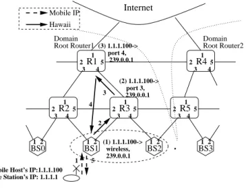
user does not move out of a domain while powered up. R3 Hawaii Mobile IP BS0 BS1 BS2 BS3 Internet 2 5 2 4 5 2 5 2 3 4 5 2 3 5 1 2 1 2 1 2 1 2 3 4 4 R2 3 R1 3 R4 R5 1 2 3 4 5 4 1 1 1 1 1 Root Router1 Domain Root Router2 Domain port 4, 239.0.0.1 239.0.0.1 port 3, wireless, 239.0.0.1 (1) 1.1.1.100-> (2) 1.1.1.100-> (3) 1.1.1.100->
Base Station’s IP: 1.1.1.1 Mobile Host’s IP:1.1.1.100
Figure 3: Power-up
In our architecture, when operating in a domain, the mobile host maintains the assigned IP address regardless of its location. In order to maintain IP routing between the domain root router and the mobile host, HAWAII establishes special paths as the mobile host moves. The algorithm used in updating selected routers to establish or maintain connectivity with a mobile host is termed a path setup scheme. The path setup scheme for power-up is illustrated in Figure 3.
The figure shows two HAWAII domains with border routers, domain root router 1 and 2. Two base stations, BS1 and BS2, are assumed to be part of a multicast group, 239.0.0.1; this has relevance to paging which will be discussed later. The HAWAII forwarding entries are shown adjacent to the routers. These entries are prepended with a message number indicating what message was responsible for es-tablishing the entry (a message number of zero indicates a pre-existing entry). The entry consists of an IP address with an outgoing interface number for forwarding packets destined to that IP address and a multicast address corresponding to the group of base stations to which the user is currently attached.
The mobile host first sends a Mobile IP registration message (1) to its current base station. The base station, BS1, identifies that the mobile host is powering up in its home domain based on parameters in
the registration message. It then adds a forwarding entry for the mobile host and initiates a HAWAII power-up message (2) to router R3. Router R3 similarly adds a forwarding entry to forward packets for the mobile host towards base station BS1 and sends the message (3) to the domain root router, R1. Router R1 adds a forwarding entry towards Router R3 and sends an acknowledgement (4) back to the base station which then sends a Mobile IP registration reply (5) to the mobile host.
At this time, packets destined for the mobile host’s IP address, 1.1.1.100, arrive from the internet to domain root router, R1, based on the subnet portion of the IP address (1.1.1.0) and then get delivered to the mobile host through Routers R1, R3 and base station BS1 based on the host-based forwarding entries established by HAWAII. Note that there is no tunneling involved in this case and packets traverse the optimal route to the mobile host.
3.2.2 Micro-mobility
Now let us consider what happens when the mobile host is handed off from base station BS1 to BS2. The sequence of messages exchanged is illustrated in Figure 4. Note that the mobile host maintains its IP address (1.1.1.100) as this movement is within a HAWAII domain.
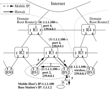
R3 Hawaii Mobile IP BS0 BS1 BS2 BS3 Internet 2 5 2 4 5 2 5 2 3 4 5 2 3 5 1 2 1 2 1 2 1 2 3 4 4 R2 3R1 3R4 R5 4 1 1 1 1 1 Root Router1 Domain Root Router2 Domain port 4, 239.0.0.1 239.0.0.1 239.0.0.1 2 3 4 5 1 port 2, 239.0.0.1 wireless, port 4, (2) 1.1.1.100-> (3) 1.1.1.100-> (0) 1.1.1.100-> (4) 1.1.1.100->
Base Station’s IP: 1.1.1.2 Mobile Host’s IP:1.1.1.100
As before, the mobile host sends a Mobile IP registration message (1) to its new base station, BS2, informing it that base station BS1 was its previous base station. The base station, BS2, initiates a HAWAII handoff message (2) towards base station, BS1. BS1 adds an entry for the mobile host so that future packets are ’forwarded’ towards the new base station, BS2. It then sends the HAWAII message (3) to Router R3. Router R3 changes its forwarding entry from port 3 to port 4 so that packets destined for the mobile host now travel to base station BS2. It then forwards the HAWAII message (4) to base station BS2, which updates its forwarding table and sends a Mobile IP registration reply to the mobile host.
Note that this particular way of updating the routers and base stations is called the forwarding path setup scheme in HAWAII. This is useful in networks such as TDMA, where the mobile host cannot listen to two base stations simultaneously. In the case of networks such as CDMA where the mobile host could listen to multiple base stations simultaneously, it is possible to directly divert traffic from router R3 instead of forwarding; this leads to a different algorithm for updating the routers and is called a non-forwarding path setup scheme in HAWAII. These schemes and other variations including mul-ticasting from router R3 during the handoff are discussed in detail in [7]. The advantage of custom tailoring these path setup schemes for different wireless networks is that disruption to user traffic can be minimized. This is especially critical in next generation wireless data networks where voice-over-IP and other multimedia traffic will likely be carried. Note that the path setup schemes can be the analogue of the soft-handoff functionality of current CDMA networks, albeit performed at the IP layer.
Another important aspect of HAWAII and its path setup schemes is that they operate locally. In Fig-ure 4, note that only router R3 and the two base stations are involved in processing the updates. Router R1 is unaffected by this movement of the mobile host as its forwarding entry pointing to Router R3 is unchanged. This leads to much better scalability than an approach based on Mobile IP. Performance results in [7] for typical network configuration show that HAWAII results in almost one tenth the
pro-cessing requirements of using a centralized approach based on Mobile IP.
Finally, maintaining the IP address of the mobile host unchanged across movements within the same domain results in straightforward support for Quality of Service (QoS). In the case of using a reservation protocol such as RSVP, reservations need only be restored locally during the handoff (at router R3 and base station BS2); prior reservations at other routers such as router R1 and the backbone routers can be maintained unchanged since the mobile host’s IP address, used to identify flows, remain the same.
3.2.3 Paging
Recall that in GPRS, the paging functionality is performed in a centralized fashion by a SGSN and can be considered as a link layer function. In our architecture, we use the HAWAII protocol to support IP-level paging in a distributed, scalable, and flexible manner.
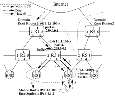
Assume that the mobile host illustrated in Figure 4 is idle and goes to standby state. Subsequently, the network only knows that the mobile host is present in one of the base stations in its paging area, denoted in this example by base stations BS1 and BS2. In our architecture, we use an administratively-scoped IP multicast group address (239.0.0.1) to identify the set of base stations belonging to the same paging area. Assume that at this time, IP packets destined for the mobile host arrive at the domain root router. The network then needs to page the base stations BS1 and BS2 to determine the exact location of the mobile host. The procedures involved in delivering the packet to the mobile host in this case is illustrated in Figure 5.
The data packets first arrive at router R1. Based on its forwarding entry, router R1 notes that the mobile host is in standby state. However, router R1 determines that it does not belong to the multicast tree of the paging area for the mobile host, 239.0.0.1 (we assume that the multicast tree connecting base stations BS1 and BS2 is rooted at router R3). Therefore, router R1 forwards the data packets downstream on port 4 towards router R3. Router R3 performs similar processing and identifies that it is part of the
R3 BS0 BS1 BS2 BS3 Internet 2 5 2 4 5 2 5 2 3 4 5 2 3 5 1 2 1 2 1 2 1 2 3 4 4 R2 3R1 3R4 R5 4 1 1 1 1 1 Root Router1 Domain Root Router2 Domain port 4, 239.0.0.1 239.0.0.1 239.0.0.1 wireless, port 4, Mobile IP Hawaii Data Buffer 1 2 2 3 4 1 (0) 1.1.1.100-> (3) 1.1.1.100-> (0,4) 1.1.1.100->
Mobile Host’s IP:1.1.1.100 Base Station’s IP: 1.1.1.2
Figure 5: Paging
multicast tree for the paging area of the mobile host. It then buffers the data packets and initiates a HAWAII page request (1) to the multicast group address. Base stations BS1 and BS2 which belong to the multicast group receive the page message and broadcast a page message (2) on their respective wireless interfaces utilizing the underlying link layer technology. The mobile host, which happens to remain under base station BS2 in this example, receives the link-layer page message (for example, by periodically scanning the broadcast paging channel) and sends a Mobile IP registration message (3) to the base station BS2. This triggers a HAWAII path setup message from base station BS2 to the paging initiator (4), router R3. Updated forwarding entries are also established at base station BS2 and router R3. The buffered data packets (as well as any arriving packets) are then forwarded to the mobile host through base station BS2.
A complete description of the paging procedure can be found in [9]. The motivation behind the algorithm is to push the burden of paging to the base station and low-level routers and away from the domain root router so that scalability is enhanced.
approach used in current cellular networks and presented in the example above allow only for a fixed set of base stations to belong to a paging area. In the IP-based approach, a paging area is determined by the composition of a multicast group. This enables other approaches such as hierarchical and per-user paging where different sets of base stations are paged for each user.
3.2.4 Macro-mobility
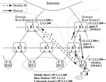
Finally, we illustrate the situation where the mobile host moves between base stations connected to different HAWAII domains. In this case, the mobile host acquires a second address, called the care-of address, in the new domain. In this section, we assume the co-located care-of address (CCOA) model of Mobile IP since the CCOA uniquely identifies the mobile host for QoS support. However, if necessary, a network-based care-of address model can also be incorporated. In this example, the mobile host acquires a CCOA of 2.2.2.200 from the new domain. The sequence of messages exchanged for the inter-domain handoff is illustrated in Figure 6.
R3 Hawaii Mobile IP BS0 BS1 BS2 BS3 Internet 2 5 2 4 5 2 5 2 3 4 5 2 3 5 1 2 1 2 1 2 1 2 3 4 4 R2 3 R1 3 R4 R5 4 1 1 1 1 1 Root Router1 Domain Root Router2 Domain 1 2.2.2.200 wireless, 239.0.0.2 3 2 5 6 7 4 239.0.0.2 port 4, 239.0.0.2 port 3, (1) 2.2.2.200-> (2) 2.2.2.200-> (3) 2.2.2.200-> (5) 1.1.1.100->
Mobile Host’s IP:1.1.1.100 Base Station’s IP: 1.1.1.2 Colocated Agent’s IP:2.2.2.200
Figure 6: Inter-domain handoff
The mobile host sends a Mobile IP registration message (1) to base station, BS3. Based on the parameters in the message, the base station detects that this is an inter-domain handoff. Base station BS3
first initiates the HAWAII power-up procedure in this domain (denoted by messages 2-4) for establishing host-based entries for the 2.2.2.200 co-located address. It then sends a Mobile IP registration message (5) to the home agent of the mobile host, router R1. In our architecture, the home agent is co-located with the domain root router. Thus, the home agent at router R1 establishes a tunnel entry, which will tunnel packets destined to the mobile host IP address of 1.1.1.100 to its new co-located address. Upon receiving a reply to the Mobile IP registration message (6) from the home agent, base station BS3 sends an acknowledgement to the mobile host (7).
At this time, packets destined to the 1.1.1.100 address of the mobile host reach router R1 and then get tunneled to the 2.2.2.200 address. The tunneled packets with the 2.2.2.200 address reach router R4 based on the subnet portion of the address and then gets forwarded through router R5 and base station BS3 to the mobile host based on the HAWAII forwarding entries established. Subsequent handoffs by the mobile host in this new domain will be handled locally by HAWAII as described previously in the micro-mobility section. Thus, the home agent is updated only when the mobile hosts crosses a domain boundary, a much rarer occurrence, resulting in reduced handoff latencies and improved scalability.
3.2.5 Security
HAWAII faces the same security concerns as any regionalized approach to IP mobility, such as [3]. Recall that HAWAII networks are organized hierarchically, and their performance advantage over basic Mobile IP is achieved through handoff procedures that involve only local nodes. Therefore, without involving the home agent, base stations must be able to (i) verify the authenticity of the Mobile IP message coming from the mobile host, and (ii) generate a reply that the mobile host will be able to verify as authentic. To achieve this goal, three separate security associations must be in place: the first between the base stations and the mobile host, the second between the base stations and the home agent, and the third between the home agent and the mobile host. For this purpose, an Authentication, Authorization
and Accounting (AAA) [1] infrastructure can be used to distribute three sets of authentication keys, to the mobile host, to the base stations, and to the home agent. The basic Mobile IP authentication scheme must also be modified. In particular, in case of handoffs that do not involve the home agent, mobile hosts must be prepared to receive registration replies that contain only authentication information generated by base stations. At the same time, home agents must be prepared to receive surrogate registration requests, generated by base stations on behalf of mobile nodes. Such requests will not contain any authentication information generated by the hosts, but only authentication data provided by the base stations.
4
Performance
We have implemented the HAWAII protocol on a testbed of PCs running the FreeBSD operating
sys-tem. The processing of a HAWAII handoff message at a given node takes only 0:156 milliseconds.
The handoff latency for a mobile host connected to a network through Lucent’s 2Mb/s WaveLAN is
approximately5milliseconds (including4milliseconds of latency on the wireless segment).
We next compare the performance of Mobile IP and HAWAII using simulation on a larger network with cross-traffic. We compare the disruption of HAWAII Forwarding and Non-Forwarding schemes with basic Mobile IP as well as the Mobile IP Route Optimization (RO) [6] proposal. In the simulation, the topology of the wireless access domain is a binary tree with three levels; at the lowest level, there are four base stations. The HA and the correspondent host are outside the domain while the mobile user is handed off between the four base stations in the experiment. We simulate audio traffic to the mobile host from a correspondent host (and through the HA in case of Mobile IP) in the form of 160 byte UDP packets transmitted every 20 ms (64 Kb/s).
In the case of an interactive audio application, a playout delay is typically used to overcome network jitter; if the packet arrives after its playout time, the packet is dropped. We are thus interested in the total packet loss which includes both packets dropped due to late arrival as well as packets lost in the network
0 1 2 3 4 5 6 40 60 80 100 120 140 160 180 200
Average number of dropped or lost packets per handoff
Playout delay (in ms) Non-Forwarding
Mobile IP RO Forwarding Mobile IP
(a) All schemes
0 2 4 6 8 10 12 14 0 100 200 300 400 500 600
Number of packet drops during handoff (in ms)
Playout delay (in ms) Delay=0ms Delay=5ms Delay=25ms Delay=50ms Delay=100ms (b) Impact of delay to HA
Figure 7: Packet loss during 2-hop handoff
due to handoff. In Figure 7(a), we plot the total of dropped and lost packets per handoff (averaged over 100 or more handoffs) versus playout delay for all the four schemes. In this simulation topology, the propagation delay from correspondent host to mobile host is 25ms for all the schemes except for the basic Mobile IP scheme which incurs an additional 100ms delay due to routing through the HA.
In the case of basic Mobile IP scheme, about 5 packets/handoff are lost in the network. This is because, in our configuration, the registration update from the mobile host takes about 100ms (link delay of 50ms and queueing delay of approximately 50 ms) to reach the HA. In this interval, about 5 packets are sent to the old base station and are lost. Let us now compare the remaining three schemes. Consider a playout delay value of 100ms in Figure 7(a). In this case, the Mobile IP RO scheme results in a total loss of about 3 packets/handoff while the HAWAII schemes result in the total loss of less than 1 packet/handoff. This is because the HAWAII schemes switch over very quickly to the new route, while in Mobile IP RO scheme, the HA and then the correspondent host must be notified before packets use the new route.
Among the HAWAII schemes, the Non-Forwarding scheme performs better than the Forwarding scheme since the Non-Forwarding scheme is able to utilize the mobile host’s ability to receive from multiple base stations.
We also examine the effect of the propagation delay to the HA on performance. The HAWAII schemes are unaffected since they operate locally. In the case of Mobile IP, as shown in Figure 7(b), when the delay to HA decreases, the performance approaches that of HAWAII. The same behavior is true for Mobile IP RO as well (not shown). Thus, by operating locally, the HAWAII schemes result in smaller disruption to interactive audio traffic compared to the Mobile IP schemes.
5
HAWAII-based Next Generation Wireless Data Network
Given the large installed base of wireless access networks, initial deployment of our architecture will have to interwork with current access networks. In this scenario, the base station controller of a GPRS-based access network or the Frame Selection entity of a CDMA-GPRS-based access network will likely be the mobile host’s next hop IP node. In this section we describe two ways in which HAWAII can be used in wide area wireless networks. In both cases, HAWAII is used to enhance micro-mobility with an IP-based network.
5.1
Pure HAWAII-based Network
Figure 8 shows a pure HAWAII network at a high level. The HAWAII protocol runs in the network connecting the mobile device and the domain router. In a GPRS network, the BSC/BTS act as a level 2 bridge to the air interface. In this case, mobility between BTS attached to the same BSC are handled by link layer techniques, and inter-BSC movement is handled by HAWAII. In a CDMA network, the frame selector would act as bridge to the air interface in the same manner as the BSC.
BTS/ BSC MD BTS/ BSC INTERNET NETWORK GPRS DR IP (HAWAII) CDMA IP Mobility VLR/ AAA AAA HLR/
VLR: Visitor Location Register HLR: Home Location Register BSC: Base Station Controller
BTS: Base Transceiver System MD: Mobile Device
DR: Domain Router AAA: Authentication, Authorization, and Accounting Server
Figure 8: HAWAII-based architecture
the access to the air interface, while an AAA based infrastructure should be used to support authentica-tion of Mobile IP and HAWAII transacauthentica-tions. Alternatively, the HLR could be augmented with an AAA interface, offering integrated support for GPRS/CDMA and Mobile IP/HAWAII authentication.
5.2
Partial HAWAII-based Network
BTS/ BSC
FA/HA: Foreign Agent/Home Agent
MD: Mobile Device
BTS: Base Transceiver System BSC: Base Station Control MD BTS/ BSC SGSN INTERNET DR/ GPRS BACKBONE NETWORK GPRS GGSN HAWAII GPRS/CDMA Mobility IP Mobility DR/ CDMA FA HA HAWAII IP NETWORK VLR/AAA HLR/AAA
HLR/VLR: Home/Visitor Location Register AAA: Authentication, Authorization, and Accounting Server
GGSN: Gateway GPRS Service Node SGSN: Serving GPRS Service Node DR : Domain Router
Figure 9 shows a scenario in which HAWAII is used for mobility management in the access net-work while remaining connected to a backbone netnet-work using different netnet-working technologies. The authentication infrastructure remains the same as in the pure HAWAII network example in the previous section.
For GSM, the backbone network would be a GPRS network. The HAWAII domain router is connected to the SGSN. GPRS protocols, such as GTP, would be used for registration, authentication, and high level mobility. HAWAII would be used for micro-mobility and paging support. In this scenario, the benefits of HAWAII’s micro-mobility management are realized for transporting user data, and the GPRS protocols are used to access databases allowing GPRS infrastructure and management to be re-used.
In a CDMA network, the backbone network would be basic Mobile IP. The foreign agent would be located at the domain root router. In this way, again micro-mobility would be handled by HAWAII and roaming by Mobile IP.
6
Conclusion
In this paper, we presented a homogeneous IP-based wireless access network architecture that supports different wide-area wireless technologies. This IP-based network used the internet standard, Mobile IP, for supporting macro-mobility of mobile hosts and HAWAII for supporting micro-mobility and paging functionality of current wireless networks. We also illustrated how the proposed IP-based solution can interwork with existing infrastructure so that incremental deployment can be achieved.
References
[1] P. Calhoun and C. E. Perkins “DIAMETER Mobile IP Extensions”, Internet Draft, Work in Progress, November 1998.
[2] Digital cellular telecommunication system, General Packet Radio Service, Service description -Stage 2, GSM 03.60 Version 6.0, ETSI, 1998.
[3] E. Gustafsson, A. Jonsson, C. Perkins, “Mobile IP Regional Tunnel Management,” Internet Draft, Work in Progress, August 1999.
[4] K. Nichols and S. Blake, “Differentiated Services Operational Model and Definitions,” Internet Draft, Feb 1998.
[5] C.E. Perkins, “IP Mobility Support,” Request for Comments 2002, Oct 1996.
[6] C.E. Perkins, and D.B. Johnson, “Route Optimization in Mobile IP,” Internet Draft, Nov. 1997. [7] R. Ramjee, T. La Porta, S. Thuel, K. Varadhan, and S.Y. Wang, “HAWAII: A Domain-based
ap-proach for Supporing Mobility in Wide-area Wireless Networks,” in Proceedings of International Conference on Network Protocols (ICNP), November 1999.
[8] R. Ramjee, T. La Porta, S. Thuel, K. Varadhan, and L. Salgarelli, “IP micro-mobility support using HAWAII,” Internet Draft, Work in Progress, June 1999.
[9] R. Ramjee, T. La Porta, and L. Li, “Paging support for IP mobility using HAWAII,” Internet Draft, Work in Progress, June 1999.
[10] S. Shenker, C. Partridge, and R. Guerin, “Specification of guaranteed quality of service,” Request for Comments 2212, September 1997.
[11] A. Valko, A. Campbell, and J. Gomez, “Cellular IP,” Internet Draft, November 1998.
Biographies
Ramachandran Ramjee received his B.Tech in Computer Science and Engineering from the Indian Institute of Technology, Madras, in 1992, and his M.S. and Ph.D. in Computer Science from University of Massachusetts, Amherst, in 1994 and 1997 respectively. He has been a Member of Technical Staff at
Bell Labs, Lucent Technologies since 1996. His research interests are signaling, mobility management, and quality of service issues in wireless and high speed networks.
Thomas F. La Porta received his B.S.E.E. and M.S.E.E. degrees from The Cooper Union, New York, NY, in 1986 and 1987 respectively, and his Ph.D. degree in Electrical Engineering from Columbia Uni-versity, New York, NY, in 1992. He joined AT&T Bell Laboratories in 1986. He is currently Head of the Networking Techniques Research Department in Bell Laboratories, Lucent Technologies where has has worked on various projects in wireless and mobile networking for the past several years. He received the Bell Labs Distinguished Technical Staff Award in 1996, and an Eta Kappa Nu Outstanding Young Electrical Engineer Award in 1996. His research interests include mobility management algorithms, signaling protocols and architectures for wireless and broadband networks, and protocol design. Dr. La Porta was the Editor-in-Chief of IEEE Personal Communications Magazine and is a technical editor on ACM/Baltzer Journal of Mobile Networking and Applications. He has has been an adjunct member of faculty at Columbia University where he has taught courses on mobile networking and protocol design. Luca Salgarelli received his Laurea (Dr.Eng. degree) in EE, at Polytechnic of Milan, and his Master degree (M.Phil.) in Computer Science at CEFRIEL (Research and Educational Centre for Information Technology), Milan, Italy. He is currently a Member of Technical Staff at Bell Labs, Lucent Technolo-gies. His interests are in designing, developing and evaluating protocols and software architectures for IP-based networks
Sandra Thuel received her B.S. in Computer Engineering from the University of Puerto Rico, Mayaguez, in 1986, and her M.S. and and Ph.D. in Electrical and Computer Engineering from Carnegie Mellon Uni-versity, Pittsburgh, in 1988 and 1993 respectively. She has been a Member of Technical Staff at Bell Labs, Lucent Technologies (formerly AT&T) since 1993. Her research interests are quality of service, scheduling and resource management, and issues regarding the convergence of voice and data networks.
Kannan Varadhan obtained his PhD from the University of Southern California in 1998. He is in-terested in robustness issues in protocol design; more recently, he has taken a fascination to studying routing protocol behaviour in the Internet, and its observable behaviour at the edges of the network and consequent effects on end-to-end protocols.
Li Li received his B.E. degree in Automation from Beijing Polytechnic University in 1993 and the M.E in Electrical Engineering from the Institute of Automation, Chinese Academy of Science in 1996. He is currently a doctoral candidate in the Computer Science Department at Cornell University. He is interested in mobile computing, computer networking and distributed systems. He is currently working in the area of mobile computing.