DXF Import and Export for EASE 4.0
Bruce C. Olson, Dr. Waldemar Richert – ADA Version 4.01 Copyright © 2002 Acoustic Design Ahnert
EASE 4.0 allows both the import and export of model information using the AutoCAD DXF file format. The module used for this capability is called EASE Import / Export.
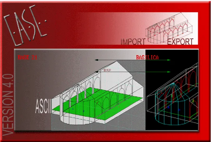
Figure 1: EASE 4.0 Import / Export Opening Screen The following topics are covered in this application note:
1) 'Import DXF' from the EASE Import / Export 'Tools' menu. (See Import of an AutoCAD DXF file into an Ease 4.0 Project file on page 2.)
2) 'Export DXF' from the EASE Import / Export 'Tools' menu. (See Export of an Ease 4.0 Project to an AutoCAD DXF file on page 7.)
3) 'Material Color Table' from the EASE Import / Export 'Tools' menu. (See Material and Color Translation on page 9.)
Import of an AutoCAD DXF file into an Ease 4.0 Project file
You can import a DXF file created with AutoCAD or other programs. Import DXF reads AutoCAD geometry data, which includes lines, 2D & 3D polylines, 2D solids, 3D faces, circles, and arcs. Import DXF cannot import regions or 3D solids. Use the AutoCAD FREEZE command or turn OFF
the layer of entities that you do not want to import into EASE. AutoCAD blocks can only be imported as EASE Loudspeakers, Listener Seats, Lamps, and IR Emitters. These blocks should be placed on suitable layers. (See Loudspeakers, Listener Seats, Lamps, and IR Emitters on page 6)
All EASE 4.0 elements can be represented in AutoCAD and then be imported via a DXF file. This includes Edges, Faces, Audience Areas, Loudspeakers, Listener Seats, Lamps, and IR Emitters.
Colors of elements and layers can be used to automatically assign an EASE Material to an imported Face. Placing entities on specially named layers for each wall material can also be used to assign the EASE Material. (See Material and Color Translation on page 9)
Note
Any AutoCAD entities that are not handled by the Import DXF command should be converted to a less complex representation in your CAD program. The AutoCAD EXPLODE command should
be used to simplify entities such as blocks, meshes, 3D objects, or other complex components. Blocks may need to be exploded multiple times if they have other blocks embedded in them. (Do not EXPLODE the blocks used for EASE Loudspeakers, Listener Seats, Lamps, and IR Emitters,
however.)
Some hints for AutoCAD Users
If a new drawing of a room is being created in AutoCAD, it is preferable to draw the room using AutoCAD 3D SOLIDs. The special shape of the room elements are then made with the commands UNION, SUBTRACT, INTERSECT, SLICE and INTERFERE.
You then can use the AutoCAD EXPORT command to create a 3D Studio file. Then you create a new
drawing and use the AutoCAD IMPORT command to create a file that uses the entities stored in the 3D
Studio file. Note
If this new drawing contains any mesh entities, you will need to use the AutoCAD explode command to simplify them.
If you want to import materials, please sort the faces to the right layers with the right layer names.
(See Material and Color Translation on page 9).
Now save the drawing in DXF format. This file will now only contain entities that can all be imported by EASE.
If you don’t want to do that procedure with 3D-Studio export, you will have to explode the BOXes and WEDGEs and 3D SOLIDs to LINEs. Do not use 3D SOLIDs with round faces (SPHERE, CYLINDER, CONE or TORUS), because those solids explode to BODYs, which cannot be imported into EASE with
Another very good (maybe the best) idea is to use the commands for 3D SURFACES in AutoCAD:
BOX, WEDGE, PYRAMID, CONE, SPHERE, DOME, DISH, TORUS, 3DMESH, REVSURF (revolved surface), TABSURF (tabulated surface), RULESURF (ruled surface) and EDGESURF (edge surface). These commands make nets of polylines with selectable MESH density. Now all curves are
approximated by plane areas. The command EXPLODE will the produce the 3DFACEs.
If you are not sure what kind of elements you have in your drawing and how many of them, use the AutoLISP command SSX. In the AutoCAD drawing, type SSX and then don’t pick an element, use the ENTER key. Next, type E for element and then the name of the element you are interested in, for
instance BODY, BLOCK and so on. After the final ENTER the number of those elements in the drawing
is output. If you pick one element from the display after typing SSX, the type of the element is explored. Alternatively you can use the “Property”-window, to analyse your drawing.
There are some additional programs, like ”3D Studio (MAX)” (*.3DS) or ”Corel Dream 3D” (*.D3D or *.RD4) which have a DXF export of 3D faces, which also produce no problems for DXF Import in EASE 4.0.
Some hints, if you do not have AutoCAD
In the case you are an EASE user and have received a DXF file from someplace, you may not know anything about the included elements, but nevertheless you want to import it into EASE. In this case try the following steps.
To get a fast impression of the contents of the DXF ‘black box’, use the DXF Import and do not choose any of the check-boxes in the dialog. Also, you should type zero for the ‘Vertex Snap Distance’ to maintain all the original coordinates. This will make the import routine faster.
After importing into EASE, have a look at the contents and make the first decisions.
Do you think that the DXF should contain more objects (maybe, because it is a big file)? Then try at first the option “Include ‘off’ and ‘frozen’ Layers”. Do you see more objects now?
Second, decide if the coordinates have the right numbers. If not, try to change the unit-conversion or the scale value in the DXF Import window. (U.S. Architectural units are, by default, inches in AutoCAD.)
Third, evaluate the need for EASE to do some automatic conversion of one EASE entity to another. • In the case where you see a lot of edges in your imported project which can build faces, choose the
‘Closed multiple Lines to Faces’ option.
• In the case where you see a lot of small faces in your imported project, choose the ‘Collect scattered Faces’ option.
• If this option creates faces which intersect, that means one face is going through another face, without an intersection line, then choose ‘Cut intersecting Faces’.
• If you get too many vertices on the borders of the faces, try to ‘Straighten border of Faces’ and increase the value of the ‘Vertex Snap Distance’ for a rougher grid.
• For making the project simpler, try to increase the ‘Plane Face Tolerance’ parameter. Then the ‘Collect scattered Faces’ option will combine more faces and the number of resulting faces will decrease.
• Last we will mention the ‘Waste outside Faces’ option. Use this option only if you are sure that the project has a lot of faces that do not belong to the inside of the room under test.
If you are unable to manipulate the DXF with AutoCAD, you will not be able to set appropriate spy-points (see below). The automatically set spy-point is in the geometrical center of all elements in the DXF file. So you cannot be sure that this point will be inside the room to analyse!
Next, for the first pass, do not choose a high ‘Detection Order’ or ‘Auto’ if the project has very many faces and you do not have much time! On the other hand, with this option you have the additional advantage that this routine will align all faces and will find two-fold faces.
Figure 2: Import DXF dialog box
Import DXF Details
The following EASE items will be created using the listed AutoCAD entities in the DXF file. ► Faces, and Edges:
For Edges, the EASE item color is from the AutoCAD Entity color. Faces will use the following to select the color and material to be used:
AutoCAD Layer Name starts with “EASE-$” • the AutoCAD Entity color is the default
- Face is one-fold
- EASE Face material is taken from the AutoCAD Layer Name (the part following the $ sign),
EASE Face color is the EASE default color, - EASE Rear material is the EASE default material, - EASE Rear color is the EASE default color. • the AutoCAD Entity color is any other color
- Face is two-fold.
- EASE Face material is taken from the AutoCAD Layer Name (the part following the $ sign),
EASE Face color is the EASE default color,
- EASE Rear material uses the AutoCAD Entity color to select the EASE material,
AutoCAD Layer Name starts with “EASE” - Face is two-fold.
- EASE Face material uses the AutoCAD Layer color to select the EASE material,
- EASE Face color is the AutoCAD Layer color,
- EASE Rear material uses the AutoCAD Entity color to select the EASE material,
- EASE Rear color is the AutoCAD Entity color.
Any other AutoCAD Layer Name
• the AutoCAD Layer color is the default, and
the AutoCAD Entity color is the default
- Face is one-fold
- EASE Face material is the EASE default material (ABSORBER), - EASE Face color is the EASE default color,
- EASE Rear material is the EASE default material (ABSORBER), - EASE Rear color is the EASE default color.
• the AutoCAD Layer color is the default, and
the AutoCAD Entity color is any color except the default
- Face is one-fold
- EASE Face material uses the AutoCAD Entity color to select the EASE material,
- EASE Face color is the AutoCAD Entity color,
- EASE Rear material is the EASE default material (ABSORBER), - EASE Rear color is the EASE default color.
• the AutoCAD Layer color is any color except the default, and
the AutoCAD Entity color is the default
- Face is one-fold.
- EASE Face material uses the AutoCAD Layer color to select the EASE material,
- EASE Face color is the AutoCAD Layer color,
- EASE Rear material is the EASE default material (ABSORBER), - EASE Rear color is the EASE default color.
• the AutoCAD Layer color is any color except the default, and
the AutoCAD Entity color is any color except the default
- Face is two-fold.
- EASE Face material uses the AutoCAD Layer color to select the EASE material,
- EASE Face color is the AutoCAD Layer color,
- EASE Rear material uses the AutoCAD Entity color to select the EASE material,
- EASE Rear color is the AutoCAD Entity color.
The EASE entities will be determined as follows: • 2D Lines [LINE]
- entered as an individual Edge,
- with thickness: entered as a quadrangle Face,
- connected lines that build a planar closed loop: entered as a single Face if the option Closed multiple Lines to Faces is checked in the Import DXF dialog window. • 2D and 3D Polylines[PLINE and 3DPOLY]
- treated like connected lines: entered as a single Face (whether closed or not in AutoCAD), - included arcs are converted to lines (see below: ARC),
- closed PLINE with thickness: several Faces create an enclosed body (with floor and ceiling),
- 3DPOLY that is planar: entered as a single Face, otherwise it is cut into multiple planar Faces. • 2D Solids [SOLID]
- entered as a quadrangle Face,
- with thickness: several Faces create an enclosed body (with floor and ceiling). • 3DFACE
- 3DFACE that is planar will be entered as a quadrangle Face,
• CIRCLE
Converted to a polygon using the number of edges determined by the values entered for Min. Circle Sectors and Max. Arc-Sectors Length in the Import DXF dialog window.
- entered as a single Face,
- with thickness: several Faces create an enclosed body (with floor and ceiling). • ARC
Converted to a polygon using the number of edges determined by the values entered for Min. Circle Sectors and Max. Arc-Sectors Length in the Import DXF dialog window.
- entered as multiple Edges. ► Audience Areas:
These entities will only be created as EASE Audience Area if they are located on the EASE-AREAS AutoCAD layer. They will be created as EASE Faces or Edges as above if not.
The EASE item color is from the AutoCAD Entity color.
• 2D Lines [LINE]
- 4 connected lines that build a planar closed loop: entered as a single Audience Area. • 2D and 3D Polylines[PLINE and 3DPOLY]
- treated like connected lines: entered as a single Audience Area, - included arcs are converted to lines.
• 3DFACE
- 3DFACE that is planar will be entered as a quadrangle Audience Area,
• CIRCLE
Converted to a 4-sided polygon using the first 4 edges determined by the values entered for Min. Circle Sectors and Max. Arc-Sectors Length in the Import DXF dialog window.
- entered as a single Audience Area.
► Loudspeakers, Listener Seats, Lamps, and IR Emitters: • BLOCK insert
To read BLOCK inserts as EASE elements, they must reside on a layer with a name that starts with EASE and then an arbitrary character (normally ‘-‘). The next two characters (shown in BOLD below) decide if and to what kind of EASE item the BLOCK will be converted.
- SPeakersor LOudspeakers ► Loudspeaker
- SEats ► Listener Seat
- LAmps or LIght ► Lamp
- IR (infrared) or EMitter or RAdiator or MOdulator ► IR Emitter
Ease reads the positions and the orientation (angles) of the BLOCK inserts and enters these
values into the property sheet for the EASE item. The entities that form the BLOCK and display the cases (shapes) are not used. The name of the block is used to select the correct entry from the appropriate EASE database.
The EASE item color is from the AutoCAD Entity color.
► Spy-Points:
A spy-point is a source of detection-rays for a special ray-tracing algorithm used to determine where the inside of the room is located. They are used when the Waste outside Faces checkbox is selected. If you have no spy-point in your DXF File, EASE will start with one in the center of the DXF coordinates for the room. For very complex projects it is strongly recommended that many spy-points be placed strategically in the AutoCAD drawing. Place at least one in every corridor or adjacent room connected by an open window. In this case you can choose a low Detection Order of 0 or 1 and the time for the ray-tracing will be acceptable.
• POINT
To read a POINT as an EASE Spy-Point, it must reside on a layer with a name that starts with
EASE-SPY.
Export of an Ease 4.0 Project to an AutoCAD DXF file
You can export an EASE 4.0 Project model to a DXF file that can be opened with AutoCAD. Export DXF writes EASE model data, which includes Edges, Faces, Areas, Loudspeakers, Seats, Lamps and Emitters. Export DXF cannot export Textures. AutoCAD blocks are created for EASE Loudspeakers, Seats, Lamps, and Emitters. These blocks will be placed on specially named layers. (See block (Block Insert) on page 8)
The EASE Material name will be used to create an AutoCAD layer for each set of faces that use the same wall material. The face color will also be assigned to assist with the later Import of the DXF file back into EASE. (See Material and Color Translation on page 9)
Figure 3: Export DXF dialog box
Export DXF Details
EASE will create separate AutoCAD layers for EASE items according to the following:
- EASE-$XYZ ► Face
Where XYZ is the EASE Wall Material label for the Front Face.
- EASE-AREAS ► Audience Area
- EASE-EDGES ► Edge
- EASE-SPEAKERS ► Loudspeaker
- EASE-SEATS ► Listener Seat
- EASE-LAMPS ► Lamp
- EASE-IR ► IR Emitter or Radiator or Modulator
The AutoCAD Color used for the Face (EASE-$XYZ) layers will be the color of the Front Face in EASE. All of the other layers will use the default AutoCAD color.
To visualize the room in AutoCAD you can use the command REGION. AutoCAD converts closed 2D
and exploded planar 3D polylines in the selection set to separate regions and then converts polylines and lines to form closed planar loops (outer boundaries and holes of a region). This will allow the use of the AutoCAD commands HIDE or RENDER to create shaded views.
Faces in EASE are allowed to be non-planar as long as the variation in the vertices of the face are less than the tolerance value set in EASE Options. There are three options for the export of the coordinates for EASE Faces. 3D Faces (Triangles) and Convert Faces to Exact Planes (2D Polylines) will allow AutoCAD to render all of the entities.
Note
2D Polylines will force the coordinates into a planar polyline, creating slightly different vertices that may show as gaps in the AutoCAD rendering.
The remaining option, 3D Polylines under Faces with EASE Coordinates will create entities that will not be rendered in AutoCAD if the coordinates are non-planar. This option will maintain the structure of the EASE Faces and the exact vertex coordinates, however.
The following AutoCAD entities will be created in the DXF file using the listed EASE items. ► 3DPOLY (3D Polylines):
• FACE
- placed on the EASE-$XYZ layer (Where XYZ is the EASE Wall Material for the Front Face),
- AutoCAD Layer color is from the EASE item color for the Front Face.
- one-fold face: AutoCAD Entity color is the default AutoCAD color (7).
- two-fold face: AutoCAD Entity color is from the EASE item color for the Rear Face.
• AUDIENCE AREA
- placed on the EASE-AREAS layer,
- AutoCAD Entity color is from the EASE item color.
► 3DFACE (Triangular 3D Faces):
• FACE
- placed on the EASE-$XYZ layer (Where XYZ is the EASE Wall Material for the Front Face),
- AutoCAD Layer color is from the EASE item color for the Front Face.
- one-fold face: AutoCAD Entity color is the default AutoCAD color (7).
- two-fold face: AutoCAD Entity color is from the EASE item color for the Rear Face.
► PLINE (2D Polylines):
• FACE
- placed on the EASE-$XYZ layer (Where XYZ is the EASE Wall Material for the Front Face), - AutoCAD Layer color is from the EASE item color for the Front Face.
- one-fold face: AutoCAD Entity color is the default AutoCAD color (7).
- two-fold face: AutoCAD Entity color is from the EASE item color for the Rear Face.
► LINE (3D Lines): • EDGE
- placed on the EASE-EDGES layer,
- AutoCAD Entity color is from the EASE item color.
► BLOCK (Block Insert):
• LOUDSPEAKER
- placed on the EASE-SPEAKERS layer,
- AutoCAD Entity color is from the EASE Loudspeaker Color.
• LISTENER SEAT
- placed on the EASE-SEATS layer,
- AutoCAD Entity color is from the EASE Listener Seat Color.
- AutoCAD BLOCK Name is always SEAT.
• LAMP
- placed on the EASE-LAMPS layer,
- AutoCAD Entity color is from the EASE Lamp Color.
- AutoCAD BLOCK Name is from the EASE Lamp Light Source.
• IR EMITTER
- placed on the EASE-IR layer,
- AutoCAD Entity color is from the EASE IR Emitter Color.
- AutoCAD BLOCK Name is from the EASE IR Emitter Radiator.
Material and Color Translation
This window is for the editing of the Material Color Coding for Import/Export DXF (see above). If a file called matcolor.lst exists in the EasePath folder, the dialog table will be filled with the values stored in it. If it does not exist, the set of default values will be placed in the table. Pressing OK will create this file from the values in the table if it does not yet exist.
If you want to import the correct materials from a DXF File you have to make Layers with the corresponding colors in AutoCad.
In Export DXF these Colors are created in the DXF file. If you have a material in your project which is not in your Material Color Table a layer will be created with a hint to the material-name and default color.