T
O O L
S
T I C K
B
A S E
A
D A P T E R
U
S E R
’
S
G
U I D E
1. Handling Recommendations
To enable development, the ToolStick Base Adapter and daughter cards are distributed without any protective plastics. To prevent damage to the devices and/or the host PC, please take into consideration the following recommendations when using the ToolStick:
Never connect or disconnect a daughter card to or from the ToolStick Base Adapter while the Base Adapter is
connected to a PC.
Always connect and disconnect the ToolStick Base Adapter from the PC by holding the large plastic connector.
Figure 1. Proper Method of Holding the ToolStick
Avoid directly touching any of the other components.
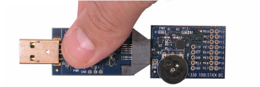
Figure 2. Improper Method of Holding the ToolStick
Manipulate mechanical devices on the daughter cards, such as potentiometers, with care to prevent the Base Adapter or daughter card from accidentally dislodging from their sockets.
2. Contents
The ToolStick Base Adapter package includes the following items:
ToolStick Base Adapter 3-foot USB extension cable
The ToolStick Starter Kit package includes the following items:
ToolStick Base Adapter
ToolStick C8051F330 Daughter Card 3-foot USB extension cable
A ToolStick Base Adapter is one component of the ToolStick development system and is not functional without a ToolStick daughter card. If the Base Adapter was not purchased as part of a Starter Kit, daughter cards can be purchased separately at www.silabs.com/toolstick.
3. ToolStick Overview
The purpose of the ToolStick is to provide a development and demonstration platform for Silicon Laboratories microcontrollers and to demonstrate the Silicon Laboratories software tools, including the Silicon Laboratories Integrated Development Environment (IDE).
The ToolStick development platform consists of two components: the ToolStick Base Adapter and a daughter card. The ToolStick Base Adapter provides a USB debug interface and data communications path between a Windows PC and a target microcontroller. The Base Adapter is powered from USB and also provides power to the daughter cards.
The target microcontroller and application circuitry are located on the daughter card. Some daughter cards, such as the C8051F330 daughter card, are used as general-purpose development platforms for the target microcontrollers and some are used to demonstrate a specific feature or application.
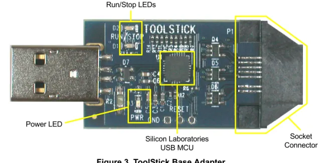
Figure 3 shows the ToolStick Base Adapter and identifies the various components.
Figure 3. ToolStick Base Adapter
Run/Stop LEDs
Silicon Laboratories USB MCU Power LED
Socket Connector
4. Getting Started
The necessary software to download, debug and communicate with the target microcontroller must be downloaded from www.silabs.com/toolstick. The following software is necessary to build a project, download code to, and communicate with the target microcontroller:
Silicon Laboratories Integrated Development Environment (IDE) Keil Demonstration Tools
ToolStick Terminal application
The Silicon Laboratories IDE and the Keil Demo Tools are described in more detail in Section 6. ToolStick Terminal provides data communication functions between the PC and the target microcontroller.
Other useful software that is provided on the ToolStick website includes:
Configuration Wizard 2
Keil uVision2 and uVision3 Drivers
Configuration Wizard 2 presents device peripheral options in a GUI and simplifies the generation of peripheral initialization code. The program is configurable to provide the output in C or assembly. The Keil uVision2 and uVision3 Drivers enable Keil uVision IDEs to debug Silicon Laboratories MCUs.
To simplify the download process, the necessary software described above is provided in two download packages. The ToolStick package includes the Keil Tools, example code, documentation including User’s Guides and data sheets, and the ToolStick Terminal application. The IDE, Configuration Wizard 2, and the Keil uVision Drivers are available as a separate download. After downloading and installing these two packages, see the following sections for information regarding the ToolStick functionality and how to use the Silicon Laboratories IDE.
5. ToolStick Base Adapter Functions
The ToolStick Base Adapter performs two main functions for the target microcontroller: 1) It provides a debug interface, and 2) it provides a data communication interface. The Base Adapter can perform only one of these functions at a time. The Base Adapter does not require any USB drivers to be installed for either of these functions because it uses standard USB class drivers.
The Base Adapter also provides power to the daughter cards. The yellow LED on the Base Adapter is a power indicator. If the yellow LED is on, the base adapter is properly connected to the PC and is receiving USB power. If the LED is off, the base adapter is not properly connected to the PC or the PC is in a suspended state.
5.1. Debug Mode
All of the Silicon Laboratories MCUs have on-chip debugging hardware that allows full, non-intrusive access to the CPU, peripherals and memory. The Base Adapter provides a USB interface between the Silicon Laboratories IDE and the on-chip debugging hardware.
The Base Adapter has green and red LEDs that indicate the status of the target microcontroller. If the red LED is on, the target microcontroller is halted. If the green LED is on, the target microcontroller is running. If neither LED is on, the Base Adapter is not connected in a debug session with the target microcontroller. If a debug session is not running and the target microcontroller is powered, it will start to execute its firmware.
5.2. Data Communication Mode
The connection between the Base Adapter and the daughter card includes four pins that are dedicated for data communication. Two of the pins are the UART pins, TX and RX. The other two pins can be configured as general purpose input-output (GPIO) pins or as UART hardware handshaking pins, RTS and CTS.
UART configuration/communication and GPIO configuration/access to the target microcontroller is performed using the Windows program, ToolStick Terminal. See the ToolStick Terminal help file for information on how to use
6. Silicon Laboratories IDE and Keil Demonstration Toolset
The Silicon Laboratories IDE integrates a source-code editor, source-level debugger, and an in-system Flash programmer. See the User's Guide for the ToolStick daughter card for detailed information on how to use the IDE. The Keil Demonstration Toolset includes a compiler, linker, and assembler and easily integrates into the IDE. The use of third-party compilers and assemblers is also supported.
6.1. IDE System Requirements
The Silicon Laboratories IDE requirements: Pentium-class host PC running Microsoft Windows 2000 or Windows XP. One available USB port.
64 MB RAM and 40 MB free HD space recommended.
6.2. Keil Assembler and Linker
The assembler and linker that are part of the Keil Demonstration Toolset are the same versions that are found in the full Keil Toolset. The complete assembler and linker reference manual can be found on-line under the Help
menu in the IDE or in the “SiLabs\MCU\hlp” directory (A51.pdf).
6.3. Keil Demonstration C51 C Compiler
The demonstration version of the C51 compiler is the same as the full version except code size is limited to 2 kB and the floating point library is not included. The C51 compiler reference manual can be found under the Help
menu in the IDE or in the “SiLabs\MCU\hlp” directory (C51.pdf).
6.4. 3rd Party Toolsets
The Silicon Laboratories IDE has native support for many other 8051 compilers. The full list of natively supported tools is:
Keil IAR
Raisonance Tasking Hi-Tech SDCC Dunfield
All of the example applications provided with the ToolStick package are written for the Keil toolset.
7. Information Locations
If the default installation directory is used for the ToolStick package, all ToolStick related documentation and code is installed in the “C:\SiLabs\MCU\ToolStick\” directory.
C
ONTACT
I
NFORMATION
Silicon Laboratories Inc. 400 West Cesar Chavez Austin, TX 78701 Tel: 1+(512) 416-8500 Fax: 1+(512) 416-9669 Toll Free: 1+(877) 444-3032 Email: [email protected] Internet: www.silabs.com
Silicon Laboratories and Silicon Labs are trademarks of Silicon Laboratories Inc.
Other products or brandnames mentioned herein are trademarks or registered trademarks of their respective holders.
The information in this document is believed to be accurate in all respects at the time of publication but is subject to change without notice. Silicon Laboratories assumes no responsibility for errors and omissions, and disclaims responsibility for any consequences resulting from the use of information included herein. Additionally, Silicon Laboratories assumes no responsibility for the functioning of undescribed features or parameters. Silicon Laboratories reserves the right to make changes without further notice. Silicon Laboratories makes no warranty, rep-resentation or guarantee regarding the suitability of its products for any particular purpose, nor does Silicon Laboratories assume any liability arising out of the application or use of any product or circuit, and specifically disclaims any and all liability, including without limitation conse-quential or incidental damages. Silicon Laboratories products are not designed, intended, or authorized for use in applications intended to support or sustain life, or for any other application in which the failure of the Silicon Laboratories product could create a situation where per-sonal injury or death may occur. Should Buyer purchase or use Silicon Laboratories products for any such unintended or unauthorized ap-plication, Buyer shall indemnify and hold Silicon Laboratories harmless against all claims and damages.