USER GUIDE
NI USB-6008/6009 OEM
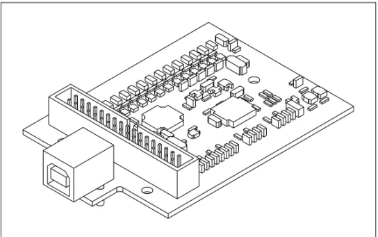
This document provides information about the dimensions, connectors, and other components of the National Instruments USB-6008/6009 OEM device. For more information about the device, refer to the USB-6008/6009 User Guide and Specifications document available at ni.com/manuals. Caution There are no product safety, electrogmagnetic compatibility (EMC), or CE marking compliance claims made for the NI USB-6008/6009 OEM devices. The NI USB-6008/6009 OEM device is intended to be used as a component of a larger system. National Instruments can help developers meet their compliance requirements. The end product supplier, however, is responsible for conforming to any and all compliance requirements.
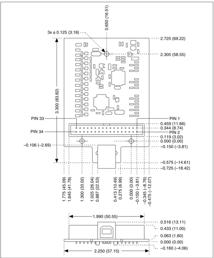
Dimensions
Figure 2 shows the USB-6008/6009 OEM device dimensions.
0.000 (0.00)
1.300 (33.02)
1.775 (45.09) –0.150 (–3.81)
–0.106 (–2.69) –0.150 (–3.81)
–0.575 (–14.61) –0.725 (–18.42) 0.119 (3.02) 0.000 (0.00) 0.344 (8.74)
0.516 (13.11) 2.305 (58.55) 2.725 (69.22)
0.650 (16.51)
0.413 (10.49)
0.887 (22.53)
1.025 (26.04) 0.275 (6.99)
0.459 (11.66)
1.645 (41.78) –0.345 (–8.76)
–0.475 (–12.07)
3.300 (83.82)
1.990 (50.55) PIN 33
PIN 34
PIN 1
PIN 2 3x φ 0.125 (3.18)
I/O Connector
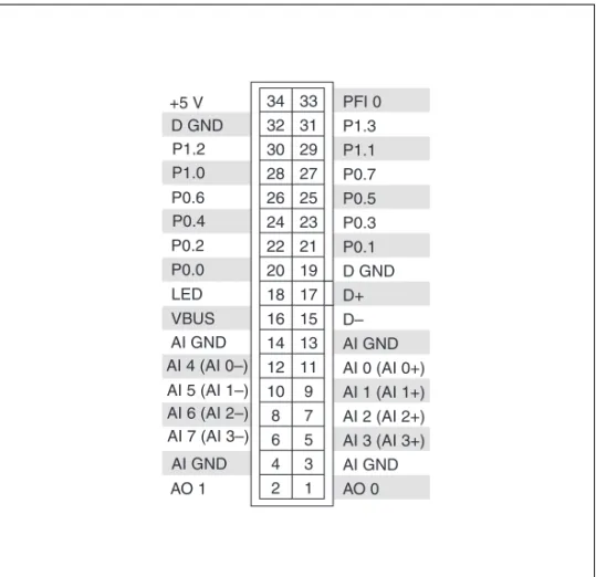
Figure 3 shows the USB-6008/6009 OEM device I/O connector pinout. AI signal names are shown in single-ended mode. Differential mode signal names are in parentheses.
Figure 3. USB-6008/6009 OEM Terminal Assignments
AO 1 AI GND AI 7 (AI 3–) AI 6 (AI 2–) AI 5 (AI 1–) AI 4 (AI 0–)
AI GND VBUS LED P0.0 P0.2 P0.4 P0.6 P1.0 P1.2 +5 V D GND AO 0 AI GND AI 3 (AI 3+) AI 2 (AI 2+) AI 1 (AI 1+) AI 0 (AI 0+) AI GND D– D+ D GND P0.1 P0.3 P0.5 P0.7 P1.1 P1.3 PFI 0
34 33 32 31
30 29 28 27 26 25 24 23
22 21 20 19 18 17 16 15 14 13
12 11 10 9 8 7 6 5 4 3 2 1 – –
Signal Descriptions
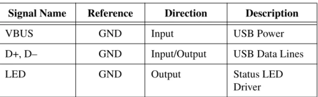
Most of the signals available on the I/O connector are described in the USB-6008/6009 User Guide and Specifications document available for download at ni.com/manuals. Table 1 describes additional signals on the I/O connector of the OEM devices.
Note The +2.5 V signal is not available on the USB-6008/6009 OEM device.
For more information about USB signals, refer to the Universal Serial Bus Specification accessible at www.usb.org.
Table 1. Signal Descriptions
Signal Name Reference Direction Description
VBUS GND Input USB Power
D+, D– GND Input/Output USB Data Lines
LED GND Output Status LED
Using the 34-Pin Connector with a Board Mount Socket
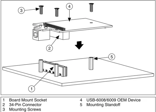
The USB-6008/6009 OEM device can be mounted to a motherboard using the 34-pin connector, as shown in Figure 4 and Figure 5.Figure 4. Mounting Using a 34-Pin Connector
Note Refer to the Device Components section for more information about mounting components.
Figure 5. USB Device Installed on Motherboard
1 Board Mount Socket 2 34-Pin Connector 3 Mounting Screws
4 USB-6008/6009 OEM Device 5 Mounting Standoff
4
2
1 3
Connecting to USB
You can use the USB connector on the USB-6008/6009 OEM device to connect to the USB host. In this case, leave the D+ and D– signals (on the 34-pin connector) and VBUS unconnected. If +5 V is needed, supply it from the 34-pin connector.
You can also use a USB connector on your motherboard to connect the USB-6008/6009 OEM device to the USB host through the 34-pin connector. In this case, do not connect to the USB connector on the USB-6008/6009 OEM device.
Using the Status LED Driver
The LED signal indicates the device status as described in Table 2. An open collector driver drives the LED signal. For applications that use the LED signal, connect a 4.7 kΩ resistor from the LED signal to the +5 V signal.
Two possible uses of the LED signal are as follows:
• To drive an LED to give a visual indication that the device is active. • To drive a watchdog timer circuit that monitors the device state.
Electrical Characteristics
Table 3 lists the LED electrical characteristics. Table 2. Device Status/LED Signal Behavior
Device Status LED Signal Behavior
USB device enumerated, configured and not suspended
Square wave with frequency of 2 Hz USB device is not enumerated, not configured,
or is suspended
Not driven (pulled up)
Table 3. Electrical Characteristics
Parameter Conditions Min Typ Max
Device Components
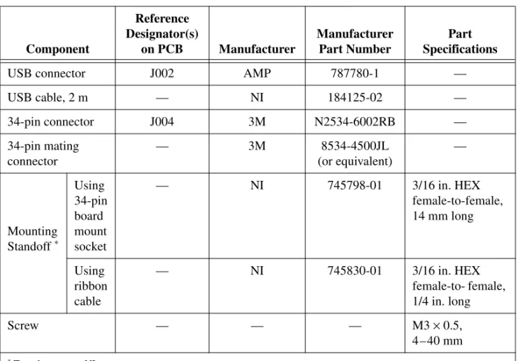
Table 4 lists the components used for interfacing and interacting with the USB-6008/6009 OEM device.
Table 4. NI USB-6008/6009 OEM Device Components
Component
Reference Designator(s)
on PCB Manufacturer
Manufacturer Part Number
Part Specifications
USB connector J002 AMP 787780-1 —
USB cable, 2 m — NI 184125-02 —
34-pin connector J004 3M N2534-6002RB —
34-pin mating connector
— 3M 8534-4500JL
(or equivalent)
—
Mounting Standoff *
Using 34-pin board mount socket
— NI 745798-01 3/16 in. HEX
female-to-female, 14 mm long
Using ribbon cable
— NI 745830-01 3/16 in. HEX
female-to- female, 1/4 in. long
Screw — — — M3 × 0.5,
4–40 mm
USB-6008/6009 OEM Device Specifications
Most specifications of the USB-6008/6009 OEM device are listed in the USB-6008/6009 User Guide and Specifications document on ni.com/manuals. The following sections contain exceptions to the main specifications:
External Voltage
Note 2.5 V output is not available.
Physical Characteristics
Dimensions ...8.76 cm × 5.72 cm × 1.55 cm (3.45 in. × 2.25 in. × 0.610 in.) I/O connector ...3M, 4-wall header
(part number: N2534-6002RB) Weight ...1 oz
National Instruments, NI, ni.com, and LabVIEW are trademarks of National Instruments Corporation. Refer to the Terms of Use section on ni.com/legal for more information about National Instruments trademarks. Other product and company names mentioned herein are trademarks or trade names of their respective companies. For patents covering National Instruments products, refer to the appropriate location: Help»Patents in your software, the patents.txt file on your CD, or
Where to Go for Support
The National Instruments Web site is your complete resource for technical support. At ni.com/support you have access to everything from troubleshooting and application development self-help resources to email and phone assistance from NI Application Engineers.
National Instruments corporate headquarters is located at 11500 North Mopac Expressway, Austin, Texas, 78759-3504. National Instruments also has offices located around the world to help address your support needs. For telephone support in the United States, create your service request at ni.com/support and follow the calling instructions or dial 512 795 8248. For telephone support outside the United States, contact your local branch office:
Australia 1800 300 800, Austria 43 0 662 45 79 90 0, Belgium 32 0 2 757 00 20, Brazil 55 11 3262 3599, Canada 800 433 3488, China 86 21 6555 7838,
Czech Republic 420 224 235 774, Denmark 45 45 76 26 00, Finland 385 0 9 725 725 11, France 33 0 1 48 14 24 24, Germany 49 0 89 741 31 30, India 91 80 41190000,
Israel 972 0 3 6393737, Italy 39 02 413091, Japan 81 3 5472 2970, Korea 82 02 3451 3400, Lebanon 961 0 1 33 28 28,
Malaysia 1800 887710, Mexico 01 800 010 0793,
Netherlands 31 0 348 433 466, New Zealand 0800 553 322, Norway 47 0 66 90 76 60, Poland 48 22 3390150,
Portugal 351 210 311 210, Russia 7 095 783 68 51, Singapore 1800 226 5886, Slovenia 386 3 425 4200, South Africa 27 0 11 805 8197, Spain 34 91 640 0085, Sweden 46 0 8 587 895 00, Switzerland 41 56 200 51 51, Taiwan 886 02 2377 2222, Thailand 662 278 6777, United Kingdom 44 0 1635 523545