1
HVAC Control & Balancing Dampers
Models VCD, MBD and RBD
• Selection • Construction • Performance
August
2013
H*
HVAC Control and
Balancing Dampers
®Commercial Control Dampers are used in buildings to regulate the flow of air in an HVAC system. They can be used in intake, exhaust, or mixed air applications. There are two categories of control dampers:
• Balancing
• Commercial Control
Balancing
Manual balancing dampers are control dampers that regulate the flow of air but are not intended to be used in applications as a positive shut-off or for automatic control. These dampers are shipped with manual hand quadrants that can be locked in place.
There are four balancing damper models available: • MBD-10/10M is a single blade
• MBD-15 is a multi-blade • MBDR-50 is a round blade
Remote balancing dampers offer the same function as a manual balancing damper plus the added benefit of controlling the damper remotely at a diffuser or wall plate. These remote balancing dampers are ideal for applications where it is difficult to gain access to manually adjust the dampers to balance airflow. The “EZ Balance” remote control operates the damper motor by connecting to the wall, ceiling, or diffuser mounted RJ11 connector.
There are two remote balancing damper models available: • RBD-10 (single blade)
• RBDR-50 (round blade)
MBD-15 • Multi-blade
• Meets SMACNA recommended construction requirements
MBDR-50 • Round blade * shown with optional
standoff bracket MBD-10 • Single blade RBDR-50 • Round blade • Factory-mounted actuator * Actuator shipped as a
kit for field installation
RBD-10 • Single blade
Manual and Remote
Balancing Dampers
®Quick Selection Chart
MBD-10 MBD-10M MBD-15 MBDR-50 RBD-10 RBDR-50 Blade Profile Single Blade X X X 3V X Round X X Material Galvanized X X X X X X Frame Gauge 20 (1) X X 18 (1.3) X X X 16 (1.5) X Bearings Synthetic X X X X Bronze O Axles Steel X X X
Linkage Material Steel X
Actuator
Manual Quadrant X X X X
1-1/2 in. Standoff Bracket O O X O
2 in. Standoff Bracket O O O O
Remote Powered 9 Volt Actuator X X Sizing Inches (mm) Minimum 6 x 4 (152 x 102) 8 x 4 (203 x 102) 6 x 6 (152 x 152) 4 (102) 6 x 4 (152 x 102) 4 (102) Maximum Single Section 36 x 12 (914 x 305) 36 x 12 (914 x 305) 48 x 60 (1219 x 1524) 24 (610) 36 x 12 (914 x 305) 24 (610) Maximum Multi-Section - -96 x -96 (2438 x 2438) - - -X = Standard O = Optional
Velocity
Pressure
0 1000 2000 3000 4000 5000 6000 MBD-10/10M MBD-15 MBDR-50 RBD-10 RBDR-50Feet per Minute (maximum)
0 1 2 3 4 5 MBD-10/10M MBD-15 MBDR-50 RBD-10 RBDR-50 Inches wg (maximum)
A wide variety of accessories are available for the RBD and RBDR series. They include: • Diffuser connector
• Wall plates with ports
• Round wall/ceiling plate with single port • Single gang outlet box
• EZ Balance handheld remote kit • Plenum and non-plenum rated cables • Cable connectors
EZ Balance handheld remote kit
Volume Control Dampers
VCD Series
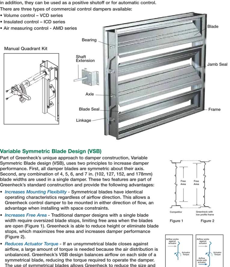
Axle Bearing Blade Frame Linkage Jamb Seal Blade Seal Shaft ExtensionManual Quadrant Kit
Commercial Control
Commercial control dampers regulate the flow of air in the same manner as manual balancing dampers, in addition, they can be used as a positive shutoff or for automatic control.
There are three types of commercial control dampers available: • Volume control – VCD series
• Insulated control – ICD series • Air measuring control - AMD series
Variable Symmetric Blade Design (VSB)
Part of Greenheck’s unique approach to damper construction, Variable Symmetric Blade design (VSB), uses two principles to increase damper performance. First, all damper blades are symmetric about their axis. Second, any combination of 4, 5, 6, and 7 in. (102, 127, 152, and 178mm) blade widths are used in a single damper. These two features are part of Greenheck’s standard construction and provide the following advantages: • Increases Mounting Flexibility - Symmetrical blades have identical
operating characteristics regardless of airflow direction. This allows a Greenheck control damper to be mounted in either direction of flow, an advantage when installing with space constraints.
• Increases Free Area - Traditional damper designs with a single blade width require oversized blade stops, limiting free area when the blades are open (Figure 1). Greenheck is able to reduce height or eliminate blade stops, which maximizes free area and increases damper performance (Figure 2).
• Reduces Actuator Torque - If an unsymmetrical blade closes against airflow, a large amount of torque is needed because the air distribution is unbalanced. Greenheck’s VSB design balances airflow on each side of a symmetrical blade, reducing the torque required to operate the damper. The use of symmetrical blades allows Greenheck to reduce the size and quantity of actuators used on dampers (Figure 3).
Actuator Torque Actuator Torque Airflow works against actuator Airflow works against actuator Airflow works with actuator Unbalanced Blade Requires Higher Torque
Balanced Blade Requires Less Torque
Free Area
Free Area
Competitor Greenheck with low profile frame
Figure 1 Figure 2
Figure 3
Design and Construction
Features
®Blades
3V blades are fabricated from a single thickness of 16 ga. (1.5mm) galvanized or stainless steel,
incorporating three longitudinal V-Type grooves running the full length of the blade to increase strength. This blade is standard on models VCD-15, 18, 20, 20V, 23, 23V, and SEVCD-23, designed for low to medium velocity and pressure applications.
Airfoil blades are constructed of double-skin galvanized steel, stainless steel, or heavy-gauge extruded aluminum. This blade design results in lower resistance to airflow and increased strength that is typically used in high pressure systems. Airfoil blades are standard on models VCD-33, 33V, 34, 40, 42, 42V, 43, 43V and SEVCD-33.
Parallel Blades
Opposed Blades
3V Blade Steel Airfoil Blade Aluminum Airfoil Blade
Frame
Greenheck control dampers utilize a 5 in. x 1 in. (127mm x 25mm) hat channel frame made of 16 ga. (1.5mm) steel, 16 ga. (1.5mm) stainless steel, or 0.125 in. (3mm) aluminum. Each frame is built with four separate pieces of material and joined by our Tog-L-Loc® process
resulting in the following advantages:
• Rigid frame - When two pieces of 16 ga. (1.5mm) steel are joined by the Tog-L-Loc®
system, the joint has an equivalent thickness of 10 ga. (3.5mm) steel.
• Increased corrosion resistance - High temperatures from welding remove the galvanized finish from damper frames. The Tog-L-Loc® process does not use heat, so Greenheck
damper frames have greater corrosion resistance by retaining the galvanized coating.
• Optimal free area - On dampers that are 17 in. (432mm) high or less, Greenheck uses a low profile top and bottom frame section to maximize free area.
• Square frame - Many damper manufacturers construct each frame from a single piece of sheet metal, formed into shape by bending at three corners and spot welding in one. This type of construction can produce weak corners that are not necessarily 90º, resulting in a frame that is out-of-square. Symptoms of out-of-square frames include blades that do not close properly and reduced leakage performance. Using four separate frame components (top, bottom, and two sides), Greenheck’s Tog-L-Loc® process
results in four sturdy, 90º joints. This ensures that each Greenheck damper is square and provides optimum performance in the field.
There are five frame options available: • Channel Frame (standard)
• Single Flange
• Single Reverse Flange • Double Flange
• Quick Connect (VCD-43, -43V; ICD Series)
Standard Frame Double Flange Quick Connect Single Flange (actuator side) Single Reverse Flange (opposite actuator) Tog-L-Loc® Reinforced Corner
Parallel Versus Opposed Blade Operation
Greenheck control dampers are offered with either parallel or opposed blades. Each style has distinguishing characteristics in regard to the type of operation required. • Parallel blade operation - This configuration requires the damper blades to rotate in
the same direction, parallel to one another. Parallel blade orientation is typically used when the damper operates in two positions, open or closed.
• Opposed blade operation - Adjacent damper blades rotate opposite one another under opposed blade configuration. Opposed blade configuration is typically used on dampers that modulate airflow.
Design and Construction
Features
Damper assemblies (larger than one section) are not designed to be structurally self-supporting. Additional horizontal bracing is recommended for support. Vertical bracing should be installed if required to hold against system pressure.
Multi-Section Dampers
Each of Greenheck’s VCD control dampers have a maximum size for a single damper section or panel. These sections vary from 48 in. wide x 60 in. high (1219mm x 1524mm) to 60 in. wide x 74 in. high (1524mm x 1880mm). Dampers larger than a single section will be made up of equal size sections which, depending upon model and size, may be shipped as a single complete assembly or as separate sections for field assembly. Multi-section damper assemblies are supplied with a coupler or factory installed jackshaft so all sections operate together.
Factory Installed Jackshaft Coupled (concealed between frames)
®
Linkage
Traditional damper linkages are found in the airstream, adding to the pressure drop of the damper blades and frame. Greenheck control dampers have blade linkages concealed in the frame to prevent additional pressure drop and unwanted noise. With standard plated steel construction (stainless steel optional), the linkage is engineered to accurately control each and every blade without need for adjustment.
Frame Options
The channel frame style allows a damper to be insert mounted into an opening without being concerned about the linkage sticking out past the frame. The single and single reverse flange frame can be insert mounted or directly mounted to the wall, mating surface or bulkhead. The quick connect frame design is extruded to match up to a TDC, TDF, or Ductmate connection to allow the damper to be cleated to the ductwork.
This illustration depicts how to mount a damper into a plenum wall.
No Top or Bottom
Greenheck’s standard control dampers are designed for installation in any position with the blades horizontal. The damper can be turned over so the actuator is on the left or right side. Optional vertical blade models can be turned with the actuator at the top or bottom.
Vertical Blade Standard
QR Codes
Greenheck has added QR (Quick Response) codes to the labels on commercial control and air measuring dampers.
When you scan the QR code with your smartphone, it will link to www.greenheck.com based on the model.
Options and
Accessories
Transitions
Greenheck control dampers can be supplied with the appropriate transition option in applications where dampers require installation in round or oval openings. Rectangular dampers are constructed zero, 1 inch (25mm), or 2 inches (51mm) larger than the transition dimensions and installed in a factory sleeve. The sleeve is transitioned at each end to the appropriate round,
oval, or rectangular size. Transition options available
Type O Type R Type C
A Damper Location L CL Damper Frame Sleeve Damper D* D* + 2 in. sq.
Factory Sleeve Option
Greenheck control dampers are available with factory furnished sleeves in lengths up to 48 in. (1219mm). Sleeves are constructed out of 10 through 20 ga. (3.25 through 0.91 mm) galvanized steel. When dampers are installed in factory sleeves, the “A” dimension specifies the location of damper within the sleeve.
Security Bars
When security becomes an issue, Greenheck offers optional factory-installed security bars. Security bars are factory welded into a 10 ga. (3.5mm) sleeve.
Paint Finishes
A wide variety of paint finishes are available including:
• Anodize • Industrial Epoxy
• Baked Enamel • Kynar®/Hylar®
• Epoxy • Permatector™
• Hi-Pro Polyester
See color charts on www.greenheck.com for standard color offering.
Open Close Indicator - OCI
The OCI contains two single pole, single throw switches used to indicate damper blade position. The switches provide positive open and closed signals when used in conjunction with remote indicator lights. Switches are physically linked to a damper blade and therefore give a true representation of the damper’s position.
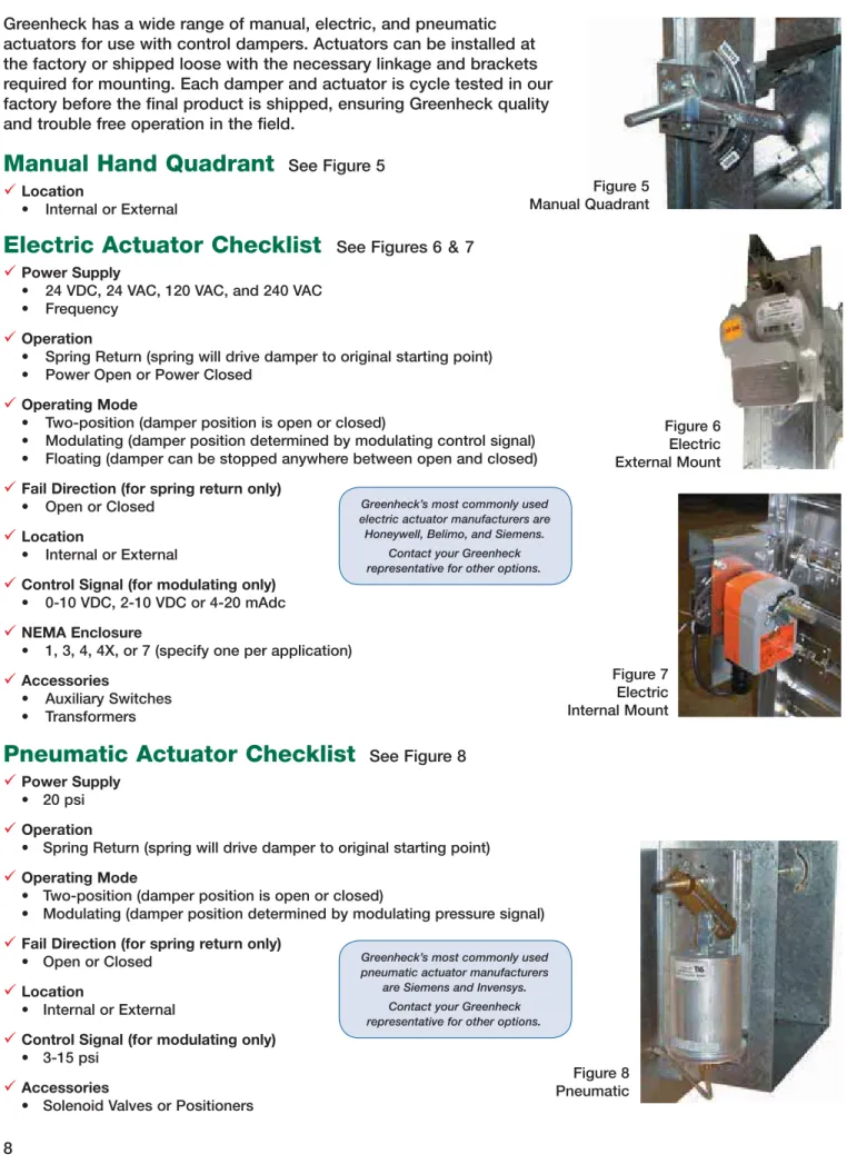
Figure 8 Pneumatic
Pneumatic Actuator Checklist
See Figure 8 9Power Supply
• 20 psi
9Operation
• Spring Return (spring will drive damper to original starting point)
9Operating Mode
• Two-position (damper position is open or closed)
• Modulating (damper position determined by modulating pressure signal)
9Fail Direction (for spring return only)
• Open or Closed
9Location
• Internal or External
9Control Signal (for modulating only)
• 3-15 psi
9Accessories
• Solenoid Valves or Positioners
Figure 5 Manual Quadrant
Manual Hand Quadrant
See Figure 5
9Location• Internal or External
Electric Actuator Checklist
See Figures 6
&7 9Power Supply• 24 VDC, 24 VAC, 120 VAC, and 240 VAC • Frequency
9Operation
• Spring Return (spring will drive damper to original starting point) • Power Open or Power Closed
9Operating Mode
• Two-position (damper position is open or closed)
• Modulating (damper position determined by modulating control signal) • Floating (damper can be stopped anywhere between open and closed)
9Fail Direction (for spring return only)
• Open or Closed
9Location
• Internal or External
9Control Signal (for modulating only)
• 0-10 VDC, 2-10 VDC or 4-20 mAdc
9NEMA Enclosure
• 1, 3, 4, 4X, or 7 (specify one per application)
9Accessories • Auxiliary Switches • Transformers Figure 6 Electric External Mount Figure 7 Electric Internal Mount
Greenheck’s most commonly used electric actuator manufacturers are Honeywell, Belimo, and Siemens.
Contact your Greenheck representative for other options.
Greenheck has a wide range of manual, electric, and pneumatic actuators for use with control dampers. Actuators can be installed at the factory or shipped loose with the necessary linkage and brackets required for mounting. Each damper and actuator is cycle tested in our factory before the final product is shipped, ensuring Greenheck quality and trouble free operation in the field.
Greenheck’s most commonly used pneumatic actuator manufacturers
are Siemens and Invensys. Contact your Greenheck representative for other options.
Wide Range
Damper Performance
Testing Criteria
® 5D 6D Figure 5.3 Figure 5.2 5D Figure 5.5 4 (W) (H) D = 3.14 D = Duct length W = Damper width H = Damper heightPressure drop testing was conducted in accordance with AMCA Standard 500-D using the three configurations shown. All data has been corrected to represent standard air at a density of .075 lb/ft3 (1.2 kg/m3).
Actual pressure drop found in an HVAC system is a combination of many factors. This pressure drop information, along with an analysis of other system influences should be used to estimate actual pressure losses for a damper installed in an HVAC system.
Figure 5.3 Illustrates a fully ducted damper. This configuration has the lowest pressure drop of the three test configurations because entrance and exit losses are minimized by straight duct runs upstream and downstream of the damper.
Figure 5.2 Illustrates a ducted damper exhausting air into an open area. This configuration has a lower pressure drop than Figure 5.5 because entrance losses are minimized by a straight duct run upstream of the damper.
Figure 5.5 Illustrates a plenum mounted damper. This configuration has the highest pressure drop because
of high entrance and exit losses due to the sudden changes of area in the system.
Greenheck Fan Corporation certifies that the model VCD-18, 23, 33, 34, 43, SEVCD-23 and 33 shown herein are licensed to bear the AMCA Seal. The ratings shown are based on tests and procedures performed in accordance with AMCA Publication 511 and comply with the requirements of the AMCA Certified Ratings Programs. The AMCA Certified Ratings Seal applies to Air Leakage and Air Performance ratings. Greenheck Fan Corporation certifies that the
model AMD-23 and 33, VCD-15, 20 and VCD-40 shown herein are licensed to bear the AMCA Seal. The ratings shown are based on tests and procedures performed in accordance with AMCA Publication 511 and comply with the requirements of the AMCA Certified Ratings Programs. The AMCA Certified Ratings Seal applies to Air Performance ratings only.
Greenheck Fan Corporation certifies that the model ICD-44 and ICD-45 shown herein is licensed to bear the AMCA Seal. The ratings shown are based on tests and procedures performed in accordance with AMCA Publication 511 and comply with the requirements of the AMCA Certified Ratings Programs. The AMCA Certified Ratings Seal applies to Air Leakage, Air Performance and Energy Efficiency ratings.
Pressure Drop Data
Dimension
inches 12x12 24x24 36x36 12x48 48x12
AMCA figure 5.2 5.3 5.5 5.2 5.3 5.5 5.2 5.3 5.5 5.2 5.3 5.5 5.2 5.3 5.5 Velocity
(ft/min) Pressure Drop in. wg
500 .01 .01 .03 .01 .01 .03 .01 .01 .02 .01 .01 .03 .01 .01 .03 1000 .05 .03 .13 .03 .02 .12 .02 .02 .10 .04 .03 .12 .03 .03 .12 1500 .11 .08 .30 .06 .04 .26 .05 .03 .22 .08 .07 .27 .07 .06 .28 2000 .19 .13 .53 .10 .07 .47 .09 .06 .40 .15 .12 .47 .12 .10 .49 2500 .29 .20 .82 .16 .11 .75 .14 .09 .62 .22 .18 .75 .18 .16 .77 3000 .41 .29 1.19 .23 .16 1.04 .19 .13 .90 .32 .26 1.07 .26 .22 1.12 3500 .55 .40 1.62 .30 .21 1.41 .27 .19 1.23 .43 .36 1.45 .36 .30 1.53 4000 .72 .51 2.10 .40 .28 1.90 .35 .25 1.62 .56 .46 1.91 .47 .39 2.01 VCD-15, 18, 20, 23 • Galvanized 3V blade • Economic VCD-15 and VCD-18 • Blade and jamb seals VCD-18 and 23
SEVCD-23
• 316 stainless steel 3V blade • 316 stainless steel construction • Blade and jamb seals
®
Dimension
inches 12x12 24x24 36x36 12x48 48x12
AMCA figure 5.2 5.3 5.5 5.2 5.3 5.5 5.2 5.3 5.5 5.2 5.3 5.5 5.2 5.3 5.5 Velocity
(ft/min) Pressure Drop in. wg
500 .01 .01 .03 .01 .01 .03 .01 .01 .02 .01 .01 .03 .01 .01 .03 1000 .05 .03 .13 .03 .02 .12 .02 .02 .10 .03 .03 .12 .04 .03 .12 1500 .11 .08 .30 .06 .04 .26 .05 .03 .22 .07 .06 .28 .08 .07 .27 2000 .19 .13 .53 .10 .07 .47 .09 .06 .40 .12 .10 .49 .15 .12 .47 2500 .29 .20 .82 .16 .11 .75 .14 .09 .62 .18 .16 .77 .22 .18 .75 3000 .41 .29 1.19 .23 .16 1.04 .19 .13 .90 .26 .22 1.12 .32 .26 1.07 3500 .55 .40 1.62 .30 .21 1.41 .27 .19 1.23 .36 .30 1.53 .43 .36 1.45 4000 .72 .51 2.10 .40 .28 1.90 .35 .25 1.62 .47 .39 2.01 .56 .46 1.91 VCD-20V and 23V • Vertical 3V blade
• Blade and jamb seals VCD-23V
Dimension
inches 12x12 24x24 36x36 12x48 48x12
AMCA figure 5.2 5.3 5.5 5.2 5.3 5.5 5.2 5.3 5.5 5.2 5.3 5.5 .5.2 5.3 5.5 Velocity
(ft/min) Pressure Drop in. wg
500 .01 .01 .03 .01 .01 .03 .01 .01 .02 .01 .01 .03 .01 .01 .03 1000 .03 .02 .12 .03 .01 .11 .02 .01 .09 .03 .02 .11 .02 .02 .11 1500 .07 .05 .27 .06 .03 .26 .04 .02 .21 .07 .04 .24 .04 .04 .24 2000 .13 .08 .48 .10 .05 .45 .07 .04 .38 .11 .08 .43 .08 .07 .44 2500 .19 .12 .74 .15 .09 .71 .11 .06 .58 .17 .12 .67 .12 .11 .68 3000 .26 .17 1.07 .21 .13 1.02 .15 .08 .85 .23 .17 .96 .16 .15 .97 3500 .35 .23 1.46 .28 .17 1.40 .20 .12 1.15 .31 .22 1.31 .21 .20 1.32 4000 .45 .30 1.91 .36 .22 1.89 .26 .15 1.52 .39 .29 1.71 .27 .25 1.73 VCD-33 and 34
• Galvanized airfoil blade • Insulated airfoil VCD-34 • Blade and jamb seals
SEVCD-33
• 316 stainless steel airfoil blade • 316 stainless steel construction • Blade and jamb seals
Pressure Drop Data
®Dimension
inches 12x12 24x24 36x36 12x48 48x12
AMCA figure 5.2 5.3 5.5 5.2 5.3 5.5 5.2 5.3 5.5 5.2 5.3 5.5 5.2 5.3 5.5 Velocity
(ft/min) Pressure Drop in. wg
500 .01 .01 .03 .01 .01 .03 .01 .01 .02 .01 .01 .03 .01 .01 .03 1000 .03 .02 .12 .03 .01 .11 .02 .01 .09 .02 .02 .11 .03 .02 .11 1500 .07 .05 .27 .06 .03 .26 .04 .02 .21 .04 .04 .24 .07 .04 .24 2000 .13 .08 .48 .10 .05 .45 .07 .04 .38 .08 .07 .44 .11 .08 .43 2500 .19 .12 .74 .15 .09 .71 .11 .06 .58 .12 .11 .68 .17 .12 .67 3000 .26 .17 1.07 .21 .13 1.02 .15 .08 .85 .16 .15 .97 .23 .17 .96 3500 .35 .23 1.46 .28 .17 1.40 .20 .12 1.15 .21 .20 1.32 .31 .22 1.31 4000 .45 .30 1.91 .36 .22 1.89 .26 .15 1.52 .27 .25 1.73 .39 .29 1.71 VCD-33V
• Vertical galvanized airfoil blade • Blade and jamb seals
Dimension
inches 12x12 24x24 36x36 12x48 48x12
AMCA figure 5.2 5.3 5.5 5.2 5.3 5.5 5.2 5.3 5.5 5.2 5.3 5.5 5.2 5.3 5.5 Velocity
(ft/min) Pressure Drop in. wg
500 .08 .05 .10 .01 .01 .03 .01 .01 .03 .01 .01 .03 .06 .03 .08 1000 .31 .20 .40 .05 .02 .12 .04 .02 .11 .05 .03 .12 .23 .13 .29 1500 .69 .45 .88 .11 .05 .29 .09 .04 .26 .11 .07 .27 .52 .29 .63 2000 1.19 .76 1.54 .19 .10 .52 .16 .07 .46 .20 .12 .49 .91 .51 1.12 2500 1.84 1.19 2.41 .30 .15 .80 .24 .10 .72 .30 .19 .76 1.43 .81 1.76 3000 2.67 1.7 3.45 .43 .22 1.14 .35 .15 1.04 .43 .26 1.11 2.05 1.16 2.52 3500 3.59 2.29 4.75 .58 .3 1.6 .48 .20 1.43 .59 .36 1.53 2.82 1.59 3.40 4000 4.64 2.97 6.09 .76 .40 2.14 .62 .27 1.87 .77 .46 2.00 3.69 2.09 4.52 VCD-40
• Extruded aluminum airfoil blade • Blades contained within the frame • Blade and jamb seals
Dimension
inches 12x12 24x24 36x36 12x48 48x12
AMCA figure 5.2 5.3 5.5 5.2 5.3 5.5 5.2 5.3 5.5 5.2 5.3 5.5 5.2 5.3 5.5 Velocity
(ft/min) Pressure Drop in. wg
500 .05 .03 .07 .01 .01 .04 .01 .01 .02 .01 .01 .03 .03 .02 .05 1000 .18 .12 .28 .05 .03 .17 .04 .02 .12 .01 .04 .18 .11 .06 .19 1500 .43 .28 .62 .12 .06 .37 .09 .05 .28 .14 .09 .40 .25 .14 .44 2000 .76 .49 1.11 .22 .11 .66 .17 .08 .50 .25 .16 .72 .44 .25 .78 2500 1.19 .77 1.73 .34 .17 1.04 .26 .13 .78 .39 .25 1.12 .69 .39 1.21 3000 1.71 1.11 2.50 .49 .24 1.50 .38 .19 1.13 .57 .36 1.62 1.0 .57 1.75 3500 2.33 1.51 3.41 .66 .33 2.04 .51 .26 1.53 .77 .49 2.21 1.36 .77 2.38 4000 3.04 1.98 4.45 .87 .43 2.66 .67 .34 2.01 1.01 .64 2.88 1.78 1.01 3.11 VCD-42
• Extruded aluminum airfoil blade • Galvanized frame
Pressure Drop Data
Dimension
inches 12x12 24x24 36x36 12x48 48x12
AMCA figure 5.2 5.3 5.5 5.2 5.3 5.5 5.2 5.3 5.5 5.2 5.3 5.5 5.2 5.3 5.5 Velocity
(ft/min) Pressure Drop in. wg
500 .01 .01 .04 .01 .01 .03 .01 .01 .03 .01 .01 .03 .01 .01 .03 1000 .06 .03 .14 .04 .02 .12 .03 .01 .10 .04 .03 .11 .03 .02 .11 1500 .13 .07 .31 .10 .04 .27 .06 .02 .22 .10 .06 .25 .06 .04 .26 2000 .23 .14 .55 .18 .08 .48 .12 .04 .39 .17 .11 .46 .10 .08 .46 2500 .35 .21 .86 .28 .13 .75 .18 .06 .61 .26 .17 .72 .16 .12 .72 3000 .50 .29 1.23 .40 .19 1.07 .26 .09 .87 .38 .25 1.05 .23 .18 1.02 3500 .68 .39 1.67 .54 .26 1.47 .35 .13 1.19 .52 .34 1.43 .30 .24 1.40 4000 .88 .51 2.19 .70 .34 1.91 .46 .17 1.56 .68 .45 1.87 .39 .31 1.83 VCD-43
• Extruded aluminum airfoil blade • Aluminum frame
• Blade and jamb seals
®
Dimension
inches 12x12 24x24 36x36 12x48 48x12
AMCA figure 5.2 5.3 5.5 5.2 5.3 5.5 5.2 5.3 5.5 5.2 5.3 5.5 5.2 5.3 5.5 Velocity
(ft/min) Pressure Drop in. wg
500 .05 .03 .07 .01 .01 .04 .01 .01 .02 .03 .02 .05 .01 .01 .03 1000 .18 .12 .28 .05 .03 .17 .04 .02 .12 .11 .06 .19 .01 .04 .18 1500 .43 .28 .62 .12 .06 .37 .09 .05 .28 .25 .14 .44 .14 .09 .40 2000 .76 .49 1.11 .22 .11 .66 .17 .08 .50 .44 .25 .78 .25 .16 .72 2500 1.19 .77 1.73 .34 .17 1.04 .26 .13 .78 .69 .39 1.21 .39 .25 1.12 3000 1.71 1.11 2.50 .49 .24 1.50 .38 .19 1.13 1.0 .57 1.75 .57 .36 1.62 3500 2.33 1.51 3.41 .66 .33 2.04 .51 .26 1.53 1.36 .77 2.38 .77 .49 2.21 4000 3.04 1.98 4.45 .87 .43 2.66 .67 .34 2.01 1.78 1.01 3.11 1.04 .64 2.88 VCD-42V
• Vertical extruded aluminum airfoil blade • Galvanized frame
• Blade and jamb seals
VCD-43V
• Vertical extruded aluminum airfoil blade • Aluminum frame
• Blade and jamb seals Dimension
inches 12x12 24x24 36x36 12x48 48x12
AMCA figure 5.2 5.3 5.5 5.2 5.3 5.5 5.2 5.3 5.5 5.2 5.3 5.5 5.2 5.3 5.5 Velocity
(ft/min) Pressure Drop in. wg
500 .01 .01 .04 .01 .01 .03 .01 .01 .03 .01 .01 .03 .01 .01 .03 1000 .06 .03 .14 .04 .02 .12 .03 .01 .10 .03 .02 .11 .04 .03 .11 1500 .13 .07 .31 .10 .04 .27 .06 .02 .22 .06 .04 .26 .10 .06 .25 2000 .23 .14 .55 .18 .08 .48 .12 .04 .39 .10 .08 .46 .17 .11 .46 2500 .35 .21 .86 .28 .13 .75 .18 .06 .61 .16 .12 .72 .26 .17 .72 3000 .50 .29 1.23 .40 .19 1.07 .26 .09 .87 .23 .18 1.02 .38 .25 1.05 3500 .68 .39 1.67 .54 .26 1.47 .35 .13 1.19 .30 .24 1.40 .52 .34 1.43 4000 .88 .51 2.19 .70 .34 1.91 .46 .17 1.56 .39 .31 1.83 .68 .45 1.87
Pressure Drop Data
®Dimension
inches 12 24
AMCA figure 5.2 5.3 5.5 5.2 5.3 5.5 Velocity
(ft/min) Pressure Drop in. wg
500 .01 .01 .02 .01 .01 .02 1000 .06 .02 .10 .04 .01 .09 1500 .13 .05 .22 .08 .03 .20 2000 .23 .08 .38 .15 .06 .36 2500 .37 .13 .60 .23 .09 .56 3000 .53 .19 .86 .33 .13 .81 Dimension inches 12 24 36 AMCA figure 5.2 5.3 5.5 5.2 5.3 5.5 5.2 5.3 5.5 Velocity
(ft/min) Pressure Drop in. wg
500 .04 .03 .05 .03 .02 .04 .05 .05 .06 1000 .15 .11 .19 .13 .10 .15 .19 .20 .25 1500 .33 .25 .42 .29 .21 .33 .42 .44 .57 2000 .59 .45 .75 .51 .38 .59 .75 .79 1.01 2500 .93 .70 1.18 .79 .60 .92 1.18 1.23 1.58 VCDR-50 and 53
• Insert type round single blade • Blade seals VCDR-53
VCDRM-50 and 53
• Insert type round multi-blade • Blade seals VCDRM-53
Pressure Drop Comparison
Greenheck compared the AMCA licensed pressure drop data of a VCD-33 12 in. wide x 12 in. high (305mm x 305mm) versus a competitor’s equivalent 12 in. wide x 12 in. high (305mm x 305mm) damper. Both dampers were installed in an identical system which drew 2000 ft./min. of airflow through them. The results were dramatic!
0.01 0.1 1.0 10.0 P res s ure D rop (i n. wg) Velocity (ft./min)
AMCA Licensed Pressure Drop Data
AMCA Figure 5.3 12 in. x 12 in. Fabricated Airfoil Damper
Competitor
Greenheck VCD-33
0.08 in. wg 0.34 in. wg
Air Leakage
Performance
®Air Leakage Data
VCD-33, 34
SEVCD-33 Leakage Class*
Maximum Damper Width 1 in. wg (0.25 kPa) 4 in. wg (1 kPa) 8 in. wg (2 kPa) 10 in. wg (2.5 kPa) 60 in. (1524mm) 1A 1 1 1 Torque
Data is based on a torque of 7.0 in-lb/ft² (0.79 N·m) applied to close and seat the damper during the test. Air leakage is based on operation between 32° and 120°F (0 and 49°C).
Tested for leakage in accordance with ANSI/AMCA Standard 500-D, Figure 5.5.
Tested for air performance in accordance with ANSI/AMCA Standard 500-D, Figures 5.2, 5.3 and 5.5.
Torque
Data is based on a torque of 5.0 in-lb/ft² (0.56 N·m) applied to close and seat the damper during the test.
VCD-18 Leakage Class* Maximum Damper Width 1 in. wg (0.25 kPa) 2 in. wg (0.5 kPa) 48 in. (1219mm) 1A 1
VCD-23, SEVCD-23 Leakage Class*
Maximum Damper Width 1 in. wg (0.25 kPa) 4 in. wg (1 kPa) 5 in. wg (1.2 kPa) 48 in. (1219mm) 1A 1 1 VCD-43 Leakage Class* Maximum Damper Width 1 in. wg (0.25 kPa) 4 in. wg (1 kPa) 8 in. wg (2 kPa) 10 in. wg (2.5 kPa) 60 in. (1524mm) 1A 1 1 1
Three common code energy standards that pertain to dampers are:
• ASHRAE Standard 90.1 - Energy Standard for Buildings except Low-Rise Residential Buildings • California Title 24
• IECC - International Energy Conservation Code
Here are the primary requirements for dampers based on each standard:
ASHRAE Standard 90.1 (2010 edition) states that maximum damper leakage at 1 in. wg for a :
• non-motorized damper is 20 cfm/ft2 or
• motorized damper is 4 cfm/ft2. ( See Table 6.4.3.4.3 from ASHRAE Standard 90.1)
California Title 24 (2013 edition, section 140.4.4) states that the dampers shall be certified in accordance
with AMCA Publication 511 to have a maximum leakage of 10 cfm/ft2 at 1 in. wg. The dampers have been
tested and are able to open and close against the rated airflow and pressure of the system after 60,000 damper opening and closing cycles.
IECC (2012, section C402.4.5.2) that outdoor air supply and exhaust opening be supplied with Class 1A
motorized dampers with a maximum leakage rate of 4 cfm/ft2 at 1 in. wg when tested in accordance with
AMCA 500D.
Specialty Control
Dampers
Damper/Louver in a Common Sleeve
Greenheck can provide a damper and louver in a common sleeve for applications requiring single unit assembly. This assembly makes it convenient for installing in the field as one unit instead of dealing with multiple units (consult factory for more information).
HEIGHT DAMPER 21.000 SLEEVE LENGTH 1.250 DAMPER LOCATION LOUVER SLEEV
Face & Bypass Dampers
The face and bypass dampers are used in applications where two dampers are connected together allowing one damper to open while the other damper closes. The FBH-43 is horizontal style (side-by-side). The FBV-43 is vertical style (stacked).
*Leakage Class Definitions
The maximum allowable leakage is defined by AMCA as the following:
• Leakage Class 1A - 3 cfm/ft2 @ 1 in. wg (Class 1A is only defined at 1 in. wg).
• Leakage Class 1 - 4 cfm/ft2 @ 1 in. wg
- 8 cfm/ft2 @ 4 in. wg - 11 cfm/ft2 @ 8 in. wg - 12.6 cfm/ft2 @ 10 in. wg Maximum Leakage cfm/sq. ft. (cmh/sq.m) Model Pressure @ 1 in. wg (.25 kPa) @ 4 in. wg (1 kPa) VCD-23V, 43V Class 1A Class 1 VCD-40 Class 1A Class 1 VCD-33, 42, 42V Class 1A Class 1 VCDR-53 Class 1 Class 1 VCDRM-53 Class 1 Class 1 21.000 SLEEVE LENGTH FBH FBV ®
Specialty Control Dampers
Greenheck Fan Corporation certifies that the model VCD-18, 23, 33, 34, 43, SEVCD-23 and 33 shown herein are licensed to bear the AMCA Seal. The ratings shown are based on tests and procedures performed in accordance with AMCA Publication 511 and comply with the requirements of the AMCA Certified Ratings Programs. The AMCA Certified Ratings Seal applies to Air Leakage and Air Performance ratings.
Greenheck Fan Corporation certifies that the model ICD-44 and ICD-45 shown herein is licensed to bear the AMCA Seal. The ratings shown are based on tests and procedures performed in accordance with AMCA Publication 511 and comply with the requirements of the AMCA Certified Ratings Programs. The AMCA Certified Ratings Seal applies to Air Leakage, Air Performance and Energy Efficiency ratings.
Specialty Control
Dampers
Air Measuring Products
Airflow measuring products are used to accurately measure and control air. Applications include meeting the minimum outdoor air requirements of ASHRAE Standard 62 or California Title 24 by providing accurate monitoring and control of outside air.
Why is outside air measurement important?
There are many significant benefits to monitoring outside air volumes. First, by measuring the amount of outside air coming into a building, you can be assured the building is in compliance with all applicable indoor air quality codes including ASHRAE Standard 62 and California Title 24. Meeting these minimum requirements reduces indoor airborne viruses and bacteria which can lead to Sick Building Syndrome. Studies have shown that inhabitants in buildings that are under ventilated suffer from reduced productivity levels.
AMS
®
ICD - Insulated Control Damper
Greenheck’s ICD dampers were developed for applications where it is necessary to minimize the thermal transfer and reduce condensation. ICD series dampers meet Class 1A leakage of less than 3 cfm/sq. ft. @ 1 in. wg (55 cmh/m2 @ .25 kPa). ICD series dampers can be used in
applications down to -70°F (-56°C) and up to 200°F (93°C) for: • Cold food storage warehouses
• Buildings/warehouse • Rooftop intake or exhaust
AMCA Certified Energy Efficiency Performance
A damper’s Thermal Efficiency Ratio (E) is a comparison of the thermal performance of the tested damper with a standard reference damper. A damper that is twice as efficient as the reference damper would have an E of 100%.
Cross section of thermally broken frame and blade
ICD-44 ICD-45
Maximum Velocity - ft/min. (m/s) 4000 (20.3) 4000 (20.3)
Maximum Pressure - in. wg (kPa) 8 (2) 8 (2)
Thermal Efficiency Ratio (E) 593% 941%
Temperature Range - °F (C°) -70 to 200 (-56 to 93) -70 to 200 (-56 to 93)
Frame Insulated Thermally Broken Aluminum - X
Aluminum X -Frame Type Channel X O Quick Connect O X Reverse Flange O O Single Flange O O
Blade Action Parallel O O
Opposed X X
Blade Type Insulated Thermally Broken X X
Blade Material Extruded Aluminum Airfoil X X
Blade Seal Silicone X X
Jamb Seal Stainless Steel X
-Silicone O X
Specialty Control
Dampers
AMD-42 featuring an extruded airfoil blade control blade
AMD-42V featuring an extruded airfoil vertical blade control damper
AMS AMD-23 AMD-33 AMD-42 AMD-42V
Velocity ft/min (m/s) 2000 (10.2) 2000 (10.2) 2000 (10.2) 2000 (10.2) 2000 (10.2) Temperature Range °F (°C) -20° to 180° (-29° to 82°) -20° to 180° (-29° to 82°) -20° to 180° (-29° to 82°) -20° to 180° (-29° to 82°) -20° to 180° (-29° to 82°) Factory Calibration Required
Accuracy 5% 5% 5% 5% 5%
Measures Airflow 9 9 9 9 9
Regulates Airflow Volume 9 9 9 9
Factory-Supplied Transducer 9 9 9 9 9
Factory-Supplied Controller 9 9 9 9 9
Airflow Straightener 9 9 9 9 9
Blade Action Parallel 9 9 9 9 9
Unit Depth in. (mm) 8 (203) 12 (305) 12 (305) 12 (305) 12 (305)
Maximum Size 60 x 48 (1524 x 1219) 144 x 148 (3658 x 3759) 144 x 148 (3658 x 3759) 144 x 148 (3658 x 3759) 74 x 60 (1880 x 1524)
Quick Build Program 9 9 9 9 9
Quick Selection Chart
®
The second major advantage to monitoring outside air volumes is it eliminates costly over ventilation. In addition to increased energy costs associated with heating and cooling of outside air, over ventilation causes an increase in humidity that can result in mold development.
The AMS is an accurate airflow measuring station that is furnished with a properly sized pressure transducer that outputs a 0-10 VDC signal
proportional to cfm. The AMS is compatible with a field-supplied controller or a factory-supplied LON controller (sold separately).
AMD series dampers were developed as an accurate low cost alternative to typical air measuring products. The AMD series comes standard with a modulating actuator and a properly sized pressure transducer that outputs a 0-10 VDC signal proportional to cfm.
Many control contractors like to use their own controllers. A large label on every AMD damper shows the controls contractor everything needed to program their own controller. Field-supplied controllers can use the transducer’s signal along with the flow formula (provided) to regulate a modulating actuator to the target set point. A factory-supplied controller is also available. The AMD series is also available with a factory- supplied LON controller that accepts a target flow set point as an input (either analog or digital) and outputs a 0-10 VDC signal proportional to the airflow that can be used to position a damper.
AMD-23 featuring a 3V blade control damper AMD-33 featuring a fabricated airfoil blade control damper
Volume Control Dampers
Quick Selection Chart
X = Standard O = Optional VCD-15 VCD-18 VCD-20 VCD-20V VCD-23 VCD-23V VCD-33 VCD-33V VCD-34 VCD-40 Blade Profile Single Blade 3V X X X X 3V-Vertical Blade X X Airfoil X X Airfoil-Vertical Blade X Airfoil-Insulated X Fr ame Material Galvanized X X X X X X X X X 304 Stainless Steel O O O O O O O 316 Stainless Steel Aluminum X Blade Material Galvanized X X X X X X X X X 304 Stainless Steel O O O O O O O 316 Stainless Steel Aluminum X Fr ame Gauge 20 16 X X X X X X X X X 12 O O O O O O O Aluminum .125 (3.2) Blade Seals TPE X X X X X X X Silicone O O O O O O J amb Seals 304 Stainless Steel X X X X X X X 316 Stainless Steel Bearings Synthetic X X X X X X X X X X Bronze O O O O O O O O O O 304 Stainless Steel O O O O O O O O O O 316 Stainless Steel Axles Steel X X X X X X X X X X 304 Stainless Steel O O O O O O O O 316 Stainless Steel Linkage Material Steel X X X X X X X X X X 304 Stainless Steel O O O O O O O O 316 Stainless Steel Accessories Sleeves O O O O O O O O O Transitions O O O O O O O O O Actuators* O O O O O O O O O O Flanges** O O O O O O O O Retaining Angles O O O O O O O O O O Security Bars O O O O O O Sizing inches (mm) Minimum Size 6x6 (152x152) 6x6 (152x152) 6x6 (152x152) 6x6 (152x152) 6x6 (152x152) 6x6 (152x152) 6x6 (152x152) 6x6 (152x152) 6x6 (152x152) 6x6 (152x152) Maximum Single Section Size 48x60 (1219x1524) 48x60 (1219x1524) 48x74 (1219x1880) 74x48 (1880x1219) 48x74 (1219x1880) 74x48 (1880x1219) 60x74 (1524x1880) 74x60 (1880x1524) 60x74 (1524x1880) 60x74 (1524x1880) Maximum Multi-Section Size 72x60 (1829x1524) 72x60 (1829x1524) Unlimited 148x96 (3759x2438) Unlimited 148x96 (3759x2438) Unlimited 148x96 (3759x2438) Unlimited Unlimited Ratings Max. Velocity ft/min. (m/s) 1500 (7.6) 1500 (7.6) 3000 (15.2) 3000 (15.2) 3000 (15.2) 3000 (15.2) 4000 (20.3) 4000 (20.3) 4000 (20.3) 6000 (30.5) Max. Pressure in. wg (kPa) 2 (.5) 2 (.5) 5 (1.2) 5 (1.2) 5 (1.2) 5 (1.2) 10 (2.5) 10 (2.5) 10 (2.5) 6 (1.5)
* Actuators include manual, 24V, 120V, 240V, and pneumatic. ** Flanges include single, single reverse, and double flange. *** The inside of the blade is not painted on airfoil blade dampers.
Volume Control Dampers
Quick Selection Chart
X = Standard
O = Optional VCD-42 VCD-42V VCD-43 VCD-43V SEVCD-23 SEVCD-33 VCDR-50 VCDR-53 VCDRM-50 VCDRM-53
Blade Pr ofile Single Blade X X 3V X X X 3V-Vertical Blade Airfoil X X X Airfoil-Vertical Blade X X Airfoil-Insulated Fr ame Material Galvanized X X X X X X 304 Stainless Steel O O O O 316 Stainless Steel X X Aluminum X X Blade Material Galvanized X X X X 304 Stainless Steel O O O O 316 Stainless Steel X X Aluminum X X X X Fr ame Gauge 20 X X 16 X X X X O O 14 O O X X 12 O O 10 O O Aluminum .125 (3.2) .125 (3.2) Blade Seals EPDM X Vinyl TPE X X X X X X Silicone O O O O O O O J amb Seals 304 Stainless Steel X X X X X 316 Stainless Steel X X Bearings Synthetic X X X X Bronze O O O O X X X X 304 Stainless Steel O O O O O O O O 316 Stainless Steel X X Axles Steel X X X X X X X X 304 Stainless Steel O O O O O O O O 316 Stainless Steel X X Linkage Material Steel X X X X X X 304 Stainless Steel O O O O O O 316 Stainless Steel X X Accessories Sleeves O O O O O O Transitions O O O O Actuators* O O O O O O O O O O Flanges** O O O O O O Retaining Angles O O O O Security Bars O Sizing inches (mm) Minimum Size 6x6 (152x152) 6x6 (152x152) 6x6 (152x152) 6x6 (152x152) 6x6 (152x152) 6x6 (152x152) 4 (102) 4 (102) 10 (254) 10 (254) Maximum Single Section Size 60x74 (1524x1880) 74x60 (1880x1524) 60x74 (1524x1880) 74x60 (1880x1524) 48x74 (1219x1880) 60x74 (1524x1880) 24 (610) 24 (610) 36 (914) 36 (914) Maximum
Multi-Section Size Unlimited
148x96 (3759x2438) 288 x 222 (7315 x 5639) 148x96 (3759x2438) Unlimited Unlimited NA NA NA NA Ratings Max. Velocity ft/min. (m/s) 6000 (30.5) 6000 (30.5) 6000 (30.5) 6000 (30.5) 3000 (15.2) 4000 (20.3) 3000 (15.2) 3000 (15.2) 2500 (12.7) 2500 (12.7) Max. Pressure in. wg (kPa) 6 (1.5) 6 (1.5) 10 (2.5) 6 (1.5) 5 (1.2) 10 (2.5) 4 (1) 4 (1) 5 (1.2) 5 (1.2)
* Actuators include manual, 24V, 120V, 240V, and pneumatic. ** Flanges include single, single reverse, and double flange. *** The inside of the blade is not painted on airfoil blade dampers.
Prepared to Support Green Building Efforts
As a result of our commitment to continuous improvement, Greenheck reserves the right to change specifications without notice.
Specific Greenheck product warranties are located on greenheck.com within the product area tabs and in the Library under Warranties.
Our Commitment
Drive Arrangement Definition
Damper Width
Damper Height
Actuator or Manual Quadrant
Jackshaft
Each damper is given a drive arrangement code to help describe the construction of the damper. The following breaks down what each number and letter represents.
1 Number of sections wide
2 Number of sections high
3 Number of actuators or manual quadrants
4 Who supplies the actuators or manual quadrants F - Factory
C - Customer Supplied (field mounted)
5 Actuator or manual quadrant mounting E - External
I - Internal
B - Both internal and external
6 Actuator or manual quadrant location L - Left-hand drive
R - Right-hand drive B - Both right and left
7 Number of jackshafts
22
-
2FEL
-
2
1 2 3 4 5 6 7
Enjoy Greenheck’s extraordinary service, before, during
and after the sale.
Greenheck offers added value to our wide selection of top performing, energy-efficient products by providing several unique Greenheck service programs.
• Our Quick Delivery Program ensures shipment of our in-stock products within 24 hours of placing your order. Our Quick Build made-to-order products can be produced in 1-3-5-10- or 15-day production cycles, depending upon their complexity.
• Greenheck’s free Computer Aided Product Selection program (CAPS), rated by many as the best in the industry, helps you conveniently and efficiently select the right products for the challenge at hand.
• Greenheck has been Green for a long time! Our energy-saving products and ongoing corporate commitment to sustainability can help you qualify for LEED credits.
• Our 3Dservice allows you to download at no charge lightweight, easy-to-use AutoDesk™ Revit™
3D drawings for many of our ventilation products.