20
STUDY OF FLOW FIELD CHARACTERISTICS OF SLURRY
IMPELLERS BY USING COMPUTATIONAL FLUID DYNAMICS
1
*S.Senthilkumar, 2Dr.Ankur Awashthi
1*Research Scholar,Department of Mechanical Engineering, Maharishi University of Information Technology, Lucknow. 2Associate Professor, Department of Mechanical Engineering, Maharishi University of Information Technology, Lucknow.
1*
[email protected],[email protected] ABSTRACT
A modern trendin Flowanalysis inslurry impellerhas long been an concentrated subject of research. The Computational Fluid Dynamics(CFD)is the present day state-of-art technique for fluid flow analysis. It wasfound that Unsteady as follows a re created in different part with modern design conditions which result in the decreasing efficiency different radial gaps. The operating characteristic curve by the numerical simulation with Static pressurewasc o m p a r e d w i t h t h e results o f model testing and isfound in good agreement. The test case consists of an enshrouded centrifugal impeller with seven blades. A large number of measurements are available in the radial gap between the impeller and the diffuse, making this case ideal for validating numerical methods. Results of steady and unsteady calculations of the flow in the slurry impeller are compared with the CFD experimental ones;three different turbulent models are analyzed. The steady K-Ɛ and RNG with standardized is wall functions defined equation function simulation uses the frozen rotor concept, while the unsteady simulation uses a fully resolved sliding grid approach.
Key words:Slurry impeller, K-epsilon model, RNG with standardized model, CFD.
I. INTRODUCTION
Slurry impellers are a sub-class of dynamic
axisymmetric work-absorbing turbo
machinery. Slurry impellers are used to transport
liquids/fluids by the conversion of the rotational
kinetic energy to the hydro dynamics energy of the
liquid flow. The rotational energy typically comes
from an engine or electric motor or turbine. In the
typical simple case, the fluid enters the pump
impeller along or near to the rotating axis and is
accelerated by the impeller, flowing radially
outward into a diffuser or volute chamber (casing),
from where it exits. Common uses include water,
sewage, petroleum and petrochemical pumping. The
reverse function of the Slurry impellersis a water
turbine converting potential energy of water
pressure into mechanical rotational energy.
II.TEST FACILITIES AND INSTRUMENTATIONS
The original Slurry impeller case was presented
by a turbo machinery flow prediction Slurry
Workshop. It is a simplified model of a centri fugal
turbo machine which consists of a rotor with an
outlet diameter of 420 mm and 7 backward impeller
blades, and arota table vane diff user with 12 vanes
and a 6% vane less radial gap.
ThegeometryillustratedinFig.1isgiveninUbaldietal.
The measuring techniques used were a
21
single sensor probes and fast response pressure
transducers. The viscousandpotential
floweffectsinthe smallradial gapbetween rotor and
vaned diffusersinthe SlurryCentrifugal Pump
havebeen investigated. AlsoLDVmeasurements
wereperformedbyUbaldietal.
The impeller and in the diff user of the Slurry
impeller by means of a four-beam two-color laser
Doppler veloci meter. Recently, two-component
LDV measurements of the unsteady boundary layer
of the vane were published by Canepa, Cattanei,
Ubaldi and Zunino.
Figure1 Slurry impeller vane dimensions
Table2: Operating conditions
Operatingconditions
rotationalspeed n=2000 rpm
flowrate coefficient ϕ=0.048
total pressurerisecoefficient ψ=0.65
Reynoldsnumber Re=6.5∗105
temperature T=298K
airdensity ρ=1.2 kg/m3
Table1:Geometric data
III. GRIDGENERATION
The grid for the three dimensional model was
created in ICEM CFD. Due to the size and
complexity of the pump care was taken while
distribution of grid elements in the model.
Considering the complexity of geometry,
unstructured grid consists of triangular and
tetrahedral element with I C E M C F D s c h e m e
w a s u s e d . In order to capture the velocity and
pressure gradients near wall a very fine structured
mesh was generated using the size function
option available in ICEMCFD. Between interacting
components the non- conformal mesh with grid
interface was created. In order to check the influence
of the grids on the results, meshes with different
sizes were generated. The final mesh of casing with
number of elements 376537 and for i m p e l l e r
with number of elements 1469037was generated.
Accordingly the total numbers of mesh elements
were more than 1.8 million fortheentire
assemblyasshowninFig.2
Figure 2Gridfor3-Dcomputational model of slurry impeller
IV. BOUNDARYCONDITIONSAND TURBULENCEMODELS
Thesimulationswerecarriedoutover asixdifferent
Impeller Diffuser
inletbladedi ameter
D1=24 0mm
inletvanedia meter
D3=44 4 mm outlet
diameter 0mm D2=42
outlet
vanediameter 4 mm D4=66
bladespan b=40.4
mm
vanespan b=40.4
mm number
ofblades zi=7
number
22
operating points with two different turbulence
models namely re normalization group(RNG)
k-model and shear stress transport (SST)k-k-model.
Mass flow rate correspond to different operating
points was specified at the suction of impeller while
total pressure was define dat the casing outlet. The
flow in the impeller was computed in the moving
reference frame, while the flow in the casing was
calculated in the stationary reference frame.
Between impeller and casing grid inter face was
used. Different boundaryconditionfor the
computationaldomainis shownin Fig.3
Figure 3 Boundaryconditionsforthe computationaldomain
V. NUMERICAL RESULTS AND
DISCUSSION FOR STATIC PRESSURE
1.K-EPSILON REALIZABLE MODEL:
In this functions of the s t a t i c pressure variation
is uniform a trated discharge 1035rpm and 1150rpm
,1265 rpm are compared in K-epsilon equation to
apply equation form analysis based analyzed model
butcomparatively non-uniformat otheroperating
conditions. Single Plane and single radial gap are
attached of casingfordifferentoperating conditions.
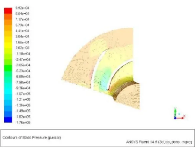
Figure 4K-Epsilon Realizable Model - 1035
rpm
Shows the velocity variation in the central
pressure acting in the different
parts.Fig.4.energy and dynamic
Studyofthevelocitycontours gives.Above Figure
4.Thisfunctionally flow equation in K-Epsilon
turbulence model analyzed in rotational wall
functions based to take a result to be done in static
pressure - initialization operating conditions are
1035rpm .maximum values accrue 1.18E4 pa.
Figure 5 K-Epsilon Realizable Model - 1150
rpm
Above Figure 5. this functionally flow equation
in K-Epsilon turbulence model analyzed in
23
done in static pressure - initialization operating
conditions are 1150rpm .Results achieved in
maximum values accrue 1.18e+4 pa.
Below Figure6.Thisfunctionally flow equation in
K-Epsilon turbulence model analyzed in rotational
wall functions based to take a result to be done in
static pressure - initialization operating conditions
are1065rpm. Results achieved in maximum values
accrue7.00e+06 Pa.
Figure 6 K-Epsilon Realizable Model - 1265 rpm
2. K-EPSILON RNG MODEL
In this functions of the s t a t i c
pressurevariationisuniform atrated discharge
1035rpm and 1150rpm ,1265 rpm are compared in
K-epsilon -RNG functional equation to apply
equation form analysis based analyzed model
butcomparatively non-uniformat otheroperating
conditions. Single Plane and single radial gap are
attached of casing for different operating
conditions. Shows the velocity variation in the
central pressure acting in the different parts. Fig
7.Ideaaboutthekineticenergy and dynamic
Studyofthevelocitycontours gives.
Figure 7 K-Epsilon RNG Model 1035 rpm
Above Figure7.This functionally flow equation in K-Epsilon turbulence model analyzed in rotational wall functions based to take a result to be done in static pressure - initialization operating
conditions are 1035rpm. Results achievedin
maximum values accrue 9.50e+04 Pa.
Figure 8 K-Epsilon RNG Model 1150 rpm
Above Figure8.Thisfunctionally flow equation
in K-Epsilon turbulence model analyzed in
rotational wall functions based to take a result to be
done in static pressure - initialization operating
conditions are1150rpm. Results achieved in
24
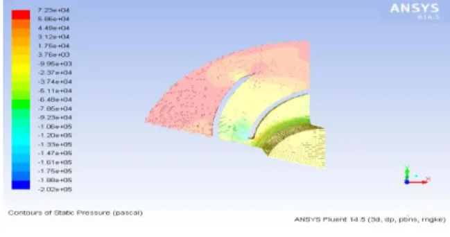
Figure 9K-Epsilon RNG Model1265 rpm
Above Figure 9. Thisfunctionally flow equation
in K-Epsilon turbulence model analyzed in
rotational wall functions based to take a result to be
done in static pressure - initialization operating
conditions are 1265 rpm. Results achievedin
maximum values accrue 7.23e+04 Pa.
3. K-EPSILON STANDARD MODEL
RESULTS
In this functions of the s t a t i c pressure variation
is uniform a trated discharge 1035rpm and 1150rpm
,1265 rpm are compared in K-epsilon -STD
functional equation to apply equation form analysis
based analyzed model but comparatively non-uni
format other operating conditions. Single Plane and
single radial gap are attached of casing for different
operating conditions. Shows the velocity variation
in the central pressure acting in
thedifferentparts.Fig.10 idea about the kinetic
energy and dynamic Study of the velocity contours
gives
Figure 10 K-Epsilon Std Model1035 RPM
Above Figure10.This functionally flow equation in K-Epsilon turbulence model analyzed in rotational wall functions based to take a result to be done in static pressure - initialization operating conditions are 1035rpm. Results achieved in maximum values accrue 8.00e+05 Pa
Figure 11 K-Epsilon Std Model1150 rpm
25
Figure 12 K-Epsilon Std Model1265 rpm
Above Figure12.This functionally flow equation in K-Epsilon turbulence model analyzed in rotational wall functions based to take a result to be done in static pressure - initialization operating conditions are 1265 rpm. Results achievedin maximum values accrue 7.50e+04 Pa.
VI.CONCLUSION
The followingconclusionswere drawn
fromtheanalysis:
It was found that K-ε SST model provides
better result compared to other two models in the
rpm of 1035 and 1150.
Similarly in 1265 rpm K-εRealizable model
provides better result compared to other two
models.
The given operating conditions, slurry
impeller which executes the maximum static
pressure at K-ε Realizable model comparatively
K-ε RNG model and K-ε SST model.
REFERENCES
1. Bacharoudis E.C., Filios A.E.,
MentzosM.D.,MargarisD.P.,2008. Parametric study
of a centrifugal pump impeller by varying the
outlet blade a n g l e , The Open Mechanical
EngineeringJournal275-83.
2. HamkinsC.P. and BrossS., 2002. Use of
surface flow visualization methods in centrifugal
pump design, Journal
o f F l u i d s E n g i n e e r i n g 124314-318.
3. MedvitzR.B., Kunz R.F., BogerD.A.,
AdamJ.W., YocumA.M., Pauley,L.L.,
2002.Performance analysis of cavitating flow in
centrifugal pump susing multiphase CFD. Journal
o f F l u i d E n g i n e e r i n g 124377-383.
4. MuggliF.A.,EiseleK., Casey M.V., GulichJ.,
SchachenmannA., 1997. Flow analysis in a pump
diffuser-part 2:validation and limitations of cfd for
diff user flows, Journal of Fluids
Engineering119978-984.
5. PatelK. And RamakrishnanN., CFD analysis
of mixed flow pump. Spence R., Teixeira J.A.,
2009. A CFDparametricstudy of geometrical
variations onthepressure pulsationsand performance
characteristicsofa centrifugal p u m p . Computers
& Fluids381243–1257.
6. ZhouW.,ZhaoZ.,LeeT. S.,WinotoS.H.,2003.
Investigation of flow through centri fugal pump
impellers using computational fluid dynamics,
International Journal of Rotating Machinery9(1)49–
61.
7. Combès, J.F., "TestCaseU3:CentrifugalPump
26
Workshop on Turbo machinery Flow Prediction VII,
Aussois, jan4-7 , 1999.
8. ArularasanR. And Velraj R. 'CFD analysis in
a heat sink for cooling of electronic devices',
International Journal of The Computer, the Internet
and Management Vol. 16.No.3
(September-December, 2008) pp 1-11.
9. Mukesh Didwania, Gopal Krishan, Ravi
kant, 'Study and Analysis of Heat Transfer through
Two Different Shape Fins using CFD Tool',
International Journal of IT, Engineering and Applied
Sciences Research (IJIEASR) ISSN: 2319-4413
Volume 2, No. 4, April 2013.
10. PulkitAgarwal, MayurShrikhande and P.
Srinivasan,'Heat Transfer Simulation by CFD from
Fins of an Air Cooled Motorcycle Engine under
Varying Climatic Conditions', Proceedings of the
World Congress on Engineering 2011 Vol III WCE
2011, July 6 - 8, 2011, London, U.K.
11. J. John RozarioJegaraj, N. Ramesh Babu, A
strategy for efficient and quality cutting of material
with abrasive water jets considering the variation in
orifice and focusing nozzle diameter, Int. J. Mach.
Tools Manuf. 45(12-13) (2005) 1443-1450.
12. H. Liu, J. Wang, N. Kelson, R. Brown, A
study of abrasive water jet characteristics by CFD
simulation, Journal of Materials Processing
Technology 153-154(2004) 488-493.
13. M.G. Mostofa, K. Yong Kil, A. J. Hwan,
computational fluid analysis of abrasive water jet
cutting head, Journal of Mechanical Science and
Technology 24 (2010) 249-252.
14. Fluent User’s Guide, vol. 3, Fluent
Incorporated Publishers, Lebanon, 1998.
15. N. C. Markatos, “Modeling of two-phase
transient flow and combustion of granular
propellants.”International Journal of Multiphase