19
Fingerprint’s Core Point Detection using Gradient Field Mask
Ashish Mishra
Dr.Madhu Shandilya
Assistant Professor Associate Professor
Dept. of Computer Science, GGCT, Jabalpur, [M.P.], Dept. of Electronics .MANIT ,Bhopal[M.P.]
ABSTRACT
Fingerprint recognition is a widely used biometric identification mechanism. In case of correlation based fingerprint recognition detection of a consistent registration point is a crucial issue; this point can be a core point of a fingerprint. Many techniques have been proposed but success rate is highly dependent on input used and accurate core point detection is still an open issue. Here we discuss a core point detection algorithm which is computationally simple and gives consistent detection of a core point. The proposed technique is based on orientation field of the fingerprint which is calculated using gradient based technique and optimized neighborhood averaging to generate a smoother orientation field, on which we operate a specially designed mask for detecting core point as the orientation field in the region of the core point is different than the other area. Though all fingerprints don’t possess core point still this algorithm is useful to detect high curvature regions. This algorithm is helpful in the development of correlation based Automatic Fingerprint Recognition System (AFIS).
Keywords
: Fingerprint Recognition, Orientation Field,
Core Point Detection, Orientation Field mask.
I.
INTRODUCTION
Fingerprints are the oldest and most widely recognized biometric trait. All human being posses fingerprint and these fingerprints are result of unique ridge and valley structure formed by skin over the fingers [1]. Ridges and valleys are often run in parallel; these structures have bifurcation and ridge endings called as termination. The ridge structure as a whole takes different shapes, characterized by high curvature, terminations, bifurcations, cross-over etc. These regions are called singular regions or singularities. These singularities may be classified into three topologies; loop, delta and whorl. What makes fingerprint unique is the distribution of such structures at local level. These are called as minutiae [2].
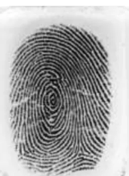
Fig.1. Typical fingerprint as scanned by optical fingerprint scanner
Minutiae mean small details and this refers to the various ways that the ridges can be discontinuous. A sudden ridge end is called
termination or it can divide into two ridges which is called bifurcations. Fig. 1 shows a fingerprint image.
Closer observation of such image can give us the location of present minutiae. Some of typical structures are shown in Fig. 2. We can see a ridge ending in Fig 2 (a), a core point in Fig 2(b). Fig. 2 (c) shows a ridge bifurcation. A loop present on a ridge is shown in Fig. 2(d)
(a) (b)
(c) (d)
Fig. 2 Typical Minutiae structures (a) Ridge ending (b) A core point. (c) Ridge bifurcation. (d) A loop present on a ridge
Automatic Fingerprint Identification Systems (AFIS) try to match fingerprint by matching these ridge valley structure. Mainly two types are systems are there (a) Minutiae based matching (b) Correlation based matching Minutiae based system try to identify the location and type of minutia and match it with database template. The accuracy is totally dependent on the identification of minutia point [3][4][5]. In case of correlation based techniques, rather than detecting minutiae, we go for global matching of ridge valley structure, here we try to match the texture of fingerprint. Such techniques are robust but less accurate [6][7][8].
Correlation Based Fingerprint Recognition
As discussed earlier the core point based techniques are robust, but for matching the global ridge structure, we need a consistent point for aligning the fingerprints. This point is called as Registration Point, the fingerprints have various ridge structures present on them, out of which the core points can be detected and used as Registration Point. In case of the fingerprint which don’t have core point we go for detection of point with high curvature regions or Low Coherence Strength. An example of Core point is shown in Fig.3.
20
Fig.3. Two fingerprints of same finger showing the core point. In [4] authors have described a fingerprint matching system based on Gabor filters, which uses circular tessellation around the core point and extracts Gabor Magnitude in 8 Directions, this is used as a feature vector, similar approach which uses a filter bank of Gabor filters is proposed in [5], they are using a set of filters to extract the fingerprint feature vectors and this is used for the training of classifier. In [6] Cavusoglu A. et al. , have proposed a robust approach which operates on grey levels of fingerprint and calculates global feature vector taking registration point at the reference. Success all these approaches is based on accurate determination of the core point (Registration Point). They have used various methods for determining the core point which are discussed in the next section.
II.
CORE POINT ESTIMATION METHODS
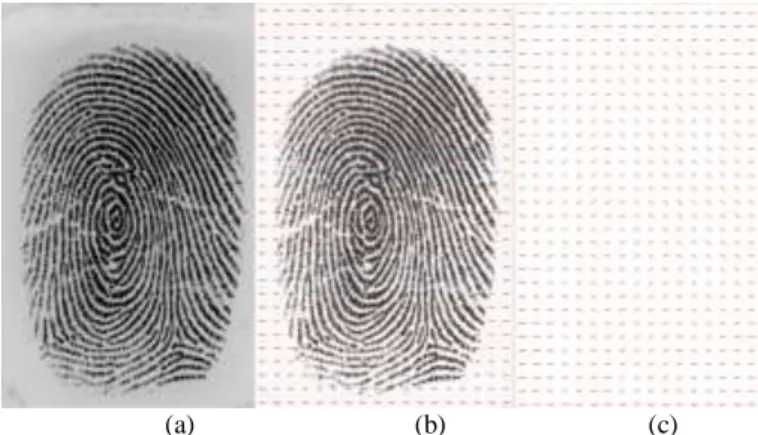
Core point detection is a non trivial task. To determine the location of the core point we first need to estimate the orientation field of the fingerprint. The orientation field is calculated blockwise for a fingerprint. In a W8W block of a fingerprint the direction of ridge is given by the orientation field, the orientation field estimation is itself a large area and various methods exist, here we have used our own method which uses a set of Sobel Gradient Masks and Orientation field is obtained by Optimized neighborhood averaging [11]. The orientation field obtained is fairly smooth; the orientation field angles are in the range of 0 to 180 degrees. The typical orientation field of a fingerprint is shown in Fig. 4, The core point detection is based on the orientation field calculation as all the methods are using the orientation field information to detect the core point.
Core Point Detection using Integration of Sine Component of the Fingerprint Orientation [5][6]
In this method the sine component of the orientation filed is integrated in a semi circular region, with three segments and the Components are linearly summed up in a specific manner as discussed in [14], this method give a good approximation of fingerprint but accuracy is still low, and for better approximation more number of iterations are required.
(a) (b) (c) Fig. 4. Fingerprint Orientation Map (a) Input Image (b) Orientation Field mapped over Fingerprint (c) Orientation Field Map
Core Point Estimation using Poincare Index [14]
This approach is based on calculation of Poincare index of all the points in orientation map, we actually determine the Poincare index by calculating the consecutive points field angle difference and summing it, the point enclosed by a digital curve (Core Point) will have highest Poincare index. The Poincare Index map is then thresholded and the point with highest value is taken as core point. This method is also used in [4] by Afsar F. et al. This method is also recursive, if no core point is found then the orientation field is smoothened and again the same procedure is followed. If still core point is not estimated then the authors have suggested a covariance based method, but this is computationally expensive. In the next section we propose our method which is using a mask to locate the core point.
III.
CORE POINT ESTIMATION USING
OREINATION MASK
This method is based on the fact that the core points are having specific pattern of the orientation field, the patterns appear like a loop formed in the region of core point. We are using a mask which gives maximum magnitude of convolution in the region of core point. An example of orientation field in the region of core point is shown in Fig. 5.
(a) (b)
Fig. 5. Orientation Field at the core point (a) Core Point (b) Loop Formed by the orientation field.
The angle in the region 1,3 have range of (45 to 90 degrees) and the angles in the regions have range of (0 to 45 degrees). If any
21
such pattern exists in a fingerprint it can be treated as a core point. We are using a mask which is empirically generated to locate such pattern in the orientation field and convolution with the orientation map gives maximum response at the location of core point or loop type regions. The mask is a 9 X 9 dimensional array shown below
1
1
1
1 0
1
1
1
1
1
1
1
1 0
1
1
1
1
1
1
1
1 0
1
1
1
1
1
1
1
1 0
1
1
1
1
0
0
0
0
0
0
0
0
0
1
1
1
1 0
1
1
1
1
1
1
1
1 0
1
1
1
1
1
1
1
1 0
1
1
1
1
1
1
1
1 0
1
1
1
1
OM
The after applying this mask at each element of the orientation map we get a magnitude which corresponds to the nature of orientation field around that point for a point O (i, j) in the orientation loop field this field strength is given by /2 /2 /2 /2
_
_
[ , ] [
,
]
y W x W x W y WLoop Field Strength
OM x y O i x j y
[1]
Where W is the mask size (W=9 in our case), we have developed this unique mask after observation of orientation fields of various fingerprints, this mask efficiently locates a complete loop if present in a fingerprint and locates the region of high curvature in case of the fingerprints which don’t have core point. The loop field strength is calculated for each element in the orientation map and next step is to threshold this magnitude array.
The algorithm for core point detection is given as follows:
1. Read the fingerprint Image
2. Normalize the fingerprint image to remove errors due to non uniform pressure and illumination while scanning of the fingerprint.
3. Estimate the orientation field by optimized neighborhood averaging.
4. Calculate loop field Strength at each point in the orientation field, using the developed orientation field mask.
5. Normalize the loop field strength array in a range of 0 to 1.
6. Threshold the loop field strength array to locate the core point, this threshold for our method ranges in the order of (.34 to .45). Take the centroid of the region if it consist of more than one blocks.
7. If more than one core points regions are located then take the region towards upper end or take centroid.
We discuss the results in the next section. For comparison purpose we use the Poincare index based method.
IV.
RESULTS
For testing purpose we have used images scanned using Fingerprint Scanner Futronics FS 88 which is meeting FBI standard for scanned fingerprint, the fingerprint is scanned at 500dpi and the size of image is 320 X 480 Pixels. Besides this the algorithm is also tested on fingerprints from Fingerprint Verification Competition [16][17] FVC 2000 and FVC 2002 Databases. We are using block size of 16X 16 for orientation field estimation and mask of size 8X8 for location of core point. The results are shown in table I. We have shown total five cases.
Case 1 and 2 show fingerprints having core (loop) in the ridge structure and corresponding detection results, In these cases our method gives best detection having distance between actual and the detected core ranging 5-10 pixels. In [6] authors are also using an empirical bias to compensate such error.
Case 3 and 4 show fingerprints not having core point but they possess high curvature loop like structure, we can take tip of such structure as registration point (reference) for correlation based matching. In this cases our algorithm has given the region containing the high curvature, the Poincare based mechanism needs iteration, we have shown the results for one iteration only, the method gives the region containing the core points but has more error, after performing more iteration location results can be improved.
In case 5 the fingerprint don’t posses any core point even the loop structure is not present, only curvature regions are there, error in our algorithm is more here, even the Poincare based method also cannot give the core point. For such cases another approach has to be followed, in [14] Jain A. K. et. al. have proposed using covariance based method locating registration point.
As far as the execution timings are considered both the methods take more are less same time. The Algorithm is implemented in Microsoft Visual C# 2.0, tested on a machine having AMD Athlon 64FX processor running at 1.8GHz and having 1.5 GB RAM. The operating system is Windows XP SP3 Processional. The timing measured was less than 50ms for both the algorithms. The accuracy of proposed method can still be improved by finding the coherence of fingerprint blocks inside the core point regions in case of the detected region is bigger. The coherence [13][15][16] is the gradient strength of the block, in case of high curvature regions the coherence is low as compared to other blocks, this property can be used to locate the core point accurately.
At this stage our proposed methods gives improvement over the existing method and the accuracy can still be improved.
22
TABLE I
RESULTS FOR CORE POINT ESTIMATION
Fingerprint Core Point Using Poincare
Index
Core Point Using Orientation Mask
Distance in pixels from Actual core point
1. FS 88 Scanner image Threshold =0.27 Threshold =0.35
Poincare – More than one Points
Orientation Mask - 10
2. FS 88 Scanner image Threshold =0.26 Threshold =0.36
Poincare – More than Regions Need Iterations Orientation Mask - 5
3. FS 88 Scanner image Threshold =0.25 Threshold =0.44
Poincare – 15 Pixels Orientation Mask – 20 Pixels
4. FVC 2002 DB1 image Threshold =0.25 Threshold =0.4
Poincare – More than Regions Need Iterations Orientation Mask – 5 Pixels
Poincare – More than Regions Need Iterations Orientation Mask – 25 Pixels Error is High as fingerprint does not have loop or core, only high curvature region is present.
23
5. 5.FVC 2004 DB1 image Threshold =0.26 Threshold =0.35
V.
CONCLUSION
In this paper we have proposed a novel method for core point detection, this method gives perfect detection of core point is a clear loop structure is resent on the fingerprint, in case of high curvature regions the accuracy is still better than existing method. The accuracy of proposed method can be further improved by combining given method with coherence parameter of the fingerprint. This algorithm is crucial in design of a correlation based fingerprint recognition system. This method can be used in existing system for better results or can be combined with existing method to improve accuracy.
REFERENCES
[1] Woodward, J. ,Orlans, P. , Higgins T.(2003), Biometrics, McGraw-Hill/Osborne
[2] Kekre H. B., Bhatnagar S. ,Finger Print Matching Techniques, In Proceedings of National Conference on Applications Digital Signal Processing. (NCDSP – 2007), Mumbai, Jan 19 – 20, 2007 [3] Maltoni ,D., Maio D., Jain A, and Prabhakar S.(2003), Handbook
of Fingerprint Recognition, Springer-Verlag
[4] Afsar F., Arif M. and Hussain M.(2004) , Fingerprint Identification and Verification System using Minutiae Matching , In Proceedings of National Conference on Emerging Technologies, Pakistan Institute of Engineering & Applied Sciences, Islamabad, Pakistan
[5] Jain A., Prabhakar S., Hong L, and Pankanti S.(2000) , Filter bank-Based Fingerprint Matching , IEEE: Transactions On Image Processing, Vol. 9, No. 5
[6] Cavusoglu A., Gorgunoglu S.(2007) , A Robust Correlation based Fingerprint Matching Algorithm for Verification, Journal of Applied Science, Vol 7, Asian network for Scientific Information : ISSN : 1812-5654
[7] Kekre H., Sarode T., Rawool V. (2008) , Finger Print Identification using Discrete Sine Transform (DST)”, In Proceedings International Conference on Advanced Computing & Communication Technology (ICACCT-2008), Asia Pacific Institute of Information Technology, Panipat India
[8] Kekre H., Sarode T., Thepade S. (2008) , DCT Applied to Column Mean and Row Mean Vectors of Image for Fingerprint Identification, In Proceedings International Conference on Computer Networks and Security (ICCNS08), Pune, India [9] Hong L., Jain A., Bolle R. (1997), On-Line Fingerprint
Verification , IEEE: Transaction on Pattern Analysis and Machine Intelligence, Vol. 19, No. 4.
[10]Hong L., Jain A. (1998), Fingerprint Image Enhancement : Algorithm and Performance Evaluation, IEEE: Transaction on Pattern Analysis and Machine Intelligence, Vol. 20, No. 8. [11]Kekre H. B., Bharadi V.A. (2009), Fingerprint Orientation Field
Estimation Algorithm Based on Optimized Neighborhood Averaging, 2nd International Conference on Emerging Trends in Engineering & Technology, Nagpur ,India
[12]Yu C., Xei M., Qi J. (2008), An Effective and robust Fingerprint Enhancement Method ,In Proceedings International Symposium on computational Intelligence and Design, IEEE: DOI – 10.1109/ISCID.2008.157
[13]Wang Y., Hu J., Han F. (2007), Enhanced Gradient Based Algorithm for the Estimation of Fingerprint Orientation Field, In Proceedings: Applied Mathematics and Computation 185(2007) 823-833, Science Direct: Elsevier.
[14]Jain A., Hong L.(2000), A Multichannel Approach for Fingerprint Classification ,In IEEE Transactions On Image Processing, Vol. 9, No. 5
[15]Bazen A. Gerez S. (2004), Directional Field Computation for Fingerprints Based on the Principal Component Analysis of Local Gradients, In Proceedings of 3rd International Conference
on Image and Graphics (ICIG ’04), The Netherlands
[16]Fingerprint verification Competition 2006, [WWW document]
http://bias.csr.unibo.it/fvc2006, (Accessed 25th March 2009)
[17]Maio D., Maltoni D. et. al. (2000), FVC2000: Fingerprint Verification Competition , Report of FVC 2000