Laboratory work #1
OPTIMIZATION OF LOAD DISTRIBUTION IN INTELLIGENT NETWORK
1.1 Purpose of work
The purpose of work is to get practical skills in solving a problem of optimal load distribution in Intelligent Networks for classical distributed, centralized and mixed (partially distributed) architectures of IN platform.
1.2 General information on optimal load distribution in Intelligent Networks
IN services will consist of services components, which are deployed in various nodes on the distributed platform and in principle, these components co-operate, invoking the services of each other, in order to support the various features of a particular service. Users request services, which means that the functionality of certain components is invoked. In turn, a component may invoke the services of other components depending on the task to be accomplished and the inter-component dependencies determined by the particular service. Each invocation imposes a certain load on the service node. The service nodes are physical elements where components may be installed. Each service node has certain capabilities, e.g. the maximum load it can undertake while keeping the performance within the acceptable range. In this respect, a reasonable constraint may be that certain components should not be deployed in the same service node. Then, however, an objective function is required, in order to guide the procedure that determines which service components should be deployed in the same service node. Classical examples in this respect are the cost of the communication among service components that are deployed in different service nodes. The set of constraints derives from the capabilities of the service nodes.
Based on the discussion so far the general problem statement is: Given a set of service components, the load they impose on a service node (obtained by the rate at which the components are being invoked and the load that each invocation imposes on the service node), a set of service nodes and their capabilities, find a distribution of traffic between IN nodes that results in the minimisation of the cost function (associated with the cost of communication among service components that are deployed in different service nodes, or load balancing among service nodes).
In the past, these optimisation algorithms have only been applied at the design stages of distributed control systems. Once the optimal allocation of resources to functionality had been determined, this allocation was intended to remain fixed for the lifetime of the network. As the optimal allocation is dependent on expected service demands at the time of design, the network may become sub-optimal as service traffic profiles change with time or as new service nodes or services are added to the network. In this case it would of advantage to re-optimise the distribution of traffic between IN nodes as service demands or functionality in the network change. It may also be necessary to integrate the re-allocation mechanism into load balancing algorithms.
Function allocation can be considered a design variable in distributed systems. The amount of inter-processor traffic depends on the allocation of functions amongst the processors and on the location of common resources required during call processing. Load balancing improves performance of distributed configurations by eliminating potential early bottlenecks.
The optimisation algorithm used in this work has been developed specifically for optimal distribution of load in Intelligent Networks with different architecture – from classical distributed to centralized one.
The object of this algorithm can be stated as follows: Given possible locations of the physical entities of a distributed system and the location of its users together with their service demands, find the load distribution between the functional entities (FEs) and physical entities (PEs) that minimises a particular cost. The cost may be decomposed into components such as communication cost, component installation cost etc. The algorithm, as described here, deals only with communication cost (for each pair of interacting components there is a communication cost if they are located in different physical entities) but the methodology described may be used to account for any combination of costs.
The optimal load distribution problem assumes the form of a combinatorial optimisation problem. The objective function to be minimised is a sum of the various costs. The objective function is accompanied by a set of constraints such as the service demand imposed by users. This demand constrains the traffic accepted by service initiation components. Additional constraints may appear due to finite channel capacities, finite processing capabilities, information and equipment ownership, technological shortcomings and the existence of administrative domains.
message and the total traffic exchanged between each pair of components is calculated and labels the graph edges.
A simple service, which consists of three FEs, as shown in figure 1.1, is to be deployed in the network. The labels on the graph edges denote traffic volume exchanged between entities for one unit of incoming traffic from the user.
SRF SCF
SSF
X=1 Z Y
U
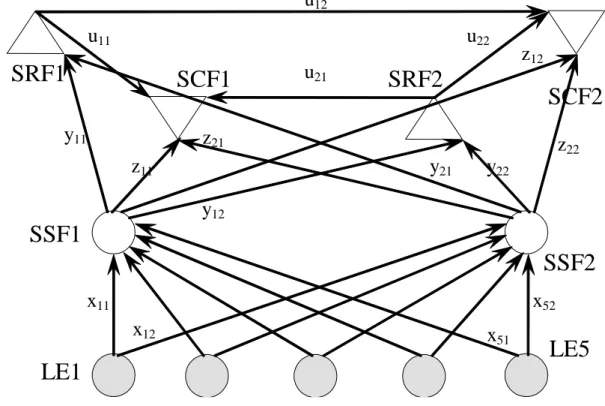
Figure 1.1 – A simple service, which uses three Functional Entities All FEs must be duplicated over all PEs in order to allow for their possible allocation to both PEs. The complete graph, together with the resulting variables, is depicted in figure 1.2. In order to avoid triple indices, variable names x, y and u have been used.
z12
y12
y21
z21
y22
z11
u21
z22
y11
x51
x12
x52
u22
u11
x11
u12
SRF
SCF1
SSF1
SRF1
SRF2
SSF2
SCF2
LE1
LE5
min , SRF -SCF -, SCF -SSF -, SRF --SSF , SSF -LE
j i ij ij j i ij ij j i ij ij j i ij ij u L z L y L x L f (1.1) subject to 0 ijx , for all i, j ; (1.2) 0
ij
y , for all i, j ; (1.3) 0
ij
z , for all i, j ; (1.4) 0
ij
u , for all i, j ; (1.5)
i j
ij
x
, for all i ; (1.6)
j i ij ij y u U Y, for all i, j i ; (1.7)
i ij j
ij Y x
y , for all i, j i ; (1.8)
i ij j
ij Z x
z , for all i, j i . (1.9)
When we have classical distributed architecture of the IN platform:
SSPj i
ij
x
, for all j ; (1.10)IPj i
ij
y
, for all j ; (1.11)SCPj i
ij i
ij u
z
, for all j . (1.12)When we have centralized architecture of the IN platform:
j SN SSCP i ij i ij i ij i
ij y z u
x
( )When we have combined (partly distributed) architecture of the IN platform:
IPj SSP i
ij i
ij y
x
, for all j ; (1.14)SCPj i
ij i
ij u
z
, for all j . (1.15)The constraint (1.6) express the service demand from the SSPs. Constraints (1.7)–(1.9) are derived for the service graph of Figure 1. Finally, the last (inequality) constraints set finite node capacities (formulas (1.10)–(1.15)).
1.3 Execution order
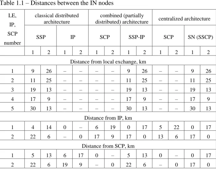
Input data for solving a problem of optimal load distribution in Intelligent Network are presented in tables 1.1-1.3.
Table 1.1 – Distances between the IN nodes
LE, IP, SCP number
classical distributed architecture
combined (partially
distributed) architecture centralized architecture
SSP IP SCP SSP-IP SCP SN (SSCP)
1 2 1 2 1 2 1 2 1 2 1 2 Distance from local exchange, km
1 9 26 – – – – 9 26 – – 9 26 2 11 25 – – – – 11 25 – – 11 25 3 19 13 – – – – 19 13 – – 19 13 4 17 9 – – – – 17 9 – – 17 9 5 30 13 – – – – 30 13 – – 30 13
Distance from IP, km
1 4 14 0 – 6 19 0 17 5 22 0 17 2 22 6 – 0 17 9 17 0 13 6 17 0
Distance from SCP, km
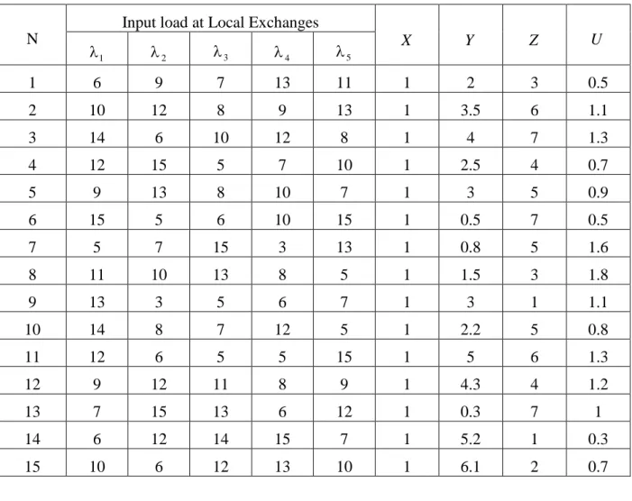
Table 1.2 – Intensity of IN services requests and traffic volume exchanged between entities for one unit of incoming traffic from the user
N
Input load at Local Exchanges
X Y Z U
1
2 3 4 5
1 6 9 7 13 11 1 2 3 0.5 2 10 12 8 9 13 1 3.5 6 1.1 3 14 6 10 12 8 1 4 7 1.3 4 12 15 5 7 10 1 2.5 4 0.7 5 9 13 8 10 7 1 3 5 0.9 6 15 5 6 10 15 1 0.5 7 0.5 7 5 7 15 3 13 1 0.8 5 1.6 8 11 10 13 8 5 1 1.5 3 1.8 9 13 3 5 6 7 1 3 1 1.1 10 14 8 7 12 5 1 2.2 5 0.8 11 12 6 5 5 15 1 5 6 1.3 12 9 12 11 8 9 1 4.3 4 1.2 13 7 15 13 6 12 1 0.3 7 1 14 6 12 14 15 7 1 5.2 1 0.3 15 10 6 12 13 10 1 6.1 2 0.7
Table 1.3 – Productivity of IN nodes
N
Productivity of IN nodes
classical distributed architecture combined (partly distributed) architecture
Continuation of tab. 1.3.
N
Productivity of IN nodes
classical distributed architecture combined (partly distributed) architecture
centralized architecture SSP IP SCP SSP-IP SCP SN (SSCP) 1 2 1 2 1 2 1 2 1 2 1 2 10 40 25 31 35 56 66 95 72 115 72 116 69 11 51 22 25 93 125 213 66 84 150 240 164 213 12 19 52 75 64 159 220 91 133 50 60 175 250 13 22 34 62 31 111 156 88 169 60 55 100 200 14 26 31 35 56 66 95 56 30 55 35 250 195 15 29 25 93 125 213 66 67 102 35 29 200 170
1.3.1 Write down the semantic and mathematical formulation of optimization problem solved in laboratory work for a given task variant for a classical distributed architecture of Intelligent Network.
– Write down a cost function, explain its physical meaning.
– Write down all the inequality restrictions, explain their physical meaning. – Write down all the equality restrictions, explain their physical meaning. 1.3.2 Compose a Matlab program solving a given problem (use a special function of Matlab optimization toolbox – linprog)
1.3.3 Execute a program, save the results.
1.3.4 Draw a resulting graph of intelligent network, point out the intensity if information flows between the functional and physical entities.
1.3.5 Repeat steps 1-4 for the combined (partially distributed) architecture. 1.3.6 Repeat steps 1-4 for the centralized architecture.
1.4. Contents of report
Report must contain: – purpose of work;
– input data for a given task variant;
– semantic and mathematical formulation of optimization problem solved in laboratory work for a given task variant including the complete graph of Intelligent Network;
– Matlab program used to solve a given problem; – results of program execution;
– resulting graph of Intelligent Network with intensities if information flows between the functional and physical entities;