ECE 35 Spring 2017
Homework #7 Solution
All homework problems come from the textbook, “Introduction to Electric Circuits”, by Svoboda & Dorf, 9th Edition. Question numbers in the 8th edition are listed for reference.
Question Number Svoboda & Dorf, 8th Edition Svoboda & Dorf, 9th Edition
1 P 7.8-8 P 7.8-8
2 P 7.8-11 P 7.8-11
3 P 8.3-3 P 8.3-3
4 P 8.3-5 P 8.3-5
5 P 8.3-10 P 8.3-10
6 P 8.3-13 P 8.3-13
7 P 8.3-14 P 8.3-14
8 P 8.3-15 P 8.3-15
9 P 8.3-19 P 8.3-19
10 P 8.3-20 P 8.3-20
11 P 8.3-22 P 8.3-22
12 P 8.4-1 P 8.4-1
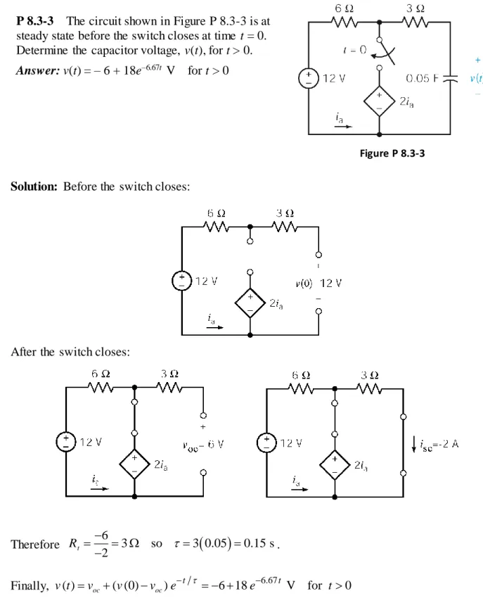
P 8.3-3 The circuit shown in Figure P 8.3-3 is at steady state before the switch closes at time t = 0. Determine the capacitor voltage, v(t), for t > 0.
Answer: v(t) = – 6 + 18e–6.67t V for t > 0
Figure P 8.3-3
Solution: Before the switch closes:
After the switch closes:
Therefore .
Finally, ( ) oc ( (0) oc) 6 18 6.67 V for 0
t t
v t v v v e e t
6
3 so 3 0.05 0.15 s 2
t
R
P 8.3-5 The circuit shown in Figure P 8.3-5 is at steady state before the switch opens at time t = 0. Determine the voltage, vo(t), for
t > 0.
Answer: vo(t) = 10 – 5e–12.5t V for t > 0
Figure P 8.3-5
Solution: Before the switch opens, vo
t 5 V vo
0 5 V. After the switch opens the part of the circuit connected to the capacitor can be replaced by it's Thevenin equivalent circuit to get:Therefore . Next,
12.5
( ) ( (0) ) 10 5 V for 0
t
t
C oc oc
v t v v v e e t
Finally, v0( )t v tC( ) 10 5 e12.5t V for t0
3
6
20 10 4 10 0.08 s
P 8.3-10 A security alarm for an office building door is modeled by the circuit of Figure P 8.3-10. The switch represents the door interlock, and v is the alarm indicator voltage. Find v(t) for t > 0 for the circuit of Figure P 8.3-10. The switch has been closed for a long time at t = 0–.
Figure P 8.3-10
Solution: First, use source transformations to obtain the equivalent circuit
for t < 0: for t > 0:
24
24
1 1 2
So 0 2 A, 0, 3 9 12 , = s
12 24
and 2 0
Finally 9 18 0
L sc t
t t
L
t L
L
i I R
R
i t e t
v t i t e t
Figure P 8.3-13
P 8.3-13 The circuit shown in Figure P 8.3-13 is at steady state when the switch opens at time t = 0. Determine v(t) for t ≥ 0.
Solution: Before t = 0, with the switch closed and the circuit at the steady state, the capacitor acts like an open circuit so we have
Using superposition
60 60
60 30
1 10 6 36 6 36 12 V
30 60 60 60 60 30 2 4
v
The capacitor voltage is continuous so v
0 v 0 12 V.After t = 0 the switch is open. Determine the Thevenin equivalent circuit for the part of the circuit connected to the capacitor:
oc
60
6 4 V 60 30
v
t 30 60 20 k
R
The time constant is R Ct
20 10 3
5 10 6
0.1 s so 1 10 1 s .
The capacitor voltage is given by
oc
oc
10 10
0 t 12 4 t 4 4 8 t V for 0
Figure P 8.3-14
P 8.3-14 The circuit shown in Figure P 8.3-14 is at steady state when the switch closes at time t = 0. Determine i(t) for t ≥ 0.
Solution: Before t = 0, with the switch open and the circuit at steady state, the inductor acts like a short circuit so we have
18 5
2 0.29 A 4 18 5 20 18 4
i t
After t = 0, we can replace the part of the circuit connected to the inductor by its Norton equivalent circuit. First, performing a couple of source transformations reduces the circuit to
so 2 0.25 1 51
10 s
The current is given by i t
0.29 0.4
e5t 0.40.4 0.11 e5t A for t0P 8.3-15 The circuit in Figure P 8.3-15 is at steady state before the switch closes. Find the inductor current after the switch closes.
Hint: i(0) = 0.1 A, Isc = 0.3 A, Rt = 40 Ω
Answer: i(t) = 0.3 – 0.2e–2t A t ≥ 0
Solution: At steady-state, immediately before t = 0:
10 120 0.1 A
10 40 16 40||10
i
After t = 0, the Norton equivalent of the circuit connected to the inductor is found to be
2 2
20 1
so 0.3 A, 40 , s
40 2
Finally: ( ) (0.1 0.3) 0.3 0.3 0.2 A
sc t
t
t t
L
I R
R
i t e e
Figure P 8.3-19
P 8.3-19 The circuit shown in Figure P 8.3-19 is at steady state before the switch closes. Find v(t) for t ≥ 0.
Solution: Before the switch closes v(t) = 0 so v
0 v 0 0 V.For t > 0, we find the Thevenin equivalent circuit for the part of the circuit connected to the capacitor, i.e. the part of the circuit to the left of the terminals a – b.
Write mesh equations to find voc:
Mesh equations:
1 1 2 1
2 1 2
12 10 6 0
6 3 18 0
i i i i
i i i
1 2
2 1
28 6
9 6 18
i i i i 1 1 2 1
36 18 A
2
14 1 7
= A
3 2 3
i i i
Using KVL, 3 2 10 1 3 7 10 1 12 V
3 2
oc
v i i
12 10 2 6 12 10 2
t
R
Then t 6 1 1 s 1 4 1
24 4 s
R C
and
oc
oc
4 4
0 t 0 12 t 12 12 1 t V for 0
v t v v e v e e t
P 8.3-20 The circuit shown in Figure P 8.3-20 is at
steady state before the switch closes. Determine i(t)
for t ≥ 0.
Solution: Before the switch closes the circuit is at steady state so the inductor acts like a short circuit. We have
1
24
0.8 A 2 5 20 20
i t
so
0 0 0.8 A i i After the switch closes, find the Thevenin equivalent circuit for the part of the circuit connected to the inductor.
Using voltage division twice
oc
20 1
24 7.2 V 25 2
v
t 5 20 20 20 14
R
oc sc t 7.2 0.514 A 14 v i R Then t
3.5 1 1 1
s 4
14 4 s
L R and
sc
sc
4 4
0 t 0.8 0.514 t 0.514 0.286 t 0.514 A for 0
Figure P 8.3-22
P 8.3-22 The circuit shown in Figure P 8.3-22 is at steady state when the switch closes at time t = 0. Determine i(t) for t ≥ 0.
Solution: Before t = 0, with the switch open and the circuit at steady state, the inductor acts like a short circuit so we have
0 0 4 A i i After t = 0, we can replace the part of the circuit connected to the inductor by its Norton equivalent circuit.
Using superposition, the short circuit current is given by
sc
8 3 8
2 4 3.75 A
8 5 3 3 8 5
i
t 8 3 5 16
R
so
2 1 1
0.125 s 8
16 s
The inductor current is given by
L sc sc
8 8
0 t 4 3.75 t 3.75 3.75 0.25 t A for 0
P 8.4-1 The circuit shown in Figure P 8.4-1 is at steady state before the switch closes at time t = 0. The switch remains closed for 1.5 s and then opens. Determine the capacitor voltage, v(t), for t > 0.
Hint: Determine v(t) when the switch is closed. Evaluate v(t) at time t = 1.5 s to get v(1.5). Use v(1.5) as the initial condition to determine v(t) after the switch opens again.
Answer:
0.5
2.5( 1.5)
for 0 1.5 s
5 5 V
( )
for 1.5 s
10 2.64 V
t t
t e
v t
t e
Figure P 8.4-1
Solution:
Replace the part of the circuit connected to the capacitor by its Thevenin equivalent circuit to get:
Before the switch closes at t = 0 the circuit is at steady state so v(0) = 10 V. For 0 < t < 1.5s, voc= 5 V and Rt = 4 so 4 0.05 0.2 s . Therefore
5
( ) oc ( (0) oc) t 5 5 t V for 0 1.5 s
v t v v v e e t
At t =1.5 s, v(1.5) 5 5e0.05 1.5 = 5 V.
Therefore
1.5 2.5 1.5
( ) oc ( (1.5) oc) t 10 5 t V for 1.5 s
v t v v v e e t
Finally
5
2.5 1.5
5 5 V for 0 1.5 s
( )
for 1.5 s
10 5 V
t t e t v t t e
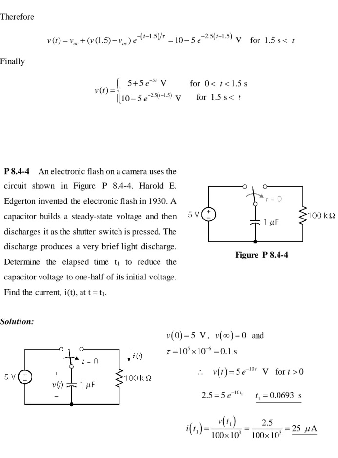
P 8.4-4 An electronic flash on a camera uses the circuit shown in Figure P 8.4-4. Harold E. Edgerton invented the electronic flash in 1930. A capacitor builds a steady-state voltage and then discharges it as the shutter switch is pressed. The discharge produces a very brief light discharge. Determine the elapsed time t1 to reduce the capacitor voltage to one-half of its initial voltage. Find the current, i(t), at t = t1.
Figure P 8.4-4
Solution:
0 5 Vv , v
0 and5 6
10 10 0.1 s
105 t V for 0
v t e t
1
10 1
2.55e t t 0.0693 s
11 3 3
2.5
25 A
100 10 100 10 v t
i t