ECE 35 Spring 2017
Homework #6
All homework problems come from the textbook, “Introduction to Electric Circuits”, by Svoboda & Dorf, 9th Edition. Question numbers in the 8th edition is listed for reference.
Question Number Svoboda & Dorf, 8th Edition Svoboda & Dorf, 9th Edition
1 P 7.2-2 P 7.2-2
2 P 7.2-10 P 7.2-10
3 P 7.2-12 P 7.2-12
4 P 7.2-13 P 7.2-13
5 P 7.2-15 P 7.2-15
6 P 7.3-4 P 7.3-4
7 P 7.3-5 P 7.3-5
8 P 7.3-6 P 7.3-6
9 P 7.4-2 P 7.4-2
10 P 7.4-6 P 7.4-6
11 P 7.4-8 P 7.4-8
12 P 7.5-12 P 7.5-12
13 P 7.5-16 P 7.5-15
14 P 7.6-3 P 7.6-3
15 P 7.7-7 P 7.7-7
P 7.2-2 The voltage, v(t), across a capacitor and current, i(t), in that capacitor adhere to the passive convention. Determine the current, i(t), when the capacitance is C = 0.125 F and the voltage
is v(t) = 12 cos(2t + 30°) V.
Hint: cos( ) sin ( ) ( )
sin ( )
cos
2
d d
A t A t t
dt dt A t A t
Answer: i(t) = 3 cos (2t + 120°) A
P 7.2-10 Determine v(t) for t ≥ 0 for the circuit of Figure P 7.2-10a when v(0) = –4 V and is(t) is the
current shown in Figure P 7.2-10b.
Figure P 7.2-10
P 7.2-12 The capacitor voltage in the circuit shown in Figure P 7.2-12 is given by 2
( ) 12 10 tV for 0
v t e t . Determine i(t) for t > 0.
P 7.2-13 The capacitor voltage in the circuit shown in Figure P 7.2-13 is given by
5
( ) 2.4 5.6 tV for 0
v t e t
Determine i(t) for t > 0.
Figure P 7.2-13
P 7.2-15 Determine the voltage v(t) for t > 0 for the circuit of Figure P 7.2-15b when is(t) is
the current shown in Figure P 7.2-15a. The
capacitor voltage at time t = 0 is v(0) = –12 V.
P 7.3-4 The current through a 2-μF capacitor is 50 cos(10t + π/6) μA for all time. The average voltage across the capacitor is zero. What is the maximum value of the energy stored in the
capacitor? What is the first nonnegative value of t at which the maximum energy is stored?
P 7.3-5 A capacitor is used in the electronic flash unit of a camera. A small battery with a constant voltage of 6 V is used to charge a capacitor with a constant current of 10 μA. How long
does it take to charge the capacitor when C = 10 μF? What is the stored energy?
P 7.3-6 The initial capacitor voltage of the circuit shown in Figure P 7.3-6 is vc(0–) = 3 V. Determine (a) the voltage v(t) and (b) the energy stored in the capacitor at t = 0.2 s and t = 0.8 s
when
5
3 A 0 1
( )
0 1s
t
e t
i t
t
Answer:
(a) 18e5t V, 0 ≤ t < 1
(b) w(0.2) = 6.65 J and w(0.8) = 2.68 kJ
P 7.4-2 Find the current i(t) for the circuit of Figure P 7.4-2. Answer: i(t) = –1.5e–250t mA
Figure P 7.4-2
P 7.4-6 Determine the value of the equivalent capacitance, Ceq, in the circuit shown in Figure P 7.4-6.
Answer: Ceq = 10 F
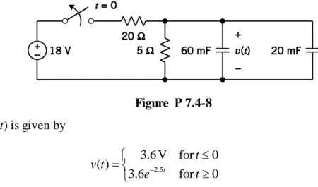
P 7.4-8 The circuit shown in Figure P 7.4-8 is at steady state before the switch opens at time t = 0.
Figure P 7.4-8 The voltage v(t) is given by
2.5
3.6 V for 0
( )
3.6 t for 0
t v t
e t
(a) Determine the energy stored by each capacitor before the switch opens. (b) Determine the energy stored by each capacitor 1 s after the switch opens.
The parallel capacitors can be replaced by an equivalent capacitor.
(c) Determine the energy stored by the equivalent capacitor before the switch opens. (d) Determine the energy stored by the equivalent capacitor 1 s after the switch opens.
P 7.5-12 The inductor current in the circuit shown in Figure P 7.5-12 is given by 8
( ) 6 4 tA for 0
i t e t
Determine v(t) for t > 0.
P 7.5-15 Determine the current i(t) for t > 0 for the circuit of Figure P 7.5-15b when
vs(t) is the voltage shown in Figure P
7.5-15a. The inductor current at time t = 0 is i(0)
= –12 A.
Figure P 7.5-15
P 7.6-3 The voltage, v(t), across a 25-mH inductor used in a fusion power experiment is
0 0
( )
6 cos100 0
t v t
t t
where the units of time are s and the units of voltage are V. The current in this inductor is zero
before the voltage changes at t = 0. Determine the power, p(t), absorbed by the inductor and the
energy, w(t), stored in the inductor.
Hint: 2(cos A)(sin B) = sin(A + B) + sin(A – B)
P 7.7-7 The circuit shown in Figure P 7.7-7 consists of 10 inductors having equal inductance,
L. Determine the value of the inductance L, given that Leq = 12 mH.
Answer: L = 35 mH
Figure P 7.7-7
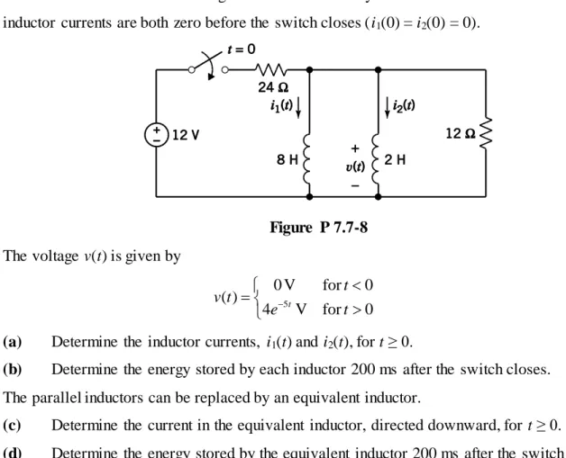
P 7.7-8 The circuit shown in Figure P 7.7-8 is at steady state before the switch closes. The inductor currents are both zero before the switch closes (i1(0) = i2(0) = 0).
Figure P 7.7-8 The voltage v(t) is given by
5
0 V for 0
( )
4 tV for 0
t v t
e t
(a) Determine the inductor currents, i1(t) and i2(t), for t ≥ 0.
(b) Determine the energy stored by each inductor 200 ms after the switch closes. The parallel inductors can be replaced by an equivalent inductor.
(c) Determine the current in the equivalent inductor, directed downward, for t ≥ 0.