Abstract— Earlier the use of air conditioning for comfort purpose was considered to be luxurious, but now-a-days, it is a essential for all human beings. Divided air conditioners, window air conditioners, are recycled in small buildings, offices etc. But, when requirement of cooling load is very high for big buildings such as multiplex, multi-story buildings, hospitals etc. Central air conditioners are used. Calculation of cooling load for building is important to find exact air handling unit and air conditioning equipment, to achieve good air distribution and comfort operation in the air-conditioned region. It must be taking into account the highest temperature in summer in the area. Building's location, construction's materials other interior's load must be considered for estimating accurate cooling load. All equations needed for heat transfer through the building and for the load are used to get the cooling load. Then, all equations are inserted in a personal package like M.S. Excel, to get the results.
Index Terms—
cooling load temperature difference, thermal load, comfort zone, cooling load factorI. INTRODUCTION
The main intend of Heating, Ventilation and Air Conditioning (HVAC) is to provide comfort for people and it allows humans comfort under adverse climatic conditions. Comfort is primary intent of HVAC systems.
It increases the productivity, building durability and health
[1]
. Air-conditioning is form of air treatment whereby temperature, moisture, freshening, sound, air velocity and air purity are all controlled within limits determined by the requirements of the air conditioned enclosure. For air conditioning the air conditioned space is maintained at a controlled temperature difference than the surrounding temperature [2] .The moisture content may also have to be maintained at a control level different than the atmospheric level so there has to be transfer of heat as well as ingression of moisture content from surroundings to the air conditioned space. Heat gains are either sensible, tending to cause a rise in air temperature or latent, causing an increase in moisture content. In comfort air conditioning sensible gain originate from the following sources
Solar radiation over and done with windows, walls & roofs
Manuscript received May, 2015.
V.K.Deepak, PG Scholar, Thermal Engineering, R.V.S. College of Engineering and Technology, Coimbatore, India, ph:.09809829021,
V.Murugan,Assistant Professor, Department of Mechanical Engineering, R.V.S. College of Engineering and Technology, Coimbatore, India.
S.Dhanaprabhu, PG Scholar, Thermal Engineering, R.V.S. College of Engineering and Technology, Coimbatore, India.
S.Manibharathi, PG Scholar, Thermal Engineering, R.V.S. College of Engineering and Technology, Coimbatore, India
Transmission through the building envelope & by the natural infiltration of warmer air from outside
People
Electric machines & the like
Latent heat gain is due to the presence of the occupants and the natural infiltration of more humid air from outside. In the case of industrial air conditioning there may be additional sensible &latent heat gains from the process carried out.[3]
All the above sources of heat gains are well researched but a measure of uncertainty is introduced by the random nature of some, such as a varying presence of people and the way in which lights are switched [4]. The thermal inertia of the building structure also introduces a problem when calculating the sensible heat gain arising from solar radiation. It follows that a precise determination of heat gain is impossible. Nevertheless, it is vital that design engineer should be able to calculate the heat gain with some assurance and this can be done when generally accepted methods of calculation are followed , supported by some commonsense[4].
The heat gain or loss is the amount of heat instantaneously coming into or going out of the planetary. The definite load is defined as that amount of heat which is instantaneously added or detached by the tools. The immediate heat gain and the actual load on the equipment will hardly be equal, because of the thermal inertia or storage effect of the building structure surrounding a conditioned space [5].
The current paper discusses about cooling Load Calculation. The cooling load calculation is for two floors of a showroom in a mall. The two floors constitute an area of 11845 ft² and each floor having a height of 11 ft.
II. BASIC INFORMATION
A. Building Location:
Calicut is a city in the state of Kerala in southern India on the Malabar coast at the longitude of 75.77°E and latitude of 11.25°N. Calicut is the third largest city in Kerala and is part of the second largest urban agglomeration in Kerala with a metropolitan people of 2,030,519.
B. Building Structures
Two floors of a building is considered for cooling load calculation. The two floors constitute an area of of
COOLING LOAD CALCULATION AND DUCT
DESIGN FOR A SHOWROOM
11845 ft² and each having a height of 11ft. The total area of glasses used a is 310 ft². The total wall area is 2902ft². Insulated glass of half inch air space with no indoor shading is used. Air space with four inch face brick is used in walls.
Figure 1. First floor
Figure 2. Seccond floor Table 1. Summary of building specifications
Item Description Unit 1 Total interior space (volume) 130,295 ft³ 2 Total exterior wall area 2,902 ft² 3 Total glass area 310 ft² 4 U factor for wall 0.36 5 U factor for glass 0.56
III. AIR CONDITIONING LOADS
In summer the air is cooled and the humidity will be removed from it. Room cooling load for summer consists of internal and external load. Both of them should be removed from the room to get a room temperature around 23°C-24°C with about 50% relative humidity, which is the zone of comfort for people.
3.1 Heat Gains:
External heat gains come from the transferred thermal energy from outside hot medium to the inside of the room. The heat transfer occurs through conduction through external walls, top roof and bottom ground, solar intensity through windows and doors, penetration and drying. Other sources of heat gained comprise people, electric tools and light.
Substances required calculating the thermal load of a place Zones of wrappers and glass
U-factors for the wrappers
Channel 'T” between inside and out side Glass transmission factors
Illumination density and connected factors
Engines and other temperature sources with related fa factors
Number of people and type of happenings Aeration rate and air enthalpy inside and outside 3.2 Heat Transfer Analysis
Heat is transmitted in or out of the building mainly through doors, windows, external walls, and through the top roof. The heat transferred through theses solid envelops are by transmission, convection and energy. The temperature difference for steady heat transfer, correction factor for solar intensity and unsteady heat transfer are to be measured. The construction cooling load is dependent on native weather, thermal appearances of material used, and building usage. To calculate the building freezing load, it typically requires a large and complex energy simulation computer program such as BLAST, DOE 2.1E.
HAP 4.3 or Elite which use the transfer function method and heat balance method to calculate the freezing load, correspondingly. This gentle of computer program usually requires local annual weather data (8760 hours) and requires a complex and drawn-out data input. Therefore, this kind of replication program is not very popular who prefer more compact and easy method for calculating the building freezing load. A extra simplified version for calculation of cooling load using the transfer function method is to use the one step procedure first presented in the 2005 ASHRAE
Handbook of Fundamentals. The method is now called the cooling load temperature differences (CLTD), solar cooling load factors (SCL), and internal cooling load factors (CLF) method.
This method makes hand calculation of cooling load possible. ASHRAE has developed the CLTD values for exterior walls and roofs based on solar radiation variation typical of 40°N latitude on July 21 with certain outside and inside air temperature conditions and based on building materials commonly used in North America. The correctness of the CLTD values could be in question when the location of the building is not at 40°N.Building material which does not match the ones used to generate the CLTD values by ASHRAE would also affect the accuracy of the cooling load calculated. LM is corrected factor for the locations other than 40°N latitude. Since Calicut is located on 11.25°N Latitude the value for LM is to take it for latitude of 24. K is correction factor depends on construction color. K=1 for dark in color building, 0.85 for medium color building and 0.65 for light building colour.
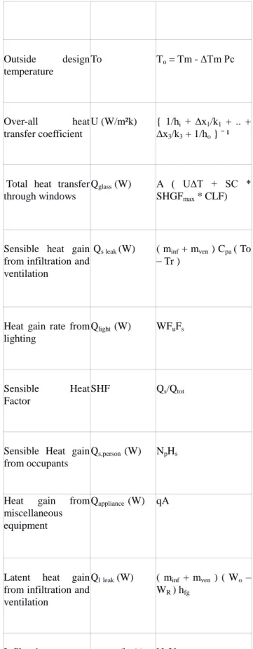
The Equations for cooling load estimations are shown in Table 2 below, where:
TR is room temperature.
To is the outside design temperature Tm is the maximum temperature at the day.
Pc : the maximum difference between maximum temperature and lowest temperature at the day
Np: number of people in the room V: volume filtration for one person
hR and hs : enthalpy of the room and the supply air The heat transfer through widows Q glass occurs by conduction, convection and radiation. Infiltration occurs because of gaps after windows, doors and walls owing to wind speediness, temperature change and door opening. Ventilation provides the cooling zone with fresh air for breathing and reducing CO2 and bad smelling.
Table 2. Equations for cooling load calculations
Descriptions Symbols Equations
Heat transferred through solids envelops Qw (W),Qr (W) AU∆T Temperature difference ∆T (°C) [ (CLTD + LM) K -(25.5 – TR) + (To – 29.4) ] Outside design temperature To To = Tm - ∆Tm Pc Over-all heat transfer coefficient U (W/m²k) { 1/hi + ∆x1/k1 + .. + ∆x3/k3 + 1/ho } ¯¹
Total heat transfer through windows
Qglass (W) A ( U∆T + SC *
SHGFmax * CLF)
Sensible heat gain from infiltration and ventilation
Qs leak (W) ( minf + mven ) Cpa ( To
– Tr )
Heat gain rate from lighting Qlight (W) WFuFs Sensible Heat Factor SHF Qs/Qtot
Sensible Heat gain from occupants
Qs,person (W) NpHs
Heat gain from miscellaneous equipment
Qappliance (W) qA
Latent heat gain from infiltration and ventilation
Qlleak (W) ( minf + mven ) ( Wo –
WR ) hfg
Infiltration rate minf (kg/s) Na Vp
ventilation rate mvent (kg/s) Np Vp
from occupants
Supply Air Quantity ma,s (kg/s) Qtot/(hR-hS)
Volume flow rate Vs (m3/s) ma,s Vs
Table 3. Constants
Symbols Descriptions
∆T percentage of temperature change at the time of cooling load calculation
CLTD Cooling load temperature difference.
LM corrected factor for the locations
K correction factor depends on building color
SC Shading coefficient
CLF cooling load factor for solar intensity from windows
SHGFmax Maximum solar heat gain factor.
NA Number of air change for the room per hour.
Vp
Ventilation rate per person
Hs Sensible Heat gain from occupants
Hl Latent Heat gain from occupants
Fu Lighting use factor, ratio of wattage in use to the total installed wattage
Fs Lighting special allowance factor,
Buildings are classified into fitted building, average and loose construction according to in infiltration rate. Infiltration rate, minf and aeration rate, mvent are calculated
by equation from table, 2.The heat gain from infiltration and ventilation or outside air consist from sensible heat due to temperature difference, Q s,leak and latent heat due to humidity ratio difference Q l,leak ,can be calculated using equations available in table 2. Glass is transparent so a large portion of sun's rays passes directly through it. The transmitted to the space takes time to diffuse within the space. This adds another factor depending on extra factors including colors & materials of equipment. The lights inside an air-conditioning space may contribute significantly to the total high temperature load. As the electronic power flows into the lamp, it causes other components of the lighting fixtures to heat up and ultimately diffuse further heat to the space. Depending on the type of lamps used, a factor needs to be added to the wattage of the lamp in order to get the total heat input. The lamps also heat up the furniture and other material in the building. Such heat is not diffused immediately and thus more factors affect the hourly heat gain. Accordingly, over-all factors had been derived for day to day use. Thus the Heat gain from lighting Q light is given by table 2.Equipment that produces heat within the space varies considerably according to the type and usage of the space, such as home applications, industrial equipment for workshops, cooking tools for restaurants, medical equipment for hospitals, etc. The heat can be sensible or latent or both. Due to the vast variety and sizes and due to their big share of the heat loads in some submissions “mainly public type services”, Ashrae additional institution published detailed lists of such appliances and the heat emitted from them. At least two approaches are likely. The first one is to carefully appraise the operating schedule and actual heat gain for each piece of equipment in the space. An alternative approach applicable for office spaces with a mix of printers, computers, copiers, faxes etc., is to estimate the equipment heat gain on a watt/m² source. People breathing or occupying the space add heat to it. Two types of heat are generated from people. One is sensible by direct heat transfer from the body “skin” to the space by convection due to temperature difference; the other is latent due to respiration. The rate of heat transfer depends on lot of factors and type of activities they perform.
Readymade table is obtainable for use, to choose the applicable type and multiply by the number of people to get the heat load. Total heat load is the abstract of the sensible heat with the total latent heat conversed formerly. By knowing the state of the supply air and the state of the room, the air quantity, ma,s required can be found by the energy balance on the space, see table 2. By knowing the specific volume of source air, vs from psychometric chart, the air volume flow rate required, Vs can be calculated.
IV. DUCT DESIGN
4.1 Calculation of duct size
1. First find out the air flow rate i.e. dehumidified air and cooling load.
installed.
3. Select initial velocity
4. Duct area = Air flow rate/ Velocity
5. Select duct size/dimension also Equivalent duct diameter. 6. Then initial friction rate is determined by using friction chart, on the basis of air quantity and equivalent duct diameter or velocity of air
V. RESULT AND TABULATION
All the equations mentioned above are inserted in a personal program like M.S excel to get results. The results show that the total cooling load for the two floors is 56.9 tons, distributed between the two floors as follows 1st floor 36.7tons and the second floor 20.3 tons. And the sensible heat factor for firs floor is 0.77 and that for second floor is 0.76. The ft²/ton for the building is about 208.172 ft²/ton, which is assumed to be high, comparing with what is standard about 100 ft²/ton
First floor Second floor
Area 7376.76 ft² 4468.38 ft²
Height 11 ft 11 ft
Lighting (Watts/sqft)
3 3
No. of air chnge required 1 1 cfm/person 10 10 No: of people 180 100 Outside air DBT/WBT 108°F/82°F 108°F/82°F Inside air DBT/WBT 73°F/61°F 73°F/61°F %RH outside/inside 50/45 50/45 Humidity ratio (GR/LB) 146/62 146/62 outside/inside Sensible heat Factor 0.77 0.76 Coil ADP 54°F 54°F Dehumidified rise 16.72 16.72 Dehumidified air cfm 11857 6543 Tons as per cfm 36.7 20.3 CFM/SQFT 1.61 1.46 Dehumidified CFM/TON 323.2 323.05 CFM/SQFT 1.61 1.46
AREA PER TON 201.08 220.62
RECTANGULAR DUCT AREA (ft) 4 * 3 3 * 2.6 CIRCULAR DUCT DIAMETER (ft) 4 3 FRICTION DROP (inches H2O per 100 feet) 0.03 0.04 VI. CONCLUSION
The cooling load calculation is done for two floors of a show room in a mall. According to the load analysis, suitable air-conditioning systems were selected for the building. Here cooling load temperature difference/cooling load factor (CLTD/CLF) method is used to determine the cooling load. For strictly manual cooling loads calculation method the most practical to use is the CLTD/CLF method. This method is simple to use, give component loads and tend to predict load on conservative side. Duct sizing and pressure drop in duct is calculated. Duct sizing is calculated by velocity reduction method. Pressure drop is calculated using duct friction chart by considering air volume flow and air velocity.
REFERENCES
1. Al-Rabghi,O. and Khalid A. , " Utilizing transfer function method for hourly cooling load calculations" Energy Conversion and Management,1997; 38: 319-332 2. Westphal,F.S. and Roberto L, " The use of simplified weather data to estimate thermal loads of non-residential buildings" Buildings,2004; 36: 847-854
3. Robert Parsons, ASHRAE HANDBOOK: Fundamentals. American Society of Heating; 2005.
4. Felix A. Uba, Emmanuel A. SarsahCooling Load Temperature Differential Values for Buildings in Ghana, International journal of science and technology research volume 2, issue 12, December 2013.
5. S.S.Wane and M.B. NagdeveDesign Of Air Conditionining System For College Auditorium, Journal of Environmental Research And Development, Vol. 6 No. 3, Jan-March 2012
6. K.W. Muia and L.T. Wong, Cooling load calculations in subtropical climate, Building and Environment 42 (2007). 7. Cooling And Heating Load Manual prepared by the American Society Of Heating, Refrigerating, And Air Conditioning Engineers,Inc
8. ASHRAE HVAC Fundamentals,1997 9. ASHRAE HVAC Fundamentals, 2005
10. R.S.Khurmi., J.K. Gupta., A text book of refrigeration and air conditioning,Eurasia Publishing House (P) limited 2011.
11. G.S. Sharma and B. Sharma. ―Duct designing in air conditioning system and its impact on system performance‖. VSRD International Journal of Mechanical, Automobile and Production Engineering, Vol. 2 No. 9 November 2012. 12. R. Whalley, A. A. Ameer. ―Heating, ventilation and air conditioning system modeling‖. Building and