Procedia Materials Science 6 ( 2014 ) 1226 – 1232
Available online at www.sciencedirect.com
2211-8128 © 2014 Elsevier Ltd. This is an open access article under the CC BY-NC-ND license (http://creativecommons.org/licenses/by-nc-nd/3.0/).
Selection and peer review under responsibility of the Gokaraju Rangaraju Institute of Engineering and Technology (GRIET) doi: 10.1016/j.mspro.2014.07.196
ScienceDirect
3rd International Conference on Materials Processing and Characterisation (ICMPC 2014)
Development and Characterization of Hard and Wear Resistant
MMC Coating on Ti-6Al-4V Substrate by Laser Cladding
Mandeep Dhanda
a,
Barun Haldar
b, P. Saha
c,*aLecturer, Rajiv Gandhi University of Knowledge and Technologies, IIIT Nuzvid,Pin-521202 A.P.,India b Associate Professor, Dept. of Mech. Engg., Birbhum Inst. of Engg. & Technology, Suri, Birbhum,Pin-731101, W.B.,India
cAssociate Professor, Dept. of Mech. Engg., IIT Kharagpur, Pin-721302, W.B.,India
Abstract
Ti-6Al-4V, due to its high specific strength and resistance to corrosion, is one of the highly useful materials in aerospace, automobile and chemical industries. Poor hardness and wear resistance properties restrict its further applications. So surface modification of Ti-6Al-4V is necessary surface to enhance its tribological properties. Multi-phase and multi component coating development is one of the present research trends in surface engineering arena. In the present study it was attempted to develop a multi-component coating by laser cladding process using a pre-placed powder mixture containing Ni5Al (50 vol%) + hBN (10
vol%) + B4C (20 vol%) + SiC (20 vol%) on substrate of Ti-6Al-4V to improve its tribological performance. A nano-structured
coating was formed with micro hardness (780 HV0.05). X-ray diffraction (XRD) identified the presence of compounds like TiC,
BN, TiB2, SiC, and intermetallics of Ni-Ti in the coating. The wear behaviour of the composite coating was assessed by ball on
disc type wear and friction monitor at 10 N load at 300 RPM taking a track diameter of 5 mm. Specific wear rate and coefficient of friction (μ) were found to vary from 0.6E-12 to 2.2E-12 m3/N-m and from 0.15 to 0.45, respectively, due to rubbing of coated
surface against tungsten carbide ball. The microstructure was explored by Scanning Electron Microscopy (SEM). © 2014 The Authors. Published by Elsevier Ltd.
Selection and peer-review under responsibility of the Gokaraju Rangaraju Institute of Engineering and Technology (GRIET).
Keywords: Laser cladding; Ti-6Al-4V; multi-component coating
1.Introduction
Whenever an engineering component is in motion with another contacting component, the contacting surfaces
___________
* Corresponding author. Tel.: +91-322-228-1926 ; fax: +91-322-228-2278 . E-mail address:[email protected]
© 2014 Elsevier Ltd. This is an open access article under the CC BY-NC-ND license (http://creativecommons.org/licenses/by-nc-nd/3.0/).
are subject to friction and wear. So the exposed surface needs high hardness, wear and corrosion resistance apart from low co-efficient of friction. Coating is a protective layer on a substrate and it can be applied in various ways like chemical vapor deposition (CVD), physical vapor deposition (PVD), sputter deposition, plasma coating, electro plating, nitriding, boriding, laser surface engineering and chemical displacement. Coating is often used to improve mechanical properties and increase corrosion resistance (Philip, 2006) of the substrate. Due to excellent process capabilities the laser cladding process is becoming popular in surface engineering industries. There are different laser cladding techniques (Gnanamuthu, 1976) like blown powder or powder injection methods, wire feeding techniques, rapid material deposition and preplaced powder method. Preplaced powder method is highly practiced in research studies due to the following reasons (Sampedro et al., 2011):
xa wide range of materials can be easily mixed and used,
xpowder loss is very less with respect to blown powder method,
xabsorption of laser powder at rough surface of the powder layer is higher which improves the process
efficiency, and
xthe process is less hazardous than blown powder method.
Titanium and its alloy are extensively used (Meng et al., 2006) in the aeronautical industries, engineering industries and bio-medical industries due to its high strength-to-weight ratio, excellent corrosion resistance and good thermal conductivity but it has very poor wear resistance. When a coating material with desirable properties is fused on the substrate by means of a laser beam, a thin layer of substrate gets melt and forms metallurgical bonding between substrate and coating material. However, a poor adherence may be observed because of surface contaminants and residual stress at the layer-metal interface (Yetim et al., 2010). The difficulty can be overcome by employing laser cladding of ceramic matrix composite coating on a titanium alloy substrate (Mossino et al. 2004)
(Liseicki and Klimpel, 2009). In addition, laser treatment has several other advantages over commonly used heat
treatment and spraying methods. These advantages include precise control over the width and depth of processing, ability to process complex parts, precise control of thermal input, thus yielding minimal dilution and a small heat affected zone.
In the present study investigations were carried out for developing multi-component MMC coatings on
Ti-6Al-4V substrate. It was aimed to obtain an in-situ multi-components-reinforced (TiN, TiB2, TiC, SiC) MMC coating
having favourable co-efficient of friction, higher hardness and wear resistance for various load bearing applications.
2. Experimental details
The powder mixture of Ni5Al (50 vol%) + hBN (10 vol%) + B4C (20 vol%) + SiC (20 vol%) was pre-placed
over the Ti-6Al-4V substrates having dimension (90×20×10) mm3.
Table 1. Composition of substrate material
Powders were mixed in a magnetic stirrer for 4 hours to get a homogeneous mixture of cladding materials. The powder materials were then mixed with 2% poly vinyl alcohol (PVA) solution and stirred to form a paste. The substrate was then polished with a SiC emery paper of grit size 600 mesh and cleaned with acetone. The semi solid paste of powder materials was then applied on the substrate with the help of coater machine in order to obtain desired uniform thickness of coating. The sample with the green coating placed in a muffle furnace for period of
about 10-15 minutes at a temperature of 150ᵒC for baking. The thickness of pre-placed powder mixture applied on
the coating was 200 μm and then finally, the samples were irradiated with the help of Ytterbium Fibre Laser
(YLR-2000) capable of delivering 2kW power having λ=1.06μm in CW energy delivery with spot diameter of 3mm in
argon shroud of pressure of 1.5 bar. The cladding tracks were formed by varying sets of parameters to optimize the
Element Ti Al V O Fe
power and the scan speed. Sufficient time was allowed for the samples to cool down to room temperature before the subsequent operation.
Fig. 1. photograph of laser cladding set-up. Table 2. Laser cladding process parameters
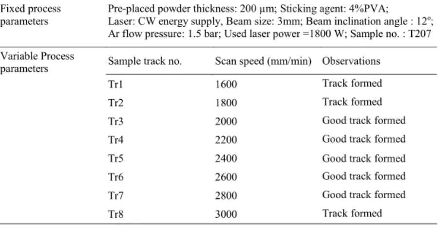
Fixed process
parameters Pre-placed powder thickness: 200 Laser: CW energy supply, Beam size: 3mm; Beam inclination angle : 12μm; Sticking agent: 4%PVA; o;
Ar flow pressure: 1.5 bar; Used laser power =1800 W; Sample no. : T207 Variable Process
parameters Sample track no. Scan speed (mm/min) Observations
Tr1 1600 Track formed
Tr2 1800 Track formed
Tr3 2000 Good track formed
Tr4 2200 Good track formed
Tr5 2400 Good track formed
Tr6 2600 Good track formed
Tr7 2800 Good track formed
Tr8 3000 Track formed
Following the laser cladding process, the samples clad tracks were cut by wire EDM machine to get required shape and size of sample for various tests. To explore microstructure of the coating, the samples were sliced and hot mounted by non-conductive phenolic resin. The hot mounted samples were mirror polished sequentially using SiC
grit 320 mesh → SiC grit 600 mesh → SiC grit 1200 mesh → Diamond grit 1 μm → Al2O3 grit 0.5μm → Colloidal
silica grit 60 nm. The samples were then etched with Keller’s reagent [HF (10 cc) + HNO3 (5 cc) + Water (85 cc)]
and prepared for SEM analysis. Micro structural analysis was done on the cross sections of all the samples using
SEM (scanning electron microscope) Model: Carl Zeiss Supra-40. Same specimens were used for micro-hardness
measurement. Different samples of dimensions 10×15×10 mm3 were used for XRD (X-ray diffraction) analysis
which was carried out by X’PERT PRO, 3040/60, PANalytic diffractometer with CuKα (λ=1.5418 Ả) radiation, so
as to identify the various constituent compounds present inside coating.
Ball on disc type wear and friction monitor with WC ball of 5 mm diameter and moving on 5 mm track diameter was used for determining co-efficient of friction and specific wear rate. Details of the experimental conditions are listed in table 3 and the calculations are based on the given equation.
Laser welding head (6 axis with CNC)
Shielding gas delivery nozzle
Table 3. Operating conditions used on ball-on-disc experiment for friction and wear measurement
3. Result and discussions
3.1. Microstructural analysis
3.1.1. EDS analysis
Table 4. EDS spectrum of sample
From EDS result of sample (fig. 3) it can be said that dark particles contains considerable amount of Titanium
Ball-on-disk experiment for friction and wear measurement Operating conditions
Tungsten carbide (WC) ball diameter: 5 mm Track diameter (2R): fixed (5 mm) Applied load: 10 N
Time of run: 30 min. Rotational speed: 300 rpm Specific Wear rate = [Wear volume / (Applied load × sliding distance)] (in m3/N-m)
Sliding distance = time × linear velocity = time × (π × track dia. × rpm) =140 m
Spectrum-1 Spectrum-2
Element Weight % Atomic% Element Weight % Atomic %
Ti 78.57 81.2 Ti 8.54 9.69 V 5.66 5.5 Al 2.71 5.47 Ni 15.77 13. Si 2.68 5.18 Ni 86.06 79.66 Coating Load Relative rotational motion WC Ball Coated sample R
Fig. 2.SEM micrographs of the transverse cross section showing coating thickness and cladding track deposited at
laser power 1.8 kW and scan speed 1800 mm/min.
Fig. 3.SEM micrographs showing EDS spectrum of sample deposited at laser power of 1.4 kW and scan speed 2800 mm/min laser power 1.8 kW and scan speed 1800 mm/min.
Spectrum 2 Spectrum 1
and light in colour particles, which may be called the matrix where reinforcement in black particles are present, contains considerable amount of Nickel. The phases, which are appearing as very light, may be Nickel aluminate as it is having highest average atomic weight. The phase, which is appearing as very dark, may be Titanium boride which may be further evident from the XRD analysis.
3.1.2. XRD analysis
Fig. 4. XRD profile of sample (Ti-207-1) processed at laser power 1.8 kW and scan speed 2000 mm/min.
XRD profile of specimen indicates that TiC, BN, TiB2, SiC, Ni-Ti are the major phases present in the clad
layer.
3.2. Micro-hardness test
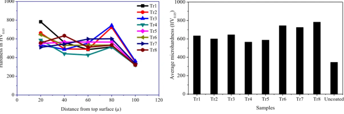
At a particular distance from top surface of the coating two readings were taken. The single point for each track is average of these two parallel readings and plotted in graph. Micro-hardness trends along the depth are shown in fig. 5. Fig. 6 shows different clad tracks (from Tr1 to Tr8) processed under different scan speeds (listed in Table 2).
0 20 40 60 80 100 120 0 200 400 600 800 1000 Hardness in HV 0. 05
Distance from top surface (P)
Tr1 Tr2 Tr3 Tr4 Tr5 Tr6 Tr7 Tr8 Tr1 Tr2 Tr3 Tr4 Tr5 Tr6 Tr7 Tr8 Uncoated 0 200 400 600 800 1000 Average microhardness ( + V0. 05 ) Samples
The overall trend indicates micro-hardness is slightly decreasing as moving towards substrate from top surface of
Fig. 5. micro-hardness value of different coating samples measured along transverse section.
Fig. 6. variation of maximum micro-hardness values with different scan speed.
the coating. It clearly shows that coating has a higher micro-hardness and there is sudden rise in peak. It may be due to the fact that indentation has encountered some hard inter-metallic phases or reinforced phases which are present in the coating.
3.2.1. Effects of input parameters on micro-hardness for various samples
The maximum hardness, having the value 780HV0.05, was achieved for this laser power (1800 W) at a scan speed
3000 mm/min. The variation of hardness against scan speed indicates that there could be an optimum operating regime of the input values. The effect of scan speed on hardening of coating material is shown in fig. 7.
Fig. 7. variation of average micro-hardness with heat input.
As it can be seen from the above figure that there is an optimum regime of heat input for which the maximum values of hardness can be obtained. As heat input was increased the dilution of substrate material might be increased. Presence of higher amount of substrate material in the coating matrix might cause softening of coating. On the other hand, higher scan speed causes rapid heating and cooling which may lead generation of finer grain size in microstructure. Finer grains of coating perform better in hardness and wear characteristics.
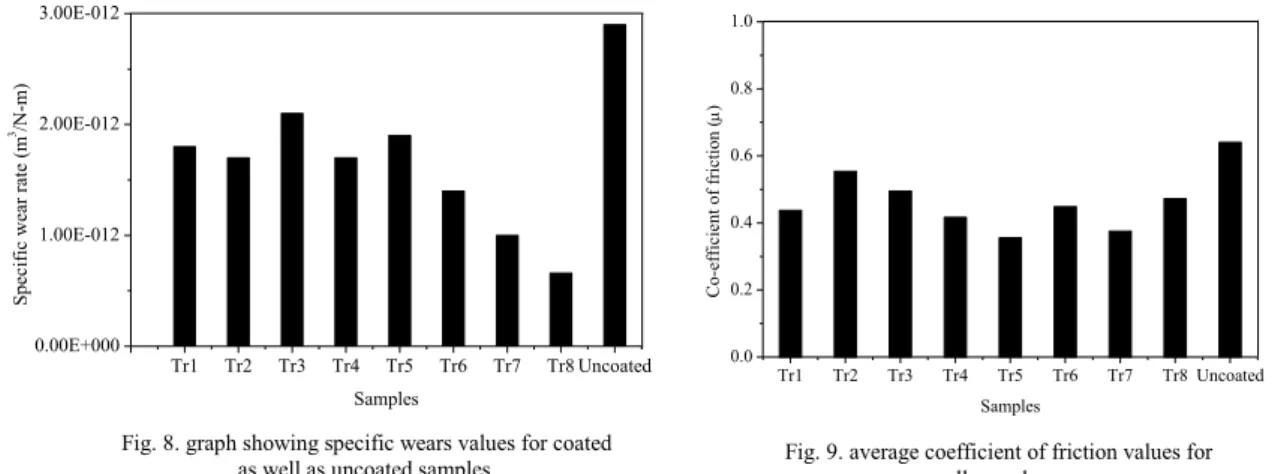
3.3. Wear tests
It can be seen from fig. 8 that sample 6, sample 7 and sample 8 exhibit lower wear rate. It may be attributed to the fact that these samples possess higher hardness along the cross section. The % decrease in specific wear value for almost all coated specimens is near about 50 % as compared to that for an uncoated sample.
Tr1 Tr2 Tr3 Tr4 Tr5 Tr6 Tr7 Tr8 Uncoated 0.00E+000 1.00E-012 2.00E-012 3.00E-012 Spe ci fic wea r ra te (m 3/N-m) Samples Tr1 Tr2 Tr3 Tr4 Tr5 Tr6 Tr7 Tr8 Uncoated 0.0 0.2 0.4 0.6 0.8 1.0 Co-e ffic ie nt of fric tion ( P ) Samples
Frictional resistance was estimated (fig. 9.) by determining the coefficient of friction occurring between the coated surface and a tungsten carbide ball in sliding contact with each other for different values of input conditions.
30 40 50 60 70 400 600 800 1000 Avera ge mic ro-ha rdne ss(HV 0.05 ) Heat input (J/mm)
Fig. 8.graph showing specific wears values for coated
4. Conclusions
It was aimed to develop a multi-component coating on Ti-6Al-4V surface by laser cladding technology using
preplaced powder mixture (consisting of Ni5Al, hBN, B4C, SiC) method to obtain a higher hardness and higher
wear resistance. As per the analysis, the followings results can be concluded.
xXRD analysis confirmed the presence of TiC, TiB2, NiTi2, B4C, SiC phases. No hBN was found in the
coating. It might be blown away and or reacted with titanium of diluted substrate (Ti-6Al-4V).
xSignificant improvement in micro-hardness was achieved in the coating at a maximum of 780 HV0.05 at the
coating cross section compared to 364 HV0.05 of the as received Ti-6Al-4V substrate.
xSpecific wear rate was reduced to about 50 % for some of the samples. Co-efficient of friction for the coating
varied from 0.15-0.45 for most of the samples.
References
Gnanamuthu, D.S., 1976, Cladding, US patent No.3952180, 219-121.
Lisiecki, A., Klimpel, A., 2009, Diode Laser Surface Modification of Ti-6Al-4V Alloy to Improve Erosion Wear Resistance, Archives of Materials Science and Engineering 32(1), 5-12.
Meng Q.W., Geng T.L. and Zhang B.Y., 2006, Laser Cladding of Ni-base Composite Coatings onto Ti-6Al-4V Substrates with Pre-placed B4C+NiCrBSi Powders, Surface Coating and Technology 200, 4923.
Mossino, P., Amato, I., 2004, In-situ Synthesis of TiC-TiB2-hBN-SiC Composites through SHS, Ceramics International 30, 2229-2233.
Philip, R., 2006, Alloying of Surface Layer of the Ti-6Al-4V Titanium Alloy through the Laser Treatment, Journal of Achievements in Materials and Manufacturing Engineering 15, 174-179.
Sampedro, J., Carcel, B., Ramos, J.A., 2011, Laser Cladding of TiC for Better Titanium Components, Physics Procedia12(A), 313-322. Yetim, A.F., Celik, A.F., Alsaran, A.F., 2010, Improving tribological properties of Ti-6Al-4V Alloy with Duplex Surface Treatment, Surface