Fuzzy Logic Based Advance Speed Control of Induction Motor
Debirupa Hore
Assistant Professor of Electrical Engineering Department
KJ Educational Institute‟s KJ College of Engineering Management and Research, Pune Maharashtra, India
Abstract--The speed control of Induction motor is done
using the advance AI Technique methods. In this System the vector control scheme in the stator flux oriented reference frame is used for controlling the
variable speed Induction motor. For this the
conventional Speed PI controller and Current PI Controllers are tuned and the responses are observed. The Conventional Speed PI Controller is then replaced by the Fuzzy Logic Speed Controller to observe the various responses of the system. The fuzzy Logic Speed Controller is designed and tuned in such a way to obtain better and fast sped responses of the system. Simulation results reveal that the fuzzy-controller improves the performance of variable speed Induction Motor in terms of speed and Power factor.
Index term-Induction motor speed, control,Vector control,AI techniques,Fuzzy logic
I. INTRODUCTION
AC Induction motors are being applied today to a wider range of applications requiring variable speed. Generally variable speed drives for Induction Motor (IM) require both wide operating range of speed and fast torque response, regardless of load variations. This leads to more advanced control methods to meet the real demand. To implement conventional control, the model of the controlled system must be known. The usual method of computation of mathematical model of a system is difficult.Usually classical control is used in electrical motor drives. The classical controller designed for high performance increases the complexity of the design and hence the cost. The operation of induction machines is much more complicated. Induction motors are coupled, non-linear, multivariable systems whose stator and rotor fields are not held orthogonal to one
another unlike DC motors ,which occurs to be a major problem in speed control of induction motor. The foregoing problem can be solved by vector or field oriented control. The vector control demonstrates that an induction motor can be controlled like a separately excited DC motor, brought a renaissance in the high performance control of induction motors. In order to achieve decoupled control over the torque and flux producing components of the stator currents Field Oriented Control is used. In the vector control, an AC machine is controlled like a separately excited DC machine. The machine control is considered in a synchronously rotating reference frame where the sinusoidal variables appear as DC quantities in steady
state. This paper investigates the performance of
variable speed Induction Motor through tuning of conventional PI as well as with fuzzy logic based Speed Controllers in MATLAB/SIMULINK environment [5]. II. VECTOR CONTROL SCHEME OF THE INDUCTION MOTOR
For an Induction Motor, one can assume three different perspective or frames of reference which are as follows:
1. Stator fixed reference frame (sd-sq)
2. Rotor reference frame (rα-rβ)
3. Stator flux oriented reference frame (x-y) In Vector Control scheme of the Induction Motor the three phase Rotor and Stator currents are converted to Stationary two phase current by (a-b-c) to (d-q) conversion using Clark‟s transformation equation. The current in the stationary reference frame is again converted to Stator flux oriented reference frame,(X-Y) frame. The currents in the (X-Y) frames are used to control the speed and Voltage respectively.
Fig 1-Frames of reference of induction motor drive Fig-2 Stator flux oriented Vector control of speed of Induction motor drive
A reference speed𝜔𝑟∗ is taken in the form of a constant
response. A reference Active Power Ps* is obtained from the error between the Reference Speed and the
Actual speed 𝜔𝑟of the Motor. A reference current Irx* is
derived from the error between reference and actual active power by tuning an Active current PI controller. Similarly a reference current Iry* is obtained from the error between reference and actual reactive power by tuning a reactive current PI controller. Both the reference Rotor currents are then transformed to a-b-c reference frame for implementing hysteresis PWM modulation. The Controlled Voltage obtained from the PWM Converter is then fed to the rotor for controlling the motor. The reference reactive Power Q* =0.
The speed control scheme has two Control loops. The inner current control loop and the outer speed control loop.
To transfer current from stator reference frame to rotor reference frame 𝑖𝑟∝+ 𝑗𝑖𝑟𝛽= (𝑖𝑑𝑠+ 𝑖𝑞𝑠) × 𝑒−𝑗 (𝜃𝑟 )…………... (1) In matrix form 𝑖𝑟∝ 𝑖𝑟𝛽 = cos θr sinθr −sinθr cosθr 𝑖𝑠𝑑 𝑖𝑠𝑞 ……… .. (2)
To transfer current from Flux oriented reference frame to rotor reference frame
𝑖𝑟𝛽+ 𝑗𝑖𝑟𝛽= 𝑖𝑟𝑥+ 𝑖𝑟𝑦 × 𝑒𝑗 (𝜌 −𝜃𝑟 )………… … (3) In matrix form 𝑖𝑟𝛼 𝑖𝑟𝛽 = cos(ρs −θr) cos(ρs −θr) sin(ρs −θr) sin(ρs −θr) 𝑖𝑟𝑥 𝑖𝑟𝑦 …… (4)
To transfer current from stator reference frame to Stator Flux oriented reference frame
𝐼𝑥+j𝐼𝑦= (𝐼𝑑𝑠+j𝐼𝑞𝑠) ×e−jρs……… ……….. (5) In matrix form 𝑖𝑥 iy = cos(ρs) sin(ρs) −sin(ρs) cos(ρs) 𝑖𝑑𝑠 𝑖𝑞𝑠 ……… (6) ……… (1) Again, 𝑉𝑠= 𝑉𝑠𝑥+ 𝑗𝑉𝑠𝑦……… (7)
In stator flux oriented reference frame
𝑉𝑠𝑥 = 0 𝑉𝑠 = 𝑉𝑠𝑦
Active and reactive power Equations Are
𝑃𝑠= − 3 2 𝐿𝑚 𝐿𝑠 𝑉𝑠 𝑖𝑟𝑦……… (8) 𝑄𝑠= 3 2 𝐿𝑚 𝐿𝑠 𝑉𝑠 𝑖𝑚𝑠− 𝑖𝑟𝑥 ……… (9) Where 𝑖𝑚𝑠= 𝑖𝑚𝑠𝑑 + 𝑗𝑖𝑚𝑠𝑞……… (10)
III. MODELING OF MOTOR
Fig-2 Equivalent circuit of motor
Considering the above figure following sets of equations are obtained for analysis of induction motor:
For the two-phase machine, we can write stator circuit operations as follows:
𝑉𝑞𝑠= 𝑅𝑠× 𝑖𝑞𝑠+ 𝑑 𝑑𝑡(Ψ𝑞𝑠)
𝑉𝑑𝑠 = 𝑅𝑠× 𝑖𝑑𝑠+𝑑𝑡𝑑(Ψ𝑑𝑠)……….. (11)
Where 𝜔 = 0 is considered, which gives the equations in
stationary form.
The flux linkage expressions in terms of the currents can be written from above figure as follows:
Ψ𝑞𝑚= 𝑋𝑀( Ψ𝑞𝑠 𝐿𝑠 + Ψ𝑞𝑟 𝐿𝑟) ……….. (12) Ψ𝑑𝑚 = 𝑋𝑀( Ψ𝑑𝑠 𝐿𝑠 + Ψ𝑑𝑟 𝐿𝑟 ) ……….. (13) Ψ𝑞𝑟 = 𝑉𝑞𝑟− 𝑅𝑟 𝐿𝑟( Ψ𝑞𝑟−Ψ𝑞𝑚) 𝑑𝑡……… (14) Ψ𝑑𝑟 = 𝑉𝑑𝑟− 𝑅𝑟 𝐿𝑟( Ψ𝑑𝑟−Ψ𝑑𝑚) 𝑑𝑡……… .(15) Ψ𝑑𝑠= 𝑉𝑑𝑠−𝑅𝐿𝑠 𝑠(Ψ𝑑𝑟 −Ψ𝑑𝑚) 𝑑𝑡…………(16) Ψ𝑞𝑠= 𝑉𝑞𝑠− 𝑅𝑠 𝐿𝑠( Ψqs−Ψqm) 𝑑𝑡………… (17) Where 𝑋_𝑀 = 1/(1/𝐿_𝑚 + 1/𝐿_𝑠 + 1/𝐿_𝑟 )
Motor currents in direct and quadrature axis are-
𝑖𝑞𝑟= Ψ𝑞𝑟−Ψ𝑞𝑚 𝐿𝑟 ……….. (18) 𝑖𝑑𝑟 = Ψ𝑑𝑟−Ψ𝑑𝑚 𝐿𝑟 ……….. (19) 𝑖𝑞𝑠= Ψ𝑞𝑠−Ψ𝑞𝑚 𝐿𝑠 ………. . (20) 𝑖𝑑𝑠= Ψ𝑑𝑠−Ψ𝑑𝑚 𝐿𝑠 ……….. (21)
∆𝐸
E
E
The torque equation from the motor can be derived as follows from which the speed of the motor is determined:
𝑇𝑒= 𝑇𝑙+ 𝐽 𝑑 𝜔𝑚 𝑑𝑡 = 𝑇𝑙+ 2 𝑃𝐽 𝑑𝜔𝑟 𝑑𝑡…………. (22) ∴ 𝜔𝑟= 𝑃 2𝐽(𝑇𝑒− 𝑇𝑙)𝑑𝑡………... (23) Again, 𝑇𝑒= 3 2 𝑃 2 𝐿𝑚 𝑖𝑞𝑠𝑖𝑑𝑟− 𝑖𝑑𝑠𝑖𝑞𝑟 ………… (24)
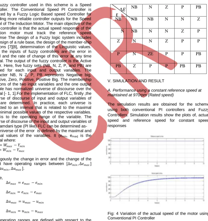
IV. DESIGN OF FUZZY LOGIC CONTROLLER
The fuzzy controller used in this scheme is a Speed Controller. The Conventional Speed PI Controller is replaced by a Fuzzy Logic Based speed Controller for providing more reliable controller outputs for the Speed control of The Induction Motor. The main objective of the fuzzy controller is that the actual speed response of the induction motor must track the reference speed response The design of a Fuzzy logic system includes the design of a rule base, the design of the member-ship functions [7][8], determination of the Linguistic values. Here, the inputs of fuzzy controllers are the error in speed and the rate of change of this error at any time interval. The output of the fuzzy controller is the Active Power. Here, five fuzzy sets (NB, N, Z, P, and PB) are adopted for each input and output variables. The Character NB, N Z, P, PB represents Negative big, Negative, Zero, Positive, Positive Big. The membership functions of the two input variables and the one output variable has normalized universe of discourse over the interval [- 1, 1].For the implementation of FLC, firstly ,the universe of discourse of input and output variables of FLC are determined. In practice, each universe is restricted to an interval that is related to the maximal and minimal possible values of the respective variables. That is to the operating range of the variable. The universe of discourse of the input and output variables of the Mamdani type (PI like) FLC can be determined as- The universe of the error is defined by the maximal and
minimal values of the variables. It {emin, emax] is the
interval where:
𝑒𝑚𝑎𝑥 = 𝑊𝑚𝑎𝑥− 𝑌𝑚𝑖𝑛 𝑒𝑚𝑖𝑛 = 𝑊𝑚𝑖𝑛− 𝑌𝑚𝑎𝑥
Analogously the change in error and the change of the
output have operating ranges between [∆𝑒𝑚𝑖𝑛, ∆𝑒𝑚𝑎𝑥]
and [∆𝑢𝑚𝑖𝑛, ∆𝑢𝑚𝑎𝑥]. Where, ∆𝑒𝑚𝑎𝑥 = 𝑒𝑚𝑎𝑥 − 𝑒𝑚𝑖𝑛 ∆𝑒𝑚𝑖𝑛 = 𝑒𝑚𝑖𝑛− 𝑒𝑚𝑎𝑥 ∆𝑢𝑚𝑎𝑥 = 𝑢𝑚𝑎𝑥 − 𝑢𝑚𝑖𝑛 ∆𝑢𝑚𝑖𝑛 = 𝑢𝑚𝑖𝑛− 𝑢𝑚𝑎𝑥
The operating ranges are defined with respect to the external values of the relevant variables. They can be further adjusted by taking into account the dynamics of the controlled systems and the sampling intervals.
For simplification and unification of the design of the FLC and its computer implementation, however it is more convenient to operate with normalizes universe of discourse of the input and output variables of the FLC. The normalized universes are well defined domains; the fuzzy values of input and output variables are fuzzy subsets of these domains. In general, the normalized universes can be identical to the real operating ranges of the variables, but in most applications they coincide with the closed interval [-1 1].Otherwise ,scaling of both input and output variables are done in order to bring the values within prescribed limit.
TABLE-1: Rule base for Fuzzy speed controller
NB
N
Z
P
PB
NB
NB
NB
N
N
Z
N
NB
N
N
Z
P
Z
N
N
Z
P
P
P
N
ZE
P
P
PB
PB
Z
P
P
PB
PB
V. SIMULATION AND RESULT
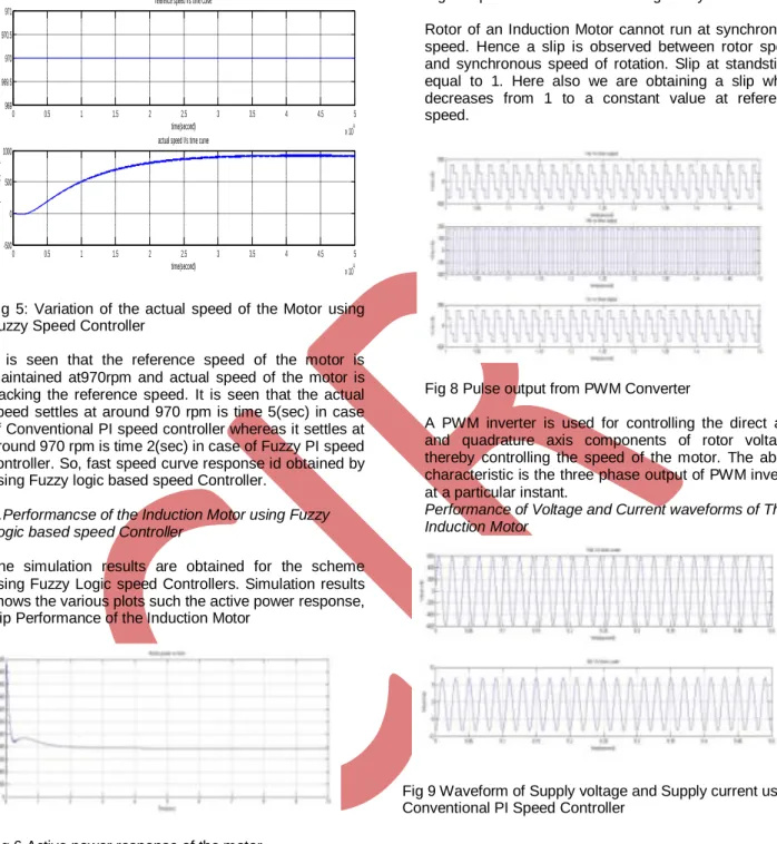
A. Performance using a constant reference speed at maintained at 970rpm (Rated speed)
The simulation results are obtained for the scheme using both conventional PI controllers and Fuzzy Controllers. Simulation results show the plots of, actual speed and reference speed for constant speed responses
Fig: 4 Variation of the actual speed of the motor using Conventional PI Controller
Fig 5: Variation of the actual speed of the Motor using Fuzzy Speed Controller
It is seen that the reference speed of the motor is maintained at970rpm and actual speed of the motor is tracking the reference speed. It is seen that the actual speed settles at around 970 rpm is time 5(sec) in case of Conventional PI speed controller whereas it settles at around 970 rpm is time 2(sec) in case of Fuzzy PI speed controller. So, fast speed curve response id obtained by using Fuzzy logic based speed Controller.
B.Performancse of the Induction Motor using Fuzzy Logic based speed Controller
The simulation results are obtained for the scheme using Fuzzy Logic speed Controllers. Simulation results shows the various plots such the active power response, slip Performance of the Induction Motor
Fig 6 Active power response of the motor
The motor is drawing an active power equal to the Rated Power 750 Watt.
Fig 7 Slip-time characteristics using Fuzzy controller Rotor of an Induction Motor cannot run at synchronous speed. Hence a slip is observed between rotor speed and synchronous speed of rotation. Slip at standstill is equal to 1. Here also we are obtaining a slip which decreases from 1 to a constant value at reference speed.
Fig 8 Pulse output from PWM Converter
A PWM inverter is used for controlling the direct axis and quadrature axis components of rotor voltages thereby controlling the speed of the motor. The above characteristic is the three phase output of PWM inverter at a particular instant.
Performance of Voltage and Current waveforms of The Induction Motor
Fig 9 Waveform of Supply voltage and Supply current using Conventional PI Speed Controller
Fig 10 Waveform of Supply voltage and Supply current using Fuzzy Logic Speed Controller
0 0.5 1 1.5 2 2.5 3 3.5 4 4.5 5 x 10⁴ 969 969.5 970 970.5 971
reference speed Vs time curve
time(second) r e f e r e n c e s p e e d ( r p m ) 0 0.5 1 1.5 2 2.5 3 3.5 4 4.5 5 x 10⁴ -500 0 500 1000
actual speed Vs time curve
time(second) a c t u a l s p e e d ( r p m ) 0 0.5 1 1.5 2 2.5 3 3.5 4 4.5 5 x 10⁴ 0 0.2 0.4 0.6 0.8 1 time(second) S li p
Slip Vs Time plot
3.5 3.55 3.6 3.65 3.7 3.75 3.8 x 10⁴ -600 -400 -200 0 200 400 600
Stator voltage Vs time curve
time(second) s ta to r v o lt a g e (v o lt ) 3.5 3.55 3.6 3.65 3.7 3.75 3.8 x 10⁴ -10 -5 0 5
Stator current Vs time curve
time(second) s ta to r c u rr e n t( A m p )
It is observed that using Fuzzy Logic Controller The supply Voltage and Supply current waveform are in phase with each other. It is ensured that the Power factor of the system is improved using a fuzzy speed Controller and the reactive Power requirement is also reduced.
VI. Conclusion-
A vector control strategy has been used in this paper for speed control of induction motor. The controlled parameters are first obtained in stator flux oriented reference frame. A hysteresis PWM current controlled method is used for generating the Voltage pulses. The pulse outputs of PWM converter are feed to the rotor in order to get desired and controlled speed response. The results were compared using a conventional Speed PI controller and fuzzy logic based speed controller. It was observed that with the aid of fuzzy speed controller better and faster speed control of induction motor is obtained. Also reactive power control is also possible by improving the power factor of the system.
References
[1.]Bimal K Bose condra, „Modern Power Electronics and AC Drives‟, Pearson Education, The University of Tennessee, Knoxvile..
[2].Peter Vas, „Vector control of AC Machines‟, Clarendon Press Oxford 1990.
[3]Dr. P S Bimbhra, „Power Electronics‟, Khanna Publishers.
[4]V.K Mehta,Rohit Mehta, „Principles of Electrical
Machines‟, S.Chand & Company Ltd.
[5]Ashok Kusagur, Dr. S.F Kodad, Dr. B.V Sankar Ram, „Modeling ,design and simulation of an adaptive Neuro-fuzzy interference system(ANFIS) for speed control of induction motor‟, International Journal of computer application,Septetmber-2010.
[6]J.P. Mishra, Debirupa Hore and Asadur Rahman, „Fuzzy logic based improved Active and Reactive Power
control operation of DFIG for Wind Power
Generation‟, National nstitute of Technology, Silchar, Assam, India.
[7] Arantxa Tapia, Gerardo Tapia, J.Xabier Ostolaza, and Jose Ramon Saenz, “Modeling and Control of a Wind Turbine Driven Doubly Fed Induction Generator”, IEEE Transactions. On Energy conversion, pp.194-204, 2003. [8]Badrul H. Chowdhury, Srivas Chellapilla, “Double –Fed Induction Generator Control for Variable Speed Wind Power Generation,” pp: 786-800, 2006.
[9]Ronald R Yager, Dimitar P Filev, “Essentials of Fuzzy Modeling and Control “Wiley Interscience Publications.
[10]Jun Yan, Michael Ryan, James Power “Using Fuzzy
Logic towards Intelligent systems‟‟.
[11]Hany M.Jabr, Narayan C.Kar, “Fuzzy Gain Tuner for Vector Control of Double-Fed Wind Driven Induction Generator”IEEE pp 2266-2269, May 2006.
[12]Chee Mun ong “Dynamic simulation of Electrical
simulation using Matlab/simulink” Prentice Hall PTR. J.G. Slootweg, H. Polinder, W.L. Kling, “Dynamic Modeling of the wind Turbine with Doubly Fed Induction Generator”, IEEE, pp: 644-649.