2.1. Scope
This section covers general gas service and gas meter-set requirements for residential and nonresidential installations.
2.2. Procedures for Establishing Gas Service 2.2.1. Establishing New Gas Service
Applicants must follow the steps described below to establish new gas service.
1. Applicant’s Planning Stage
When planning to establish new gas service, applicants must: 1. Fill out and submit the appropriate PG&E application. Refer to
Section 1, “General,” Subsection 1.3., “Application for Service Form,” on Page 1-3, for more information about the application requirements.
2. Contact their local PG&E service planners as early in the planning stage as possible.
NOTE:See the “2011 Service Planning Contact Information” at the
front of this manual on Page iv for specific contact numbers listed by area.
2. Working With PG&E
After initially contacting PG&E about installing new gas service, applicants must:
1. Submit details about the type(s) of gas appliance being installed. Include the connected load breakdown in standard cubic feet per hour (scfh).
2. Prepare a written justification for PG&E’s approval if the applicant is requesting more than 2 pounds per square inch gauge (psig) service delivery pressure. See Subsection 2.4.1., “Gas Pressure,” on Page 2-15 for more requirements.
3. Obtain approval from PG&E’s service planners for the gas service lateral and meter-set location. If the new gas service request is complex, PG&E may require that estimators and/or engineers become involved before approving the gas service lateral and meter-set location.
4. Select a trenching agent to perform the required trenching and paving services. The trenching agent also must obtain all of the permits required for installing the gas service pipe from the point of common connection at the main to the approved meter location. Applicants can select either PG&E or an outside contractor to perform this work.
If applicants select an outside trenching agent for the project, the applicant must obtain a copy of PG&E’s approved trench route or construction sketch. PG&E must inspect and approve any trenching and paving work performed by outside agents.
5. Pay PG&E for all of the installation costs. These include the costs for appurtenant facilities and fittings, valves, service pipe, service regulators, metering equipment, etc., in excess of the allowances. For more information, see PG&E’s Gas Rule 15, “Gas Main Extensions,” Section B, “Installation Responsibilities,” and,
Gas Rule 16 “Gas Service Extensions,” Section E, “Allowances and Payments by Applicant.”
6. Install, own, and maintain physical protection such as bollards or barrier posts and/or enclosures, as may be required.
3. Complying with Local Building Laws and Regulations
Applicants must contact local city and county deputies and inspectors to ensure compliance with all local laws and regulations. Applicants must:
1. Allow only qualified professionals to install applicant-owned facilities, including automatic shut-off devices. Also, applicants must ensure that valves required by local building codes, automatic shut-off devices, and safety devices are installed and inspected by local building inspectors.
2. Complete the required inspections on applicant-installed gas piping (e.g., houselines) and equipment (e.g., valves, appliances) before
2.2.2. Relocating an Existing Service
An applicant should contact PG&E as early as possible when he or she plans either to build an addition on an existing premises or to relocate an existing service to a different, acceptable location. Applicants are required to fill out and submit the PG&E Form 62-0687, “Application for Service, Existing Service–Relocate/Change Service.” This form is located on PGE.com at
http://www.pge.com/includes/docs/pdfs/mybusiness/customerservice/broch uresforms/app_62−0687_9−07.pdf. Information about this form also is located in Section 1, Subsection 1.3., on Page 1-3. The form requires applicants to provide the following information.
• Project Type: Asks the reason for the relocation/rearrangement.
• Project Information: Asks specific information about the project location and applicant.
• Contract Information: Asks for the applicant’s legal name, mailing address, etc.
• Representative Information: If the applicant has a legal
representative to relay project information and updates to the PG&E representative, this information goes here.
• Applicant Design and Installation Options: Lets the applicant know that either a qualified contractor or PG&E employee can design a new gas/electric distribution and/or service facility; however, the applicant will be charged for re-engineering changes if he or she makes changes after the initial selection.
• Construction Information: Describes the applicant’s choices for trenching and backfill work.
• Load Information: Asks for the number of existing meters at each service location and has an option for a gas pipe installer.
• Self-Generation and Net Metering Options: Describes the requirements to apply for PG&E’s net metering program.
• Attachments: Lists the documents required for the application including site improvement plans, drawings, and maps.
• Agreement to Pay and Signature: Applicants must sign the agreement and pay any fees associated with the work.
Applicants can choose to design and/or install services. They also have the option to provide trenching for gas services. The “Application for Service, Existing Service–Relocate/Change Service” form describes these options in greater detail.
If applicants decide to use PG&E after seeing the Company’s design bid, they will not be charged for re-engineering, if required. If applicants decide to use outside designers, PG&E will charge them for re-engineering costs if applicants change their decision on a trenching agent.
2.3. Gas Service Lateral
NOTE: All plastic gas distribution service pipes and stub completions must be a
minimum diameter of 1 inch for all new business installations. 2.3.1. General
A gas service lateral is the section of plastic tubing or steel pipe that connects the service riser and gas meter to PG&E’s gas distribution main. The gas distribution main usually is located in the street or in an easement located adjacent to the applicant being served. For more information, see Figure 2-1, “Typical Gas Service Installation,” below.
Lot Line
Gas Meter Gas Service Pipe
Gas Distribution Main Street or Roadway
Installation Costs Are Subject to Allowance Gas Service Pipe Riser Bldg.
Figure 2-1
Typical Gas Service Installation
1. When installing a gas service lateral on a residential service, PG&E will perform the following actions.
NOTE: While it is PG&E’s responsibility to install the gas service
lateral, the applicant has the option to install the service. 1. PG&E will install a service-lateral extension without charging the
applicant under the following conditions.
a. PG&E determines that the loads to be served are bona fide. b. The loads will be connected and the extension placed into
service within 6 months, and the gas rule allowances, based on applicant load, do not exceed the PG&E-estimated, installed cost of that extension. See PG&E’s [Gas Rule 16, Section E,
2. Determine the shortest and most practical route to an approved meter location to install the service lateral.
3. Install and connect the gas service lateral to the gas main in the adjoining street, highway, alley, lane, road, or easement.
4. Extend and connect the service lateral to the gas main on either side of the lot, at PG&E’s option, when the building or structure is located on a corner lot.
5. Install a utility excess flow valve, as required, when a new service lateral is installed. See Section 1, Subsection 1.13., “Installing Excess Flow Valves (EFVs) on Residential Services,” on Page 1-10, for more information.
NOTE:Refer to the current guidance and requirements
specified in Document A-93.3, “Excess Flow Valves.” 6. Install, own, and maintain the gas service lateral from its point of
connection with the gas main to the service delivery point.
2. When installing a gas service lateral, the applicant is responsible for the following actions.
1. Install and maintain all of the gas piping downstream of the service delivery point. See Subsection 2.5., “Applicant-Owned and
Installed Gas Service Piping (e.g., Houseline), Valves, and
Automatic Shut-Off Devices,” on Page 2-45, for more information.
NOTE:Applicants must refer to PG&E Form 79−716, “General
Terms and Conditions for Gas and Electric Extension and Service Construction by Applicant,” when they propose to install new gas services for new business utility services. This form is located on PGE.com in the Tariff Book at http://www.pge.com/tariffs/tm2/pdf/GAS_FORMS_79−716. pdf, under both #7, “Gas Forms,” and #8, “Electric Forms.” 2. Provide and maintain a clear route, free of any obstructions, for
installing the gas service facilities.
3. If PG&E determines that an applicant’s uninspected trench
excavation requires repair, or if the uninspected trench is backfilled and/or paved over, the applicant must provide and pay for all of the paving services and permits that are required to get an inspection and repair the trench excavation completely. This includes trenches dug on both public and private property.
4. Notify PG&E as soon as any paving activity is planned and provide PG&E with the scheduled completion date. Applicants should remember that PG&E can meet their schedules when the Company is notified early in the process.
NOTE:Service laterals must not go under or through buildings or
5. Provide and install an approved plastic casing (i.e., sleeve) under the paving material when the paving will extend over the gas service lateral. Applicants must ensure that:
a. The casing is made of a PG&E-approved material. Refer to Document A-75, “Gas Service and Mains in Plastic Casing,” which is located in Appendix B.
b. The casing is large enough in diameter to accommodate both the gas service pipe and the gas service riser, including the riser’s sun shield and a locating wire.
c. All of the requirements in the following PG&E documents are met. These documents are located in Appendix B.
• Document A-75, “Gas Service and Mains in Plastic Casing”
• Document A-81, “Plugs and Caps for Non-Pressurized Gas Pipelines”
• Document A-90, “Plastic Main and Service Installation”
• Document A-93.1, “Plastic Gas Distribution System Construction and Maintenance”
d. PG&E employees and equipment have sufficient, safe, and unobstructed access to the casing location with sufficient space to perform any required work when installing in a joint trench.
NOTE:For more information and illustrations, see
Utility Standard S5453, “Joint Trench,” Exhibit B, Joint Trench Configurations & Occupancy Guide, located in Appendix B of this manual.
e. The paving contains an opening or free space for the gas service riser when paving around the gas service riser. The opening must be at least 3 inches in diameter.
WARNING
To avoid potential accidents, do NOT begin to excavate before identifying underground facilities.
State law requires applicants to contact Underground Service Alert (USA) by dialing 811 before excavating, to request that member
companies locate and mark their underground facilities.
Applicants must contact USA to avoid damaging any existing underground facilities. Call USA at least 2 working days (excluding weekends and holidays) in advance for marking service. This service is free. More information is available from the USA North website at
3. PG&E does not permit the following types of installations. 1. Installing gas service laterals under or through buildings and
retaining structures.
2. Installing gas service laterals and gas service risers directly into concrete or asphalt pavement materials.
3. Installing gas service risers that are not approved by PG&E. 4. Installing gas service risers without an approved sun shield. 2.3.2. Branch Service Pipe
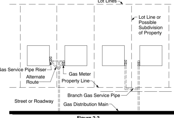
A branch service pipe is a pipe that branches off from a gas service pipe to serve two or more applicants.
A branch service usually is installed between two adjacent residential buildings that front on the same street and have meter locations on the sides of buildings that are adjacent to each other. Figure 2-2, “Typical Branch Services,” below, shows these types of risers.
Lot Lines Lot Line or Possible Subdivision of Property Alternate Route Gas Meter Property Line
Branch Gas Service Pipe Gas Distribution Main Street or Roadway
Figure 2-2 Typical Branch Services Gas Service Pipe Riser
If a right-of-way is not available, PG&E prefers that applicants provide a public utility easement (PUE) in which to install the branch service trenches. For more information, see Utility Standard S5453, Exhibit B, Joint Trench Configurations & Occupancy Guide, located in Appendix B of this manual.
Applicants must ensure that branch-service markers are installed over the service cock on each branch service. All branch services must be designed and installed as described in Document A-42, “Standard Branch Service Installation,” located in Appendix B of this manual.
2.3.3. Curb Valves
1. PG&E will install curb valves on services that supply buildings used for public assembly. Such buildings include:
• Theaters • Churches • Auditoriums • Arenas • Schools • Hospitals
2. PG&E may install curb valves on small, gas distribution systems, as well. These systems include:
• Mobile home parks (not individual mobile homes)
• Condominiums and apartments with private streets or ways
• Multiple buildings
• Shopping centers
• Commercial/industrial parks 2.3.4. Joint Utility Service Trenches
When installing underground electric service, PG&E’s service pipe and electric service lateral usually are installed in a common, joint trench. A joint trench mayinclude telephone and cable television facilities. When planning for joint trench installations that include telephone, cable television, or other facilities, applicants must be aware of the following requirements.
1. Additional lead time is necessary to plan and engineer a joint trench. 2. PG&E must review and approve the trench’s design details before
trenching begins and facilities are installed.
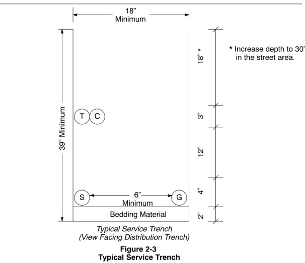
Figure 2-3, “Typical Service Trench,” on Page 2-9, shows the layout of a typical service trench.
Typical Service Trench (View Facing Distribution Trench)
18” Minimum 6” Minimum Bedding Material S G T C 39” Minimum 2” 4” 12” 3” 18” * Figure 2-3 Typical Service Trench
* Increase depth to 30” in the street area.
Note: For more information on Figure 2-3, see PG&E’s Joint Trench Configurations & Occupancy Guide, located in Appendix B.
Separation and clearance details for joint utility service trenches are located in Table 2-1, “Minimum Separation and Clearance Requirements for
Service Trenches,” below.
Table 2-1 Minimum Separation and Clearance Requirements for Service Trenches G Duct
T DBT C S P
(In Inches)
G Gas1 – 12 12 12 6 12
T Telephone (Duct) 12 – 1 1 12 12
T Telephone (Direct Bury) 12 1 – 1 12 12
C CATV 12 1 1 – 12 12
S Electric Secondary 6 12 12 12 – 3
P Electric Primary 12 12 12 12 3 –
SL Streetlight2 6 12 12 12 1 3
1 For more information about this table, see PG&E’s Joint Trench Configurations & Occupancy Guide in
Appendix B of this manual. Specifically, see Notes 4, 7, and 13.
2 Streetlight circuits not owned by PG&E must be installed to meet the requirements in PG&E’s Joint Trench
Configurations & Occupancy Guide. Specifically, applicants must review the requirements for working with a second utility company.
PG&E does not differentiate between the clearances for casing/conduit and pipe. The clearances and installation requirements are the same for both. For more information on the minimum separation and clearance
requirements for service trenches, see Engineering Material Specification Number 4123, “Backfill Sand,” in Appendix B.
When different service facilities (e.g., gas, electric, and telecommunications facilities) are installed in close proximity (e.g., in a joint trench), applicants must ensure that the facilities maintain a minimum horizontal separation of 12 inches where they transition from below ground to above ground.
1. PG&E allows exceptions to the 12-inch separation rule in the following circumstances.
1. Separation between PG&E’s secondary, electric service conduit and gas-service piping or casing may be reduced to 6 inches.
2. Clearances between other facilities can be reduced only when the parties supplying those services or facilities reach a mutual agreement.
NOTE:Applicants must ensure that sufficient space is
provided between facilities at all times to allow for safe maintenance and operation.
2. Applicants must not install enclosures for terminating or connecting telecommunication cables, wires, or other equipment within an area 12 inches above, and extending the entire width of, the gas meter, the service riser, and other service facilities.
3. Applicants must keep the area immediately behind gas meters, service facilities, and risers free and clear of all other facilities or equipment (e.g., pipes, wires, cables, building vents, or conduits). This requirement also applies to the area between those facilities and the premises or structure being served.
Before installing utility conduits or gas service piping, applicants must discuss the service arrangements and coordinate the meter locations and joint trench requirements with a PG&E service planner.
Applicants must ensure that the gas and electric meters are installed either adjacent to or in close proximity to each other. Refer to the following sections of this manual for acceptable electric meter utility locations.
• Section 5, “Electric Metering: General”
• Section 6, “Electric Metering: Residential”
• Section 7, “Electric Metering: Commercial and Industrial”
Wet-utility piping or facilities are not permittedin a joint trench. Examples of wet utilities that are not allowed in a joint trench include:
• Propane lines
• Pressurized water lines
• Sewer, sanitary, or storm drains
Utility Standard S5453, Exhibit B, Joint Trench Configurations & Occupancy Guide, located in Appendix B of this manual, describes the requirements for separating a wet utility from a joint trench.
When applicants want to install facilities in a joint trench other than those listed in this section, PG&E requires a written request that includes a justification for the exception. Applicants must submit their requests to PG&E for review and approval before beginning work on a joint trench. 2.3.5. Multiple Buildings Located on One Lot
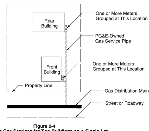
1. Two Buildings Located on One Lot
1. PG&E may furnish a separate gas service to each building if it does
not require an additional gas distribution main extension.
Figure 2-4, “Separate Gas Services for Two Buildings on a Single Lot,” located on this page, and Figure 2-5, “Separate Gas Services for Two Buildings on a Corner Lot,” on Page 2-12, show examples of two premises on one lot with separate gas services.
One or More Meters Grouped at This Location PG&E-Owned
Gas Service Pipe
Gas Distribution Main Street or Roadway Rear Building Front Building Property Line Figure 2-4
Separate Gas Services for Two Buildings on a Single Lot
One or More Meters Grouped at This Location
Building Building Gas Service Pipe
Possible Subdivision of Property
Gas Meter
Gas Service Pipe Riser
Property Line Gas Service Pipe
Property Line
Gas Distribution Main
Figure 2-5
Separate Gas Services for Two Buildings on a Corner Lot Lot Line Gas-Distribution Main Street or Right-of-Way Gas Meter
2. When more than one gas meter is required to serve a single
building, the meters for that building must be grouped at a common location that has been approved by PG&E. See Subsection 2.4.2.6., “Multiple Gas Meter Connection Requirements for Single and Double (Banked) Manifold Connections,” on Page 2-33, for grouping requirements when locations have multiple meters. 2. Three or More Buildings Located on One Lot
When two buildings, either single family or multifamily, are on the same lot and are located in close proximity to each other, PG&E may install a gas distribution main on the applicants’ properties. For specific requirements, see the Company’s main-extension rule, Gas Rule 15, and service-pipe extension rule, Gas Rule 16. Before a gas distribution main can be installed, applicants must ensure that the following conditions are met.
1. There must be a protected and accessible location on the property. 2. A satisfactory right-of-way, easement, or permit must be available
at no cost to PG&E.
Typically, PG&E installs a single, gas service pipe to each building, as described in Gas Rule 16.
Gas Distribution Main Meters 12 Unit Gas Service Pipe Meters
Gas Distribution Main Street or Roadway Gas Main Gas Main Gas Service Pipe Gas Main Lot Line Figure 2-6
Apartments With Grouped Meter Locations
Figure 2-7
Individually Metered Buildings Meters 6 Unit Gas Service Pipe 6 Unit Property Line 8 Unit 6 Unit Meters Gas Main
Gas Service Pipe Property Line
Bldg. Bldg. Bldg. Meter Meter Right-of-Way on Private Roadway Meter
Gas Service Pipe Riser
Typical Gas Distribution Main and Service Pipe Installation for Property With Three or More Buildings
Street or Roadway
Multifamily residential complexes are subject to a California Public Utilities Commission (CPUC) mandate specifying that each unit is metered individually. For more information, see Public Utilities Code, Section 780.5, found on the Internet at
http://www.legaltips.org/california/california_public_utilities_code/761
−788.aspx.
EXCEPTION: A single gas meter may serve an entire complex when the gas is used only for central heating systems (i.e., space, water) that supply all tenants in common, and when the tenants do not use gas appliances that require venting.
When each dwelling unit includes ground-floor space, each unit may have an individual service pipe and separate meter location if:
1. Sufficient meter space is provided.
2. Local ordinances do not prohibit such arrangements.
When it is practical, install the gas service pipe in a joint trench with the electric service.
When a multifamily residential complex consists of individually metered spaces, and not all of the units have ground-floor space, more than one service connection may be allowed if all of the following conditions are met.
1. An unreasonable burden, in PG&E’s opinion, will be placed on applicants if they are restricted to one service connection. 2. Service connections will be 150 feet apart or more.
3. Each service connection will provide service to a group of four meters or more.
4. The applicant pays for the entire length of the second (and any additional) service connection.
NOTE:For more information, see PG&E’s Gas Rule 16,
Section C.2, “Number of Extensions.”
5. Local code or ordinance allows for the multiservice arrangement. See Subsection 2.4.2.6. on Page 2-33 for specific requirements when locations have multiple meters.
2.3.6. Mobile Home Parks
Gas mains and services in mobile home parks must meet essentially the same standards for gas installations that are required for residential and nonresidential applications.
In addition, applicants must not install gas mains, services, and meters in the following areas.
• On steep slopes.
• In areas where landscaping restricts access.
• Under existing or proposed structures including mobile homes, porches, and stairs leading to porches.
Applicants should install the gas distribution mains in the roadway, when it is practical to do so, and in joint trenches, when it is feasible. On private property, ensure that rights-of-way are at least 10 feet wide for mains and at least 5 feet wide for service piping.
NOTE: Only use easements for utility installations. Table 2-1 on
Page 2-9 shows the minimum separation and clearance requirements for service trenches.
NOTE: Curb valves are not recommended for individual mobile
homes; however, a curb valve may be installed on a park’s community building.
2.4. Set Requirements for Gas Meters
A typical gas meter set with connected loads of less than 1,000 scfh includes:
• Gas meter
• Service regulator
• Gas shut-off valve
• Gas service-tee fitting (i.e., downstream bypass)
• All associated PG&E pipe and fittings
A typical gas meter-set with connected loads greater than 1,000 scfh includes:
• Gas meter
• Service regulator and possible monitor regulator
• Two gas shut-off valves
• Strainer or filter
• Bypass valve
• All associated PG&E pipe and fittings 2.4.1. Gas Pressure
The following information describes the three types of delivery pressure available with gas service.
1. Standard Delivery Pressure
PG&E typically will provide gas service pressure to the service delivery point at 7 inches of water column (WC). This is approximately 1/4 psig, as measured at the gas meter outlet.
2. Elevated Delivery Pressure
PG&E may be able to provide gas service at higher gas delivery pressures, depending on the location of the applicant’s facility and on the requirements of the gas system serving that location. PG&E maintains sole authority to determine if the elevated delivery-pressure service is available at a specified location.
In all elevated delivery-pressure service situations, PG&E reserves the right to reduce the gas service pressure to standard delivery pressure, as outlined in Gas Rule 2, “Description of Service,” when:
• The Company determines that the elevated gas pressure will no longer be available.
• The current delivery pressure is detrimental to PG&E’s gas distribution system.
NOTE: When providing elevated gas pressure service, PG&E can
incur additional costs. In these cases, special facilities charges will apply as described in Gas Rule 2. Applicants must pay these charges before PG&E can provide the services.
The following two numbered items describe cases where special facilities charges can apply.
1. For 2-psig Services: In many PG&E service territories with sufficient distribution operating pressure, 2-psig delivery pressure may be available to gas loads. When completing PG&E’s
“Application for Service” form, applicants must request 2-psig gas service delivery pressure in the “Load Information” section. In most cases, special facilities charges will not apply for a 2-psig delivery request. As mentioned previously, PG&E will determine if special facilities charges apply.
2. For Services Higher Than 2 psig: Elevated gas-metering pressures higher than 2 psig may be available from the local gas distribution system. PG&E must ensure that tapping into this existing service will not be detrimental to the operation of that gas system.
When requesting elevated gas service delivery pressure higher than 2 psig, applicants must follow these steps.
a. Contact local PG&E service planning employees as soon as possible (preferably in the planning stage for a new or remodeled building).
b. Fill out the appropriate PG&E “Application for Service” form and note the gas service delivery pressure being requested in the “Load Information” portion of the form.
c. Submit a formal, written request and justification for elevated gas service delivery pressure (e.g., the hypothetical houseline diameter size at standard delivery pressure, the appliances’ specification requirements).
d. Submit a houseline piping schematic.
e. Submit the manufacturer’s appliance specifications to ensure that the appliances will operate as designed.
3. Back-Pressure Protection
If an applicant chooses not to install pressure regulation, PG&E may require the applicant to install and maintain a check valve between the downstream (i.e., after) section of the meter and the upstream section of the applicant’s piping. This check valve prevents backflow. PG&E determines the need for check valves on a case-by-case basis.
For all higher-than-standard delivery pressure, PG&E recommends that applicants hire a qualified person, such as plumber or contractor, to review all of the applicant-owned gas piping, venting, and appliance installations for the gas pressure service being requested. The qualified person can ensure that the installations comply with all local, state, and federal codes, standards, and regulations. Specifically, the qualified person will help to ensure that the Uniform Plumbing Code is enforced based on the installation requirements of the local governing agency in the applicant’s location.
2.4.2. Gas Meter-Set Locations
Typically, PG&E provides only one meter set (in an outside location) for each dwelling unit and one service lateral to each building. PG&E may require that the meter be set at the property line if either of the following two conditions are met.
1. The building is back more than 200 feet from the property line.
2. A potential hazard or unusual site condition threatens the service lateral between the property line and the building.
PG&E requires that meter sets with connected loads greater than 1,000 scfh be located outside of and away from the building.
Any deviations require advanced approval from PG&E.
For specific information, see Gas Rule 16, Section C, Number 5, “Unusual Site Conditions.” Figure 2-8, “Property Line Installation,” located below, shows a property-line meter set installation.
Potential Hazard
Gas Meter Location and Meter Protection Provided by the Applicant
Gas Distribution Main Gas Service Pipe
Figure 2-8
Property Line Installation Building
Property Line
Street or Roadway
NOTE: PG&E must have unrestricted, drive-up access for service
1. Descriptions of Acceptable Meter Locations
The following three descriptions relate to locations acceptable for typical meter sets.
1. Outside Locations
An acceptable location for a typical meter set is outside of the structure in a readily accessible area that is protected from
corrosion and other damage such as vandalism. Do not place meters in areas where there is a high risk for vehicular damage, when possible. If meters must be placed in such areas, lessen the risk of vehicular damage either by installing the meter set away from the vehicular path or by placing barrier posts, also known as bollards, around the meter. See Subsection 2.4.2.7.6., “Additional Meter Set Requirements–Meter Protection,” on Page 2-42, for specific details on meter protection.
2. Breezeways
Breezeways that are adequately ventilated to the outside air and do
not allow gas to migrate into living spaces are acceptable meter-set locations. Where practical, ensure that one end of the breezeway is open to a large and unobstructed open space (e.g., street or
landscaping area) and the other end has at least two vents. Locate one vent at the top and the other vent at the bottom of the area to promote cross ventilation.
When the breezeway is not effectively open at either end, as a minimum, each end of the breezeway should have at least two vents located at the top and bottom of the area. These vents should be round and 3 inches in diameter. Each vent should provide a minimum net-free area of 4 square inches. Consider installing 3-inch by 8-inch vents, when practical.
3. Multiple Meters Located Either Outside or In a Breezeway
Where more than one meter is set at a premises, such as a multifamily unit or an apartment, set the meters at one location, except where it is impractical to do so. Locate the installed meters either outside of (this is the preferred location) or in a
well-ventilated breezeway.
2. Representative Figures Showing Acceptable Meter Locations for Various Premises
Figure 2-9, “Acceptable Locations for Gas Meter Installations,” on Page 2-19, and Figure 2-10, “Acceptable Meter Locations for Mobile Home Parks,” on Page 2-20, illustrate locations that are acceptable for installing typical meter sets.
1. Single Residential, Apartment, or Nonresidential Building
Property Line Rear Alley
Gas Distribution Main
Street or Roadway Acceptable Meter Locations
Gas Distribution Main
Building Building
Building Building
Figure 2-9
Acceptable Locations for Gas Meter Installations
Driveway Driveway Driveway Driveway
Gate
Gate
Gate
Gate
Gate
NOTE:When the meter set from the gas distribution line is located
in a rear alley, applicants should locate the meter set outside of any gated or fenced area. This allows easy access for PG&E employees when maintenance is required.
2. Mobile Home Parks
The mobile home park owner or operator must provide submetering facilities. Typically, meters are located on flat surfaces that are not obstructed by landscaping. Meter locations cannot be obstructed by understructures including mobile homes, porches, and stairs leading to porches. Figure 2-10 on Page 2-20 represents several acceptable meter locations within a typical mobile home park.
Gas Distribution Main Street or Roadway Meter Location Property Line Parking Figure 2-10
Acceptable Meter Locations for Mobile Home Parks Gate Porch Coach Patio Deck Gate Parking Canopy Over Parking Porch Parking Canopy Over Porch Canopy Over Porch
Acceptable Meter Locations
Porch
DeckPatio Garage Garage Site-Built Garage
PG&E will not provide metering facilities if they will be attached directly to a “movable” mobile home unit that is installed or set up in any location, including a mobile home park. Before PG&E will provide metering facilities, the mobile home must meet both of the following conditions.
a. Fixed in Place: The mobile home typically does not have either running gear or wheels and is not capable of being moved to another location.
b. Installed on a Foundation System: The mobile home must have a foundation system, as described in State of California Title 25, Division 1, Chapter 2, Article 7, Section 1333, “Foundation Systems.”
“If a mobile home park contains lots or site spaces that are set up to accommodate “movable” mobile home units, PG&E will install and supply the park using utility-approved service and metering facilities at a fixed location other than the mobile home. In these cases, applicants are responsible for connecting their mobile home units to those fixed metering facilities.”
3. Subsidence Areas
In subsidence areas, the acceptable location requirements are the same as the requirements outlined in Subsection 2.4.2.1.,
“Descriptions of Acceptable Meter Locations,” on Page 2-18. PG&E may install flexible connectors between the gas meter outlet and the houseline. These connectors may require additional
clearance space. See Figure 2-11, “Flex-Hose Meter
Set–Residential and Small Commercial,” located below, for a sample installation.
Figure 2-11
Flex-Hose Meter Set–Residential and Small Commercial Grade Service Riser Insulated Service Valve Regulator Applicant’s Houseline 1”
Front View Side View
R R
See Note 1 and Note 2
Precast Concrete Pad 12” x 12” x 3” Service Tee Owned and Installed by PG&E
Plugged Fitting
Plugged Fitting
Notes in reference to Figure 2-11.
1. The stainless-steel hose and braid is manufactured from a 2-foot flex hose.
2. The minimum centerline bend radius (R) for static bend is 2-1/8 inches for this flex hose. The maximum centerline bend radius is restricted to 6 inches for this length of hose.
4. Meter Rooms or Cabinets
If an applicant cannot provide an acceptable meter-set location either outside or in a well-ventilated location (e.g., breezeway), the applicant must install a meter room or cabinet where at least one wall is an exterior wall of the building. The meter room or cabinet should face a large and unobstructed open space. The service regulator vent(s) and separate hi-low room vents must terminate at a safe, outside location. Illustrations showing clearance
requirements are found in Subsection 2.4.2.5., “Minimum Clearance Requirements,” on Page 2-31.
3. Descriptions of Unacceptable Meter Locations
For new or remodeled buildings, do not locate gas meter sets in the following areas.
1. In curb meter boxes or vaults.
2. In living quarters, closets, toilet rooms, or bathrooms.
3. In garages without properly vented meter cabinets or enclosures. 4. Behind fences that applicants can lock.
5. Within engine, boiler, heater, or electrical-equipment rooms. 6. Under display platforms or show windows in commercial
buildings. (This includes any permanent, elevated display floors or platforms associated with the window where the purpose of the window is to present a display to the public.)
7. In contact with the soil, in a depression below general ground level, or where potentially corrosive materials are likely to contact the meter set.
8. In poorly ventilated breezeways.
9. In crawl spaces under buildings or decks, unless the crawl space is fully accessible for servicing and reading. (The crawl space must be well vented and the service-regulator vent must extend to an
acceptable outside location.)
10. Near a driveway or other traveled areas, unless the gas meter is adequately protected from passing vehicles as described in Subsection 2.4.2.7.6. on Page 2-42.
11. In a metallic cabinet, room, enclosure, or location that blocks or interferes with the radio frequency signal transmissions that are necessary for PG&E to operate its SmartMeter™ Advanced Meter Reading system.
12. In any location that provides less than 2 feet of clear working space in front of the gas meter, or as illustrated in Subsection 2.4.2.4., “Single Gas Meter Connection Requirements,” found below.
NOTE: All meter locations are subject to PG&E approval.
4. Single Gas Meter Connection Requirements
The figures beginning on Page 2-23 illustrate typical meter-set dimensions and working clearance requirements based on the total connected loads and stated delivery pressure.
NOTE: The actual meter-set configuration, including the
dimensions, may be different depending on field conditions and restrictions.
1. Figure 2-12 represents a typical gas meter kit with 0 through 350 scfh at 7 inches WC or 0 through 600 scfh at 2 psig.
Figure 2-12
Gas Meter Connection Using an AC-250 Gas Meter
Clear and Level Work Space
6” − 9”
12” 24” 12”
Top View
Building Finished Wall
ÑÑÑÑÑÑÑÑÑÑÑÑÑÑÑÑÑÑÑÑÑÑÑÑÑÑÑÑ ÑÑÑÑÑÑÑÑÑÑÑÑÑÑÑÑÑÑÑÑÑÑÑÑÑÑÑÑ ÑÑÑÑÑÑÑÑÑÑÑÑÑÑÑÑÑÑÑÑÑÑÑÑÑÑÑÑ Riser Location 4” Minimum Houseline Stub Out 24” 18”
2. Figure 2-13 represents a typical gas meter kit with 351 through 700 scfh at 7 inches WC or 601 to 1,340 scfh at 2 psig.
Figure 2-13
Gas Meter Connection Using an AL-425 or AC-630 Gas Meter
Clear and Level Work Space
6” − 9”
12” 30” 12”
Top View
Building Finished Wall
ÑÑÑÑÑÑÑÑÑÑÑÑÑÑÑÑÑÑÑÑÑÑÑÑÑÑÑÑÑ ÑÑÑÑÑÑÑÑÑÑÑÑÑÑÑÑÑÑÑÑÑÑÑÑÑÑÑÑÑ Riser Location 5” Minimum Houseline Stub Out 24” 18”
3. Figure 2-14 represents a typical gas meter kit with 701 through 1,120 scfh at 7 inches WC or 1,341 through 1,875 scfh at 2 psig.
Figure 2-14
Gas Meter Connection Using an AL-800 Gas Meter
Clear and Level Work Space
6” − 9”
12” 30” 12”
Top View
Building Finished Wall
ÑÑÑÑÑÑÑÑÑÑÑÑÑÑÑÑÑÑÑÑÑÑÑÑÑÑÑÑ ÑÑÑÑÑÑÑÑÑÑÑÑÑÑÑÑÑÑÑÑÑÑÑÑÑÑÑÑ Riser Location 6” Minimum Houseline Stub Out 24” 18”
4. Figure 2-15 represents a typical gas meter kit with 1,121 through 1,400 scfh at 7 inches WC or 1,876 through 2,400 scfh at 2 psig.
Figure 2-15
Gas Meter Connection Using an AL-1000 Gas Meter
Clear and Level Work Space
6” − 9”
12” 30” 12”
Top View
Building Finished Wall
ÑÑÑÑÑÑÑÑÑÑÑÑÑÑÑÑÑÑÑÑÑÑÑÑÑÑÑÑ ÑÑÑÑÑÑÑÑÑÑÑÑÑÑÑÑÑÑÑÑÑÑÑÑÑÑÑÑ Riser Location 6” Minimum Houseline Stub Out 24” 18”
5. Figure 2-16 represents a rotary gas meter with 1,401 through 3,000 scfh at an approved delivery pressure.
6’ 6” Minimum Headroom Required Double Gate or Removable Sections 4’ 0” 6’ 0” Figure 2-16
Gas Meter Connection Using a 1.5M or 3M Rotary Gas Meter
Enclosure Requirements By PG&E By Customer 2” Section A 15” 6” Meter Set 32” Finish Grade 1” 6” 4” 6” 16” 19” 17” 52” A
Provided and Installed
2” Flat Face Flange, ANSI 150, 4-Bolt
Notes in reference to Figure 2-16.
1. Customers must provide a 40x36x4 concrete pads with rebar in them and and 2” slip-on or weld neck flange.
2. If the set is built next to a building wall, place the vertical leg of the service pipe bend 20” from the wall. 3. The finish grade must be below the bury line marking on the service riser.
6. Figure 2-17 represents a rotary gas meter with 3,001 through 7,000 scfh at an approved delivery pressure.
Figure 2-17
Gas Meter Connection Using a 5M or 7M Rotary Gas Meter 6’ 6” Minimum Headroom Required Enclosure Requirements Double Gate or Removable Sections 4’ 0” 10’ 0” By PG&E By Customer 3” Section A Provided and Installed
3” Flat Face Flange, ANSI 150, 4-Bolt 32” 6” 15” 6” 6” 40” Maximum Meter Set 4” Finish Grade 1” A 90”
Notes in reference to Figure 2-17.
1. Customers must provide 78x36x4 concrete pads with rebar in them and 3” slip-on or weld neck flange. 2. If the set is built next to a building wall, place the vertical leg of the service pipe bend 20” from the wall. 3. The finish grade must be below the bury line marking on the service riser.
7. Figure 2-18 represents a rotary gas meter with 7,001 through 11,000 scfh at an approved delivery pressure.
Figure 2-18
Gas Meter Connection Using an 11M Rotary Gas Meter 6’ 6” Minimum Headroom Required Enclosure Requirements Double Gate or Removable Sections 4’ 0” 12’ 0” By PG&E By Customer 4” Section A 32” 6” 15” 6” 6” 47” Maximum Meter Set 4” Finish Grade 1” A 15” Service Space
Provided and Installed
4” Flat Face Flange, ANSI 150, 8-Bolt
106”
Notes in reference to Figure 2-18.
1. Customers must provide a 94x36x4 concrete pads with rebar in them and 4” slip-on or weld neck flange. 2. If the set is built next to a building wall, place the vertical leg of the service pipe bend 20” from the wall. 3. The finish grade must be below the bury line marking on the service riser.
8. Figure 2-19 represents a rotary gas meter with 11,001 through 16,000 scfh at an approved delivery pressure.
Figure 2-19
Gas Meter Connection Using a 16M Rotary Gas Meter 6’ 6” Minimum Headroom Required Enclosure Requirements Double Gate or Removable Sections 4’ 0” 12’ 0” By PG&E By Customer 4” Section A 32” 6” 15” 6” 6” NO TAG 47” Maximum Meter Set 4” Finish Grade 1” A 15” Service Space
Provided and Installed
4” Flat Face Flange, ANSI 150, 8-Bolt
106”
Notes in reference to Figure 2-19.
1. Customers must provide 94x36x4 concrete pads with rebar in them and 4” slip-on or weld neck flange. 2. If the set is built next to a building wall, place the vertical leg of the service pipe bend 20” from the wall. 3. The finish grade must be below the bury line marking on the service riser.
5. Minimum Clearance Requirements
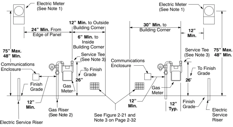
Figure 2-20, “Electric and Gas Meter Set Separation Dimensions and Clearances,” found below, Figure 2-21, “Gas Regulator Vent Spatial Clearance From Building Openings, Vents, and Windows,”on Page 2-32, and Figure 2-22, “Gas Regulator Vent Spatial Clearance Requirement From Sources of Ignition,” on Page 2-33, all represent various metering facilities’ spatial clearance requirements. If applicants install enclosures on their premises, the enclosures must meet the specifications provided in these illustrations.
Electric Meter
(See Note 1) Electric Meter(See Note 1)
12” Min. to Outside Building Corner 6” Min. to Inside Building Corner Service Tee (See Note 3) To Finish Grade Gas Meter Finish Grade Finish Grade Electric Service Riser 12” Min. Gas Riser (See Note 2) 24” Min. From Edge of Panel 30” Min. to Building Corner 75” Max. 48” Min. 75” Max. 48” Min. 12” Typ. To Finish Grade Service Tee (See Note 3)
Electric Service Riser
Gas Meter
Figure 2-20
Electric and Gas Meter Set Separation Dimensions and Clearances Communications Enclosure Communications Enclosure 12” Min. 12” Min. See Figure 2-21 and Note 3 on Page 2-32
26” 26”
Notes in reference to Figure 2-20.
1. Electric meter panel locations are subject to utility approval and must comply with the applicable code requirements. PG&E does not have specific requirements for the distance from the electric panel to the outside building corner. See Section 5, “Electric Metering: General,” for more information on properly locating the electric meters.
2. Place the gas riser 6 inches to 9 inches from the finished wall.
3. The completed houseline at the service delivery point must extend a minimum of 4 inches from the finished wall where the meter is to be set, and must be 26 inches above the finished grade. See Subsection 2.5. on Page 2-45 for more information. The houseline at the service delivery point typically is located after the PG&E service tee for residential services. The houseline must be reinforced so that it provides support for the meter-set piping. The pipe must be rigid, must be a minimum of 3/4 inches, and must have tapered pipe threads.
Figure 2-21
Gas Regulator Vent Spatial Clearance From Building Openings, Vents, and Windows
The minimum clearances do not apply to fixed windows that are not designed to open. 10’ 18” 18” Minimum Spatial Clearance CUBIC FEET
Building Vent Building Vent
Notes in reference to Figure 2-21.
1. Do not place vents under display platforms or show windows in commercial buildings. This includes any permanent, elevated display floors or platforms associated with the window, where the purpose of the window is to present a display to the public.
2. Do not place vents under building overhangs where the overhang is likely to direct venting gas to a building opening.
3. Locate the building vent openings below the level of the gas regulator vent termination and not behind the gas meter set.
Figure 2-22
Gas Regulator Vent Spatial Clearance Requirement from Sources of Ignition Pad-Mounted Transformers, Electric Equipment (Central Air) Combustion Air-Intake Vents 3’ Min. Combustion Exhaust Fan 3’ Min.
6. Multiple Gas Meter Connection Requirements for Single and Double (Banked) Manifold Connections
Specific requirements in this subsection apply to particular types of premises (e.g., multifamily, apartment, and commercial buildings) where multiple meters are installed at a single location using the manifold configuration. These manifold connection requirements are additions to the meter-set requirements for single gas meter sets. PG&E limits gas meter manifold configurations to one-tier or two-tier meter manifolds not exceeding 60 inches high. These manifolds are measured from the final, level, standing surface to the top of the manifold.
7.
Shut-Off Valve
Finished Ground Line
Single Manifold B A A A See Note 1 A A A A Shut-Off Valve A C A A A B Figure 2-23
Dimensions for Typical, Residential, Multimeter Installations Service Tee and Applicant
Houseline
14” Min. to Wall or Obstruction
Service Tee and Applicant Houseline
14” Min. to Wall or Obstruction
Banked Manifolds
Notes in reference to Figure 2-23.
1. Dimensions A and B may vary. Consult with the local PG&E service planner.
2. Typically, Dimension A is 12 inches for all installations except for multimeter cabinet installations, where Dimension A is 15 inches.
3. Typically, Dimension B is 26 inches for unenclosed installations and 32 inches for multimeter cabinet installations.
4. Dimension C is 24 inches for all installations.
5. The applicant’s houselines must be stubbed out 3 inches to 6 inches from the finished wall at the locations shown.
6. Clearly mark each houseline and meter position when they are hooked into multimeter installations. See Subsection 2.4.2.7.7., “Additional Meter-Set Requirement−Marking Houselines,” on Page 2-42.
NOTE: Applicants must obtain approval from the local PG&E
field services manager when planning to install manifold configurations that are larger than two tiers (e.g., three tiers). PG&E service planners will provide the contact information for the appropriate field service manager.
The local PG&E field services manager will assess the applicant’s site and conditions for gas service lateral and metering installations before approving an installation site. If the local field services manager
approves the site and allows an exception, the manager will provide the applicant with any additional requirements for installing and
7. Gas Meter Room and Gas Meter Cabinet Requirements 1. General Requirements
Applicants are responsible for furnishing and installing gas meter rooms or cabinets. They must ensure that all related vent openings, louvers, and/or viewing windows are installed correctly. These devices are required in meter rooms and cabinets to prevent gas from migrating into the building. Also, applicants must ensure that the meter rooms and cabinets are readily accessible to PG&E at all times. Refer to Document J-16, “Gas Meter Room,” located in Appendix B.
Typically, the gas meter size represented in Figure 2-12, “Gas Meter Connection Using an AC-250 Gas Meter,” located on Page 2-23, can be installed in a cabinet. Occasionally, PG&E will allow an applicant to install a gas meter the size of the one
illustrated in Figure 2-13, “Gas Meter Connection Using an AL-425 or AC-630 Gas Meter,” located on Page 2-24, in a cabinet;
however, this exception requires approval from PG&E. Applicants must install all other sizes of meter connections in a meter room, if an enclosure is required.
2. Specific Requirements for a Single Gas Meter Cabinet PG&E will determine the minimum cabinet size allowed for an applicant’s specific type of meter and provide the applicant with those dimensions. PG&E bases cabinet requirements not only on the size of the meter currently required, but also on the location and accessibility of the meter.
After receiving the general size requirements from PG&E, the applicant must consider the following requirements when determining the specifications for gas meter cabinets.
a. The meter must be accessible from a door that opens from the cabinet. A door that opens from the outside of the building is always preferred. PG&E must approve the design in advance if a meter-cabinet door does not open from the outside.
b. The cabinet door must be louvered or otherwise vented at the top and bottom. The door must be hinged at the side to permit it to open 90° or more. Also, PG&E requires an opening in the door that allows Company employees to read the meter index without opening the door.
c. In all cases, PG&E will install the shut-off valve on the service riser outside of the building at a readily accessible location.
d. Typically, PG&E will install the regulator on the outside of the cabinet. Applicants who want to install the regulator inside the meter enclosure must provide PG&E with justification.
Applicants must give PG&E time to consider the request before making a final determination as to whether the proposed regulator location meets Company construction standards and can be installed inside the cabinet.
e. The portion of the applicant’s houseline that connects to the gas meter facility is the only applicant-owned equipment or facility permitted inside the gas meter cabinet.
f. Do not place electric devices and connections for services such as cable television or telecommunications in the gas meter cabinet under any circumstances.
g. Cabinet installations also must comply with local ordinances, adopted codes, and requirements.
Figure 2-24, “Meter Cabinet Details,” found below, shows the dimensions and details for a single gas meter cabinet.
See Note 4 on Page 2-37 6” x 4” Read Window CL Bottom See Note 4 on Page 2-37 3”Approx. 10” Approx.
3”Approx. Gas Meter Cabinet Interior
4” 6”
Standing or Ground Level 1-3/16” Min. Dia. (See Note 2) 22”
Min. 1-3/16” Min. Dia.
2” x 4” Reinforcing Wedges (Typical), As Required 2” x 6” Wood Insert 1/8” Clearance Between the Door and the Frame, All the Way Around
Slide Bolts, Outside (Typical)
18” Min.
Slide Bolts, Inside (Typical) 30” Min. 32” Min. 1” x 3” Face Board (Typical) 1-3/16” Dia. Holes Detail A Front Detail B Profile Figure 2-24 Meter Cabinet Details Detail C
Right Door
Detail D Opening for Gas Line
2” x 6” Wood Insert See Detail C
Notes in reference to Figure 2-24.
1. The cabinet should be built into the wall of a structure. The cabinet must be gas-tight on the inside and vented to the outside to prevent leaking gas from entering the structure. Seal all of the joints and penetrations on the inside of the cabinet with caulking or other appropriate sealant.
2. Construct cabinets and door(s) from 3/4-inch thick, exterior-grade plywood or other suitable, nonmetal material. When constructing the cabinets, do not use metal or any other material that may block or interfere with the radio frequency signal transmissions that are necessary for PG&E to operate its SmartMeter™ Advanced Meter Reading system. Applicants must install a 2-inch x 6-inch wooden insert along the front, inside edge of the gas meter cabinet to provide support for PG&E’s service-pipe installation. Also, the cabinet’s construction must comply with the requirements of the inspection authority having jurisdiction.
3. Ensure the cabinet’s width and height dimensions are the minimum inside dimensions needed for PG&E employees to perform maintenance activities.
4. Louver or vent the right door at the top and bottom of the door, as shown in Figure 2-24, Detail A, “Front.” An acceptable vent size for both the top and bottom vents is a 3-inch diameter round vent. This size vent must provide a minimum net-free area of approximately 4 square inches per vent. Consider installing 3-inch by 8-inch vents, where practical. When installing a cabinet with a single door, offset the louvered openings in the door. The louvered openings should not be above the gas regulator vent’s termination opening, as illustrated in Figure 2-25, “Recessed, Individual Meter Cabinet−Horizontal or Vertical−for Gas and Electric Meter Installations,” on Page 2-38.
5. Install two slide-bolt latches on the outside of the right door and two slide-bolt latches on the inside of the left (solid) door. Other types of latches also may be used. Ensure that both doors open at least 90° so the meter and regulator can be serviced easily.
6. When the regulator is installed outside the cabinet, only one hole is required on the right side of the cabinet. When the regulator is installed inside the cabinet, the cabinet requires holes on both the right and left sides, as illustrated in Figure 2-24, Detail D, “Opening for Gas Line.”
7. Do not paint the enclosure vents so that the paint obstructs the air or gas flow.
Figure 2-25, “Recessed, Individual Meter Cabinet–Horizontal or Vertical–for Gas and Electric Meter Installations,” on Page 2-38, shows the dimensions and details for a recessed, individual meter cabinet for both horizontal and vertical gas and electric meter installations.
Offset Louvers (See Figure 2-24 on Page 2-36) Doors 22” Min. 19” Regulator Vent Line Regulator Vent Line ÏÏÏÏÏÏ ÏÏÏÏÏÏ 30” 2” x 6” Wood Insert, Full Width of the Enclosure Horizontal Vertical 30” Windows CL 4” 26” See Figure 2-24 on Page 2-36 for Details
2” x 6” Wood Insert
Front View Side View
Gas Service Tee Electrical Panel 15” Max. 2” 2” x 6” Wood Insert 18” Min. Figure 2-25
Recessed, Individual Meter Cabinet–Horizontal or Vertical–for Gas and Electric Meter Installations 3” Min. 6” Max. (See Note 4) Shut-Off Valve Shut-Off Valve Shut-Off Valve Solid Door 32” 75” Max. 32” 30” Gas Meter From the Bottom of
the Cabinet to the Top 36” Min.
50” Max.
Electric Conduit Must Be Continuous and Behind the Inner Cabinet Wall (See Note 4) From Ground Surface to Centerline of Meter
Notes in reference to Figure 2-25.
1. If the regulator is installed outside of the cabinet, only one hole is required on the left side of the cabinet. PG&E must review and approve any proposals to install regulators inside of the cabinets. 2. The cabinets shown are fortypicalmeter installations. PG&E will determine the minimum size of
the required enclosure when the meter’s location is established.
3. The completed houseline at the service delivery point must extend 3 inches to 6 inches from the back wall of the cabinet and must be 26 inches above the bottom of the meter cabinet, as described in Subsection 2.5.1., “Service Delivery Point For the Gas Supply,” on Page 2-45. The houseline at the service delivery point also must be reinforced so that it can provide support for the meter set piping. The pipe must be rigid, a minimum of 3/4 inches, and have tapered pipe threads.
Notes in reference to Figure 2-25, continued.
4. The gas meter cabinet may be enlarged and the electric conduit may pass through the interior back of the gas meter section either if the conduit is continuous (i.e., without joints or fittings), or if the wiring meets the requirements of the National Electric Code for Class 1, Division 2 areas. A gas-tight seal also must be provided where the conduit passes through the enclosure partition. When the electrical conduit passes through the gas section, the houseline must extend a minimum of 3 inches and a maximum of 6 inches past the electrical conduit toward the cabinet door. Applicants must ensure that when installing the service disconnect and distribution section in the cabinet, the installation complies with the requirements of the inspection authority having jurisdiction.
5. Applicants must provide individual doors for each meter if the meter cabinet encloses more than two meters. Each door must open at least 90°.
6. Applicants must install the gas service riser before any concrete or paving work occurs. After the gas service riser is installed, the applicant must ensure that there is an opening in the concrete or paving at least 3 inches in diameter, unless otherwise specified, for the gas service riser.
7. Construction material and sealing requirements for the cabinet from Figure 2-24 also apply to Figure 2-25.
8. Do not place electric devices and connections for services such as cable television or telecommunications in the sealed portion of the gas meter cabinet under any circumstances.
3. Specific Requirements for a Multiple Gas Meter Cabinet Requirements for multiple, residential, gas meter cabinets are essentially the same as those for single gas meter cabinets, as outlined in Subsection 2.4.2.7.2., “Specific Requirements for a Single Gas Meter Cabinet,” on Page 2-35.
Figure 2-26, “Cabinet Dimensions for Multiple, Residential Gas Meters,” shows the dimensions and details for a multiple gas meter cabinet.
18” min.
30” 15” 15” 15”
32”
Gas Meter
and Regulator Meter2 Meter3 Meter4 Figure 2-26
Cabinet Dimensions for Multiple, Residential Gas Meters Note: All numbers
represent inside dimensions.
Notes in reference to Figure 2-26.
1. For each additional gas meter, increase the length of the cabinet by 15 inches. 2. The inside of the cabinet must be free of any partitions or bracing.
3. Studding is permitted along the front of the cabinet, but applicants must ensure that the studs are arranged on 30-inch centers. This arrangement keeps the studs from interfering with either meter
reading or meter access.
4. Specific Requirements for Gas Meter Rooms or Enclosures
Refer to Document J-16, “Gas Meter Room,” located in Appendix B, for specific requirements about gas meter rooms. 5. Special Requirements for Gas Meter Enclosures Near
Schools or Other Buildings Where Children Congregate Applicants have two options to satisfy special requirements for schools or other buildings where children congregate.
a. Locate the gas meter enclosure adjacent to the property line and away from the building.
b. Locate the gas meter enclosure in a wire cage or other suitable protective enclosure.
The applicant must ensure that PG&E is able to secure the enclosure with a PG&E lock.
It is the applicant’s responsibility to provide the slab, a foundation, and fencing after PG&E approves the design and size of the enclosure.
NOTE:PG&E may require an overhead wire cover to
prevent any debris or other material from falling inside the enclosure.
NOTE:PG&E does not permit the gas meter room to be
installed inside of a building where children congregate unless the building is constructed on a zero-lot property line.
Figure 2-27
Typical Detached Enclosure
Figure 2-28
Typical Enclosure Dimensions See Note 1
2’ Gas Meter Set
2’ 6’
3’
8’
Notes in reference to Figure 2-27 and Figure 2-28.
1. The enclosure’s length will vary depending on the meter set. Contact your local PG&E service planner for more information.
2. PG&E will determine if the enclosure requires a cover.
3. Approved enclosure materials include concrete block, wood, or metal chain-link fencing. 4. The minimum enclosure height is 78 inches.
5. All distances provided in this figure are minimums.
6. Truck access will be required for large meter installations. Please contact your local PG&E service planner before designing locations for gas meters.
6. Additional Meter-Set Requirements-Meter Protection Applicants must protect meter sets in locations that are subject to damage from vehicular traffic. PG&E will determine when such protection is required.
Applicants must protect all gas meter sets located in the following areas.
a. Within 3 feet of:
• Single-family, residential driveways or parking areas (including garage areas)
• Commercial refuse container locations
• Thoroughfares
• Paved areas with curbs b. Within 8 feet of:
• Multifamily, commercial, or industrial driveways or parking areas (see the “Exception” below)
• Loading docks
• Freight-handling areas
• Thoroughfares
• Paved areas without curbs
EXCEPTION: Physical protection is not required for meter sets
located within 8 feet of multifamily, commercial, or industrial driveways or parking areas if the meter set is located 3 feet behind a barrier that is adjacent to the area and if PG&E finds the barrier to be acceptable.
c. Within an area that has, in PG&E’s judgement,an unusually high risk of vehicular damage, the applicant must install a system of barrier posts that meet PG&E’s specifications. Consult PG&E for specific requirements.
7. Additional Meter-Set Requirements-Marking Houselines PG&E requires that buildings, dwellings, occupancies, or other facilities or locations (e.g., rooftops) be marked to identify gas lines that are serving locations or supplying equipment. Applicants must ensure that the following rules for marking houselines are enforced.
a. PG&E requires that lines are marked by attaching an embossed, durable, metal or plastic tag to each houseline. PG&E must approve of the tag.
c. Marking information must include an authorized apartment or street number and a use or location designation.
d. The houseline must be permanently, clearly, and prominently marked at the point of the service connection (i.e., service delivery point).
NOTE:PG&E will not install meters unless the
permanent address, the location, or, when applicable, the area being served is marked at each meter location.
e. When gas meters are installed in interior locations or rooms, the words “Gas Meters” must be placed on the room or location access doors to allow PG&E employees to find the meters easily.
8. Additional Meter-Set Requirements-Telephone Service for Large Facilities or Installations
Applicants with an estimated average use of 10,000 therms per month or more are required to install, own, and maintain a nominal, 1-inch diameter conduit and a telephone cable. PG&E’s
requirements for the conduit are described below.
a. Applicants must extend the conduit and telephone cable from the closest telephone service location to a location specified by PG&E at or near the gas metering facilities.
b. Applicants are responsible for all charges and costs associated with installing the telephone facilities necessary to provide telephone service for PG&E’s gas metering purposes.
c. PG&E is responsible for establishing telephone service and for the ongoing telephone service charges for gas metering
purposes.
9. Additional Meter-Set Requirements–SmartMetert
Module Location Requirements
PG&E’s SmartMeter™ Advanced Meter Reading system uses radio frequency (RF) technology to transmit gas meter reads
automatically. This allows PG&E’s customers to monitor their daily energy use.
SmartMeter™ customers have additional location requirements specific to the meters necessary for PG&E to operate its
SmartMeter™Advanced Meter Reading system. Applicantsmust be aware of the following requirements to ensure that the
SmartMeter™ Advanced Meter Reading system can operate properly.
a. Do not locate the meters in any room, cabinet, enclosure, or configuration that blocks or interferes with the radio frequency signal transmissions. An example of such a prohibited
enclosure is a metallic cabinet.
b. Do not locate the meters in close proximity to (i.e., 6 inches or less) any metallic object that could block or interfere with the radio frequency signal transmission.
c. Most SmartMeter™gas modules are installed directly on a gas meter. If a gas meter is installed in a cabinet, meter room, below grade, or other location where communication problems may exist, PG&E may install a module in a remote location away from the gas meter to ensure proper radio frequency transmissions. The equipment may be installed on nearby gas piping, a building wall/ceiling, or an outside location. The equipment may need to be attached to the structure or wall to route the wiring.