A SERVICE ORIENTED ARCHITECTURE FOR DATA-DRIVEN DECISION SUPPORT SYSTEMS By
Ian James Cottingham
A THESIS
Presented to the Faculty of
The Graduate College at the University of Nebraska In Partial Fulfillment of Requirements
For the Degree of Master of Science Major: Computer Science
Under the Supervision of Professor Matthew Dwyer
Lincoln, Nebraska July 2009
A SERVICE ORIENTED ARCHITECTURE FOR DATA-DRIVEN DECISION SUPPORT SYSTEMS Ian James Cottingham, M.S.
University of Nebraska, 2009 Advisor: Matthew Dwyer
Decision support is a complex activity requiring high-availability of many, seemingly unrelated, data sources. Creating software systems to support decision making activities across multiple domains poses significant challenges in terms of high-availability of data and the interoperability of both data and software components. These data integration challenge are magnified when one considers that in many domains, data must be analyzed both spatially and temporally in order to provide effective decision support. The complexities of data integration in Decision Support Systems can be addressed by providing software operations exposed at data integration points. With data integration points exposed through a unified service framework, data of many formats, resolutions, and sources can be much more easily integrated through layering software component operations within the framework.
By developing to a unified framework specification for the integration of domain datasets, software engineers can create components to encapsulate data operations published as services within the framework. Common data type descriptors and operations provided by the framework can be utilized in the component development to ensure that, once published, framework components can interact in standard ways. The standard interaction of data-driven components results in the implicit integration of domain datasets; data integration becomes a function of component development. The framework architecture provides for highly cohesive and loosely couple components and preventing integration from coming at the expense of existing component functionality.
This thesis presents The Framework for Integrated Risk Management (FIRM), a unified framework to support data-driven decision support in agricultural domain through data integration and service publication.
ACKNOWLEDGEMENTS
This work was made possible through a cooperative agreement between The University of Nebraska - Lincoln and the United States Department of Agriculture Risk Management Agency1. Untold hours of software development went into the implementation of the architecture presented here. Without the combined efforts of one of the most dedicated software development teams that I have been privileged to lead, this implementation would not have been possible. Special thanks go to the members of that team: Shawn Baden, Jon Dokulil, Flora Jiang, Brian Knapp, Ben Kutsch, Laura Meerkatz, Debolina Ray, Derrick Stolee, Jesse Whidden, and Xueming Wu. Additional thanks go to Doctors Matthew Dwyer and Steve Goddard who advised on aspects of this research, as well as the faculty and staff of the National Drought Mitigation Center who provided domain expertise critical to understanding the complex processes encapsulated by this framework.
1
This work is dedicated to my mentor and friend, Ed Smierciak, who, through many long hours of writing code together at IBM, inspired me to love the art of good software design.
CONTENTS
Chapter 1: Introduction ... 1
Motivation... 1
Approach ... 4
Outline ... 5
Chapter 2: Background and Related Work ... 7
The 3Co Framework ... 7
Service Oriented Architecture ... 8
Java EE 5 ... 9
JBoss Application Server and Frameworks ... 10
Chapter 3: Framework Architecture ... 12
Centralized Management Framework ... 15
Core Integration Services ... 23
Integration Component Runtime ... 32
Framework Instance... 36
Chapter 4: Framework Data Model ... 38
Climate Data Model ... 39
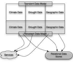
Persistent Data Model ... 40
Transient Data Model ... 45
Drought Data Model ... 56
Persistent Data Model ... 57
Transient Data Model ... 62
Geographic Data Model ... 66
Persistent Data Model ... 66
Transient Data Model ... 70
Connector Architecture... 71
Chapter 5: Framework Component Model ... 73
Climate Components ... 75
Native Components ... 87
Geographic Components ... 88
A Framework Architecture ... 92
Chapter 6: Case Study – Two Decision Support Systems ... 94
The GreenLeaf Project: A reference implementation ... 95
The National Agricultural Decision Support System: An extension ... 97
Component Decoupling ... 100
Data Connectors... 102
Model Decoupling ... 104
Developer Support ... 105
Conclusion ... 107
Chapter 7: Contribution and Future Work ... 109
Future Work ... 109
Bibliography ... 111
Appendix A ... 113
A1 – Sample FIRM Client Program ... 113
LIST OF FIGURES
Figure 1: The 3Co framework architecture 7
Figure 2: An implementing architecture 14
Figure 3: Dynamic MBean class structure 17
Figure 4: Manager / Accessor design pattern 18
Figure 5: Example ServiceImpl class 20
Figure 6: Property accessor sequence 22
Figure 7: Example use of the DataSourceInjector and Logger services 25
Figure 8: GIS component class relationships 28
Figure 9: NCC deployment architecture 33
Figure 10: The FIRM data model 39
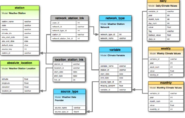
Figure 11: Persistent climate data model relationships 40
Figure 12: A CalendarDataCollection iteration example 47
Figure 13: Example FIRM output 47
Figure 14: Example data summation code 53
Figure 15: Example metadata iteration code 54
Figure 16: Example FIRM output 55
Figure 17: Persistent drought data model relationships 58
Figure 18: Example drought report iteration code 65
Figure 19: Example FIRM output 65
Figure 20: Persistent geographic data model relationships 67
Figure 21: The FIRM component model 73
Figure 22: The structure of a native component 87
Figure 23: FIRM application model diagram 95
LIST OF TABLES
Table 1: Description of the station table 41
Table 2: Description of the absolute_location_table 42
Table 3: Description of the station_location_link table 42
Table 4: Description of the network_type table 43
Table 5: Description of the source_type table 43
Table 6: Description of the network_station_link table 43
Table 7: Description of the variable table 43
Table 8: Description of the daily table 44
Table 9: Description of the weekly table 44
Table 10: Description of the monthly table 45
Table 11: Description of the media_reports table 59
Table 12: Description of the user_reports table 60
Table 13: Description of the impact_reports table 60
Table 14: Description of the media_impact_link table 61
Table 15: Description of the user_impact_link table 61
Table 16: Description of the report_category table 62
Table 17: Description of the counties table 68
Table 18: Description of the cities table 68
Table 19: Description of the zip_code table 68
Table 20: Description of the spatial_reference table 69
Table 21: Description of the spatial_regions table 69
Table 22: Description of the reference_zip_code_link table 70
Table 23: Description of the reference_city_link table 70
Table 24: Description of the reference_county_link table 70
Table 26: The ClimateMetaDataQuery component definition 77
Table 27: The DroughtIndexQuery component definition 80
Table 28: The DroughtImpactQuery component definition 83
Table 29: The DroughtImpactManager component definition 86
Table 30: The SpatialQuery component definition 89
CHAPTER 1: INTRODUCTION
MOTIVATIONThe growth of Internet applications used for everyday activity has resulted in an increase in demand for high-availability data systems in research and decision support communities. This demand is being met by the development of vast data repositories and applications that provide users with information from current stock quotes to what friends are planning over the weekend. These data are increasingly being used to make decisions and take actions. Whether recognized as such, many of the web applications that people are interacting with every day could be considered to be decision support systems. The increased awareness of data-driven web applications combined with their integration into new decision workflows results in the greater availability of data to support decision-making activities. Additionally, a new class of information worker emerges who is proficient in isolating data necessary to more effectively make decisions.
A traditional decision support system is defined as an information system that "draws on transaction processing systems and interacts with other parts of the overall information system to support the decision-making activities of managers and knowledge workers in [an] organization" [1]. The workflows encapsulated by traditional decision support systems typically revolve around a user feeding parameters into the system, the system computing some result based on the parameters, and the results being presented in a usable format. In this type of decision support system, workflows encapsulate domain processes based on the user classification. One of the more frequent uses of this approach is user partitioning in software wizards; screens for Novice, Intermediate, and Advanced users are separated into unique workflows from the same set source of data [1,2,3,4]. In this approach, each wizard incorporates differing levels of functionality leading to a similar result.
With the rise of web-based applications and the broader availability of data through the Internet, decision support began to incorporate aspects of knowledge management. Static workflows gave way to dynamic information discovery based on many sources of data. In this model, data are partitioned based on their relationship to other data and are frequently fed through domain-centric models or workflows to
create information. In these systems data and information can also be combined to create higher-order data that are termed knowledge [4]. The data segmentation that has grown out of the introduction of knowledge management principles has resulted in a significant focus being placed on domain models and workflows as well as the acquisition of domain specific data sets. Where decision support systems were previously driven by user controlled models and workflows, they are now largely being driven by availability of domain-relevant datasets. User interactions with these systems require less focus to be placed on the type of user and more on the kind of information that is needed. Domain models and workflows become transparent to the overall tasks of data, information, and knowledge discovery. The architectural constraints that are placed on what one can term a Data-Driven decision support systems pose a number of new challenges to system development. These challenges arise principally from the role of data integration in system development.
With a focus on the availability of data to form information and knowledge, a Data-Driven decision support system must be able to quickly integrate high volumes of unrelated data in order to remain relevant. The availability of remote datasets accessed through platform independent protocols must be easily leveraged by data-driven systems to provide detailed views and assessments within the considered domain. This availability requirement poses a significant data integration challenge to software developers creating such data-driven systems. Datasets can be as varied as the data themselves, coming from static data repositories, network aware devices and sensors, or other applications through web services. Web applications and services are becoming increasingly location-aware, further complicating the data integration process by amassing large quantities of GIS data. This creates an orthogonal data format to be integrated in the system. These GIS data repositories can easily grow to multiple terabytes in size and are frequently delivered through geo-spatial web services external to the system. With much of the data being external to the system, highly adaptive software must be created to facilitate the integration and availability of data.
A second challenge arises when one considers the domain specific models and workflows encapsulated by decision support systems. While generally transparent to the decision support activity, these models and workflows are required to create information and knowledge. The results of one
process can become an internal dataset required by another process to create information or build knowledge and thereby portray an accurate view of some domain state. External data can be integrated to form an internal dataset supporting processes or published as a dataset to be consumed by other systems. This requirement results in the abstract view of a decision support system being composed of many connected paths passing through data integration points. At any given point, another dataset can intersect the current path, requiring that the data be normalized in some way to allow integration to take place. In the context of the software design, this problem can be easily addressed by creating a normalized central dataset to support system processes. However, when considered in relation to the evolving data landscape of the Internet, size of data sets, and the need to have current results, static normalization of the data is often not an option.
Data normalization can, however, be accomplished in software through the application of Component-Oriented (CO) design principles [5,6,9,22]. By encapsulating dataset operations into independent software components, processes interact with the dataset through software components rather than directly. These software components give system developers a finer level of control overdatasets that are disparately consumed and uniformly reproduced within the system. System operations are partitioned into groups based on the data operations they wrap. This highly cohesive and loosely coupled implementation pattern is a hallmark of Object-Oriented (OO) system design, and can be very effectively extended to support data-driven software development [6,10,23].
The primary goals of CO architecture are to address data flow between components and create an infrastructure upon which to build use case conformant software [5,6,22,23]. In the context of decision support systems, data integration requirements result in a loose view of date flow between components. The architecture is less concerned with which components data may pass through and is more concerned with how data passes in and out of the component. In order to realize this black box view of component data flow, the architecture must enforce a strict data model. Logic for accessing an individual dataset or executing some domain specific process or workflow is isolated in unique components. Data integration is accomplished through runtime composition of component calls.
APPROACH
While this architectural view of a data-driven decision support system aligns with the unique challenges presented by data integration, it fails to address the resulting component integration problems that would arise from its implementation. Distribution and configuration of components around a unified application model is needed to support application development in this paradigm. To address this problem, this thesis proposes the implementation of a Service Oriented Architecture (SOA),which integrates middleware services with the component model described above. The SOA is realized through the implementation of a set of core foundation services consisting of the following elements:
1. A centralized management framework.
In a SOA, components can be distributed across multiple applications and systems. In order to coordinate communication between components and determine the availability of a component to process a request, a centralized controller is required. The centralized management framework is introduced to act as a controller for all component invocations. The centralized management framework is based on a design pattern for partitioning component management operations and lookup services. Through the use of the Manager/Accessor design pattern, component interactions are loosely coupled with centralized management framework operations. The centralized management framework creates abstract groupings of components around common configuration needs such as shared data source or domain workflows.
2. Core integration services API
Supporting the high-level configuration and discovery services provided by the centralized management framework is a set of service APIs for managing component interaction with the framework. Common crosscutting services like access control, logging, notification, data source connectivity, and domain data model operations are made available to components through the core integration services. The core integration services support the black box composition of components within the framework and represents a bridge between framework functionality and middleware services like connection pooling and load balancing. The core integration
services also facilitate data sharing through the publication of services backed by component implementations.
3. An integration component runtime.
An implementation of private core integration services API classes is made available to applications through the integrated component runtime. The integrated component runtime manages communication between framework components or consumer applications and the centralized management framework. The integrated component runtime allows these framework communication classes to remain private while at the same time being available to callers to manage centralized management framework connections and component call marshalling. The integrated component runtime provides the runtime context for all components both internal and external to the framework.
The proposed framework implementation is built using several key Java technologies including: Java Enterprise Edition (Java EE) 1.5 [8], Java Management Extensions [7], and Java Persistence Architecture [11]. The framework takes advantage of many of the service and component oriented constructs made available by these technologies. Additionally, the Java EE specification provides a number of middleware services that are available to the framework to support required deployment and runtime operations. While Java technology provides a platform upon which to implement the proposed architecture, the key concepts presented here are not unique to Java; this architecture could be implemented with other component-based development platforms.
OUTLINE
The remainder of this thesis is structured as follows. Chapter 2 presents background and related work. Chapter 3 presents the formal architectural specification for a service-oriented decision support framework, discussing framework configuration, service providers, and application middleware and deployment considerations. The Framework for Integrated Risk Management is introduced as a reference implementation framework to support application development in the agricultural decision support domain; Chapters 4 and 5 focus on elements of this framework. Chapter 4 introduces the domain model
for The Framework for Integrated Risk Management, discussing various aspects of the model and their support function for a component model. Chapter 5 presents the component model and discusses how it is used to support development of application software. Chapter 6 presents a case study of two decision support systems that used the framework, and Chapter 7 concludes with contributions and a discussion of future work.
CHAPTER 2: BACKGROUND AND RELATED WORK
This chapter discusses the framework that is a predecessor to this work and drove to the approach described by this thesis. In addition to the legacy framework, several key technologies that emerged at the outset of this work are discussed. Some of these technologies were used in the development described later and others were used as the basis for conceptualizing several architectural patterns and methodologies that were later adopted by the framework presented by this thesis.
THE 3CO FRAMEWORK
The 3Co framework was a framework developed to support the design and implementation of components and component connectors to facilitate data integration. The framework focused on the design of the components and connectors, as well as the coordination of components by runtime callers [4+. These aspects, the three ‘cos’ of the framework, were used as the basis for the development of decision support systems in the agricultural domain. The resulting decision support, The National Agricultural Decision Support System, provided a basis for evaluation of the 3Co framework and had significant influence on the work presented here. 3Co and NADSS and the issues that arose with integration of new datasets during development of the systems were the driving factors in the design of the architecture presented by this thesis.
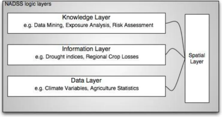
The 3Co architecture was a layered architecture, grouping components into one of four classifications based on the data they would provide.
The high-level architectural view of 3Co is depicted in Figure 1. This hierarchical layered view of the framework was realized by the classification of components as data, information or knowledge components. Lower level components were used by higher-level components to generate data as defined by the layer. Information layer components, for example, computed data values based on the application of models to data layer component data. Knowledge components, in turn, used information and data for computing values. The framework included an orthogonal spatial layer [12] that, through connector definitions, allowed values from each of the three other layers to be rendered spatially.
3Co provided a basis for the development of decision support tools and supported the development of tools around connectors. Discussed extensively in Chapter 6, 3Co was achieved success at developing decision support systems in a distributed environment. It was, however, the static connector definitions that presented the largest obstacle to data integration within the framework. The challenges to integrate data using the framework led to the consideration of a more agile and dynamic architectural methodology to overcome data integration obstacles. The use of SOA as a basis for that design was motivated by the more monolithic layered approach taken by 3Co. The proposed architecture builds off many 3Co concepts of component orientation, generation of data through component connection, and use of connectors for application modeling. These concepts are enhanced in several ways by the availability of new technology and design styles discussed throughout this chapter.
SERVICE ORIENTED ARCHITECTURE
Service Oriented Architecture (SOA) is a way of composing an application through the consumption of disparate component functionality delivered through a common network-aware interface, a service. These applications aggregate many different data sources in what is commonly termed a mash-up in order to provide their functionality. SOA builds on distributed system concepts that have existed for many years [5,6,10]. The main difference is that SOA requires design parameters aimed at simplifying many application integration challenges commonly associated with distributed system implementation [10]. A SOA is composed of many services exposing operations mapping to application use cases. A service has the following key properties [10]:
Platform Independence – The interface definition exposed by a service does not contain any platform specific assertions or parameterization. This property gives rise to the use of XML-based messaging over HTTP-based protocols for operation invocation. This property can be considered one of the key components to the tacit linking of web services and SOA.
Dynamic Service Discovery and Linking – Services register themselves in some way at runtime allowing consumers of the service to bind to and invoke operations at runtime. This dynamic binding is generally facilitated through a remote protocol such as IIOP or HTTP. This attribute requires that services can be invoked.
Service Autonomy – Services exist independent of each other, internalizing all operations and state. Other services can interact with the service through the well-defined contract only. All other information about a service is hidden.
These properties allow SOA applications to easily integrate application functionality provided by other components or remote applications. The ease of integration, paired with the increased use of the World Wide Web for application delivery, is resulting in the emergence of SOA as the de-facto standard for Internet application development.
From the standpoint of data integration, the concept of application integration poses several potential uses. The elements of platform independence, linking, and autonomy can all be used to support abstraction of elements in a component architecture for the integration of data as a service. The architectural model also supports significant decoupling between its components, allowing for flexibility in the design and implementation of architectural support elements. These aspects of SOA make it appealing as a basis for a framework for data integration.
JAVA EE 5
The Java Platform Enterprise Edition (Java EE) defines a standard architecture for developing applications that “combine existing enterprise information systems (EISs) with new business functions that deliver services to users” *8]. The Java EE specification, developed as JSR 244 in 2005 and 2006, introduced significant improvements over J2EE. These improvements dealt primarily with the abstraction
of the underlying framework from components being developed in it. The goal of the these improvements centered around the use of plain old Java objects (POJOs) to be able to act as enterprise Java beans (EJBs) with no more than annotations. EJBs, or the Java EE definition of a component, could be easily constructed to incorporate only elements of the computational functionality required to implement the needed business logic. Architecture services, like transaction and persistence, were also incorporated into the component implementation through the use of annotations and deployment injection. Functionality was incorporated into a component as it was deployed to a middleware runtime, not as it was developed or packaged during development.
The updates made with the Java EE specification not only make the platform an appealing choice for the development of a framework for data integration, many of the elements of abstraction found in the specification motivate the implementation strategy for such a framework. Component isolation through middleware service injection can be used to provide significant decoupling between components and framework services while maintaining service functionality. This design consideration, a hallmark of object and component oriented design, is an important aspect of the proposed method for data integration. Java and Java EE can also be used as the overall runtime platform for the proposed framework, allowing the framework to be designed and implemented independently while at the same time incorporating several robust services in deployment.
JBOSS APPLICATION SERVER AND FRAMEWORKS
The use of JSR 244 elements in the design and implementation of the architecture presented in this work were heavily influenced by the JBoss implementation of the specification. JBoss approached the concept of service injection in EJB components through the application of aspect oriented programming (AOP) [25], developing a weaving compiler to introduce service functionality to components. The use of AOP as a basis for the separation of concerns within the framework motivated the development of a set of integration services discussed later. The use of AOP was initially considered and then abandoned due to overhead associated with development. Many of the AOP concepts, however, can be seen in the use of proxy services and general structure of services discussed later.
JBoss also introduced the concept of the use of the Java Management Extension framework to create deployable service components to support runtime configuration as well as EJB extensions to create component connections [24]. The extended deployment structure was adapted to form the basis for the later discussed centralized management framework. The deployment structure of the service components was altered slightly to allow deployment external to the framework application, however the annotation set used mimicked the JBoss implementation with only minor additions needed throughout development.
The design patterns used by JBoss in early implementations of a JSR 244 compliant application server had the greatest influence on the design of the framework for data integration. While 3Co motivated the solution to the problem, JBoss motivated the implementation of the solution in its use of existing Java technologies to accomplish a number of service abstractions in support of deployed application component models. Both of these factors, combined with the rich framework development environment provided by Java EE were all incorporated in the development of a service oriented architecture for data integration.
CHAPTER 3: FRAMEWORK ARCHITECTURE
Service Oriented Architectures (SOAs) are component-oriented systems that publish component business logic for consumption by other systems [10]. The central building blocks in these systems are the components, which encapsulate some domain-specific functionality. Components are designed to be black box computational units, which work together to comprise the complete application functionality. In the Java EE specification this black box structure is accomplished by providing a component interface and implementation. An EJB container in application middleware manages the component instances, called Enterprise Java Beans (EJBs); generally this is done using the Java Naming Directory Interface (JNDI). Callers use the component interface to interact with component instances through proxies created by the JNDI context. These proxies can be remote or local. Proxies to remote components use protocols like IIOP, CORBA, or JNP to invoke methods on the component instances and can be deployed across JVMs; local components restrict calls to the same JVM instance in which the proxy is running. The underlying object instance created by the JNDI context is hidden from the callers through the component interface, allowing transparent component co-location and facilitating system distribution.
With this view of the component model, one can conceive of a component framework tied together with services to support unification of data flows between components. By implementing a framework architecture, component implementations are easily integrated by building them against the common service structure and services can be easily created against common component elements. The framework architecture presented here is made up of three abstract elements, the centralized management framework, The core integration services and the integrated component runtime. These elements together form the core foundation services. Each core foundation services service works separately to collectively constitute an environment in which components can be deployed and interaction with other components facilitated. This high-level view of the framework architecture represents an abstract specification for the framework itself, omitting the component and data model implementations. Implementations of this architecture provide data and component models, integrated
with each of the Core Foundation Services. This abstraction is chosen primarily to allow application of the architecture within multiple decision domains. Decision support systems span many varying domains making the abstraction of an efficacious cross-domain application or component model difficult. By providing architectural elements to facilitate loose communication between components through a well-defined, domain-centric data model, wider adoption of the architecture for decision support system development is supported.
The goal of the framework architecture is to isolate domain processes, models, and data repositories by encapsulating interactions with these elements in component invocations. This component-oriented architectural organization of framework logic facilitates the inclusion of new data and domain methods with little impact to the overall system. Only those components making use of new additions need to be modified, and then only if the inclusion impacts the data model. In well-defined application domains a data model will infrequently require change, providing near transparent inclusion of components in the implementing system. A secondary goal of the architecture is to create an environment where consumers of component data, information or knowledge can transparently interact with the framework. Component bindings are externalized to support both internal system operations and external systems. Due to the isolation of component and data access logic, the bindings can be integrated with systems maintaining orthogonal data models. Model definitions are encapsulated in a static object model, allowing component binding to take place without impact to the consuming component or system.
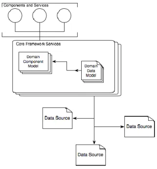
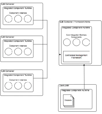
These architectural goals are accomplished by integrating the implementing component and data models with the services offered by the core foundation services. The framework is designed to create an environment in which supporting services are abstracted from the component and data models to support greater integration flexibility. This abstraction allows the implementation to focus on the domain modeling rather than framework development; service delivery and integration support are accomplished through interaction with the core foundation services. The architecture is implemented by integrating domain-centric component and data models with the services provided by the core foundation services, resulting in the following view of an implementing architecture.
Figure 2: An Implementing architecture
In this view, the component and data models are wrapped by the core foundation services to create component implementations and facilitate access to external data repositories. The following issues are addressed by the Core Foundation Services.
1. Shared configuration. Components require configuration parameters at runtime to determine data source and service connection information, internal state, and runtime behavior. In many cases these configuration elements can be stored as property files or in databases. Traditional configuration mechanisms do not address the need for shared configuration between common components that are not deployed together. In a distributed component deployment, where multiple components may be abstractly linked through a common configuration, it is imperative that all components participating in a data workflow share configuration state. This can be accomplished in the framework by providing a common configuration factory using Java Management Extensions (JMX). Distributed components can be notified through Managed Bean bindings of parameter changes at runtime, preventing synchronization issues across components. The framework can also utilize shared configuration services in order to determine the availability of components to fulfill requests.
2. Middleware integration. The Java Enterprise Edition specification provides a number a number of middleware services for components to take advantage of at runtime. Middleware services can be used to provide common data source and service connectivity, framework monitoring, security, transaction management, and persistence [8,11]. While application servers provide entry points to service APIs, it is important that framework components consume these services in a uniform way to ensure common component operation. Shared configuration can also be thought of as a middleware service and may be utilized by components to determine how services are consumed. For this reason it is necessary for the framework to provide a component bridge for accessing shared functionality.
3. Runtime integration. In order to achieve a loosely couple component architecture it is necessary for abstract component bindings to be realized dynamically at runtime. A component runtime can be provided that will supply dynamic component bindings at the point of invocation. This allows for a greater level of distribution in the architecture. Runtime integration is also required to provide service bindings to shared configuration and middleware services, isolating component implementations from framework logic. The runtime is responsible for determining component availability and provides a bridge to clients communicating with framework components.
The core foundation services addresses each of these issues by providing managed services to framework components. The following is a discussion of each of these services and their impact on the component and data models.
CENTRALIZED MANAGEMENT FRAMEWORK
The centralized management framework provides shared configuration for framework components. The centralized management framework utilizes Java Management Extensions (JMX) to deliver configuration and management functionality to components and to the framework itself. Examples of management functionality can include the path to JNDI instances, external data source bindings, log verbosity, or runtime instrumentation. The centralized management framework is
composed of a Managed Bean (MBean) server wrapper and a set of objects conforming to a framework design pattern called the Manager / Accessor Pattern. The MBean server can be created as a standalone server or can utilize middleware MBean servers as discussed below. The centralized management framework wraps the MBean server by providing a deployment interface for the runtime creation of MBeans from properly annotated Java objects. This allows framework developers to express configuration elements as part of the data model rather than constraining elements to a JMX-centric view of the architecture. MBeans, known to the centralized management framework as services, are used as service objects because they are decoupled from the configuration architecture and can include crosscutting framework functionality.
The Java Management Extensions (JMX) specification defines an architecture for monitoring and configuring Java objects at runtime [7]. The JMX architecture provides several levels for deploying, managing, and connecting to instrumented resources. The centralized management framework utilizes the Instrumentation Level of the JMX architecture to publish services as managed resources. Resources are made manageable (i.e. services are created) through the JMX Agent Level by implementing MBeans, which are deployed to an MBean server. This Instrumentation Level pattern decouples the MBean from the JMX implementation and allows any system class to be easily refactored into an MBean. Decoupling is important in that it allows the inclusion of framework specific functionality like service persistence. The Instrumentation Level also provides a notification framework to facilitate the propagation of notification events between MBeans.
The JMX specification defines two classes of MBean, standard and dynamic. Standard MBeans are Java objects having an explicitly defined management interface. The management interface defines the methods made available for invoking operations on the bean or reading and writing its properties, and must conform to the Java Bean design pattern [13]. Standard MBeans expose managed attributes and operations statically through the management interface and cannot be modified to expose additional operations at runtime. The second type of MBean, the Dynamic MBean, exposes attributes and operations dynamically at runtime by implementing a method which returns all operation and attribute signatures. The JMX specification includes theDynamicMBean interface that a Java object can implement
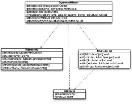
to be considered a Dynamic MBean. The interface specifies abstract methods for obtaining attribute values or invoking operations. The following class diagram depicts a Dynamic MBean class.
Figure 3: Dynamic MBean class structure
Classes implementing the DynamicMBean interface must implement the logic to determine MBean attributes, values, and operations at runtime based on parameter values. Attributes and their values can come from XML documents, databases or other classes and the sources for attributes or their values can be changed at runtime. Likewise, operation logic can be determined at runtime from multiple sources or can be configured to different behaviors under specific system states. Dynamic MBeans offer greater flexibility as management information can be updated, after the MBean has been deployed, in response to state changes within the framework.
The centralized management framework uses the JMX specification to create instrumented resources for management of components. These resources are deployed by the centralized management framework as services to be consumed by framework components. Because the centralized management framework provides its own service persistence logic and access control, services are realized through the implementation of Dynamic MBeans; the ability to create an abstract service infrastructure built using JMX was a key driver in this decision. Services are identified by the centralized management framework through the use of annotated classes following the Manager / Accessor design
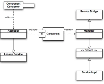
pattern. The Manager / Accessor design pattern was created to allow some configuration elements to be made available to caller components while making others available to only the binding component. The pattern is so named as it specifies two access objects for the component configuration, the Manager and Accessor. The following diagram shows the class relationship that is required by the design pattern.
Figure 4: Manager / Assessor design pattern
In this design pattern, configuration is provided to a component through the Manager. The Manager allows access to properties and operations that are to be made available to a component. Generally these would include externalized properties and crosscutting operations. The Accessor in turn allows access to operations that a component caller would utilize in order to access the component and exposes no configuration properties.
The Manager and Accessor are supported by two centralized management framework delegates by extending an abstract base class providing delegate functionality. Each delegate provides the abstract functionality needed by the extending object to service component requests. In the case of the Accessor, the LookupService delivers service location functionality following the Service Locator design pattern [6]. The LookupService is used to locate components by class name from the appropriate JNDI instance based on connection information provided by centralized management framework Services. This delegate utilizes core integration services and integrated component runtime elements, discussed later, to provide component bindings and determine connection parameters. Each Accessor extends the LookupService,
creating a new delegate instance for each Accessor instance. The lookup logic is abstracted and encapsulated in the LookupService and each component Accessor must pass the fully qualified component interface class name to obtain a reference to a specific component. The LookupService maintains a reference to a JNDI context defined in a configuration service and injected by the integrated component runtime that is used to obtain remote component instances. This abstraction creates a single point of lookup within the framework, which supports many component accessors and creates a common integration point for binding to other CSF services. The Manager participates in a considerably more complex set of interactions than the Accessor in that it provides proxy access to services through Dynamic MBeans rather than relying on a single delegate implementation.
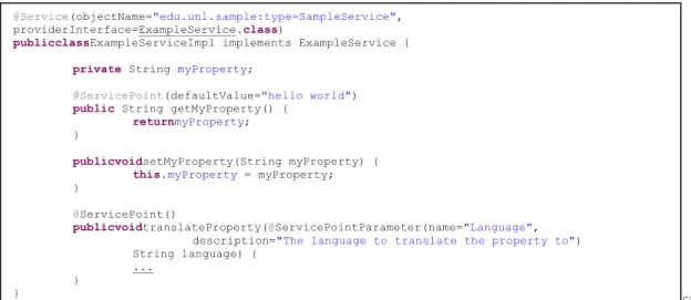
A centralized management framework service is essentially a registered Dynamic MBean wrapped by persistence logic provided by the centralized management framework and created from an annotated class known as a ServiceImpl. A ServiceImpl is a Java object annotated as a Service whose property reader and operation methods are annotated as a ServicePoint. The Service annotation requires that an object name be provided for use by the centralized management framework to identify the MBean that is created in the JXM Agent Level. TheServicePoint annotation allows for a default value to be specified in the case of a property access method. Each annotation also allows a meta-data description to be provided. Method parameters can optionally be annotated as ServicePointParameters in order to provide additional meta-data to the method by describing parameter function; the meta-data are encapsulated into an MBeanInfo object at the time the MBean is created. These annotations are used by the centralized management framework in the deployment of services to determine which operations and annotations to expose in the MBean.The following is an example of an annotated ServiceImpl class.
Figure Figure 5: Example ServiceImpl class
In the example, the ExampleServiceImpl is a Java class which implements the ExampleService interface. This interface represents the management interface through which other components will access the service functionality. The class is annotated as a Service and both an object name and the service interface are specified. Despite implementing the ExampleService interface, the deployer will use the actual annotation to determine how the MBean will be created, so the interface must be specified there; this is known as the providerInterface. The use of interface inheritance is only a function of good OO-style and could be omitted entirely as the methods’ invocations will be preformed dynamically at runtime with the MBean implementation. The example class provides three methods, two of expose the myProperty property. These follow the Java Bean convention for property access, and the getter is annotated to expose the property in the MBean. The setter could optionally be omitted and would result in myProperty being read-only in the MBean instance. The third method is also annotated as a ServicePoint and would map to an MBean operation. The parameters of this method are documented with ServicePointParameter annotations.
The centralized management framework contains a deployment framework responsible for the management of services through the creation of MBeans from ServiceImpl classes or instances. The ServiceDeployer is the centralized management framework object responsible for creating and managing the services. The ServiceDeployer maintains a reference to an MBean Server where the created MBeans will be deployed. At the startup of the framework the ServiceDeployer will either create an MBean Server
@Service(objectName="edu.unl.sample:type=SampleService", providerInterface=ExampleService.class)
publicclassExampleServiceImpl implements ExampleService { private String myProperty;
@ServicePoint(defaultValue="hello world") public String getMyProperty() {
returnmyProperty; }
publicvoidsetMyProperty(String myProperty) { this.myProperty = myProperty; }
@ServicePoint()
publicvoidtranslateProperty(@ServicePointParameter(name="Language", description="The language to translate the property to") String language) {
... }
associated with its instance or bind to a container managed server. An environment property is set to determine how the MBean Server is obtained. Generally, if the framework is deployed in an existing application server, the container provided MBean Server is preferred; this is the default behavior. The ServiceDeployer creates a new service from a provided ServiceImpl by instantiating a new ServiceBase object with an instance of the ServiceImp and deploying it to the MBean Server.
A ServiceBase is a Java object implementing the DynamicMBean interface as required by the JMX implementation. The ServiceBase maintains internal lists of exposed getter, setter and operation methods by evaluating the annotations on the provided ServiceImpl class through reflection. Each access or invocation type is maintained in a separate list, one for getter methods, one for setter methods, and one for operations. Methods without ServicePoint annotations are omitted from the method lists. When the ServiceDeployer encounters an annotated getter method, it looks for a corresponding JavaBean setter method for that property. If one is found, that method is added to the setter list and the property is considered read/write. If not found, only the getter is added to the method list and invocations attempting to set the value of the property will fail, resulting in read only access to the property. The internal method lists are used by the DynamicMBean methods to provide attribute values and operation invocations and allows the single type of ServiceBase to provide functionality for any number of services, each differentiated by the underlying ServiceImpl instance. This structure enforces decoupling of the centralized management framework services from the JMX implementation in that the JXM implementation is only directly referenced by the ServiceBase and could be replaced at a later time by another management architecture with no change to the centralized management framework service implementations.
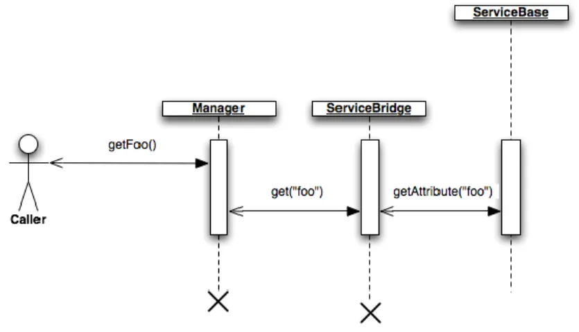
Service functionality is exposed to framework components through a Manager associated with the service through the provider interface. Much as the Accessor provides component lookup functionality, the Manager exposes service operation and attribute values statically by implementing the service provider interface. The actual MBean attributes and values that the Manager wraps are invoked using standard MBean access logic encapsulated in the abstract class ServiceBridge, which the Manager extends. When constructed, the Manager invokes its super class constructor, passing in the MBean
object name used when the ServiceBase was registered with the MBean Server. The ServiceBridge then binds to the MBean and maintains an abstract MBean object reference for Manager operations to be invoked against. In this way, a Manager class method implementations call super methods on the ServiceBridge to access the backing MBean to return values to the caller. Caller classes could bind to the MBean directly, removing the need for the Manager, however this would decrease type safety and expose the underlying JMX implementation to callers.
The implementation of the Manager has the potential to create a significant security flaw in the framework. In order for the ServiceBridge to invoke Manager operations it must have access to the underlying MBean server. MBean server invocations need not be limited to only those named MBeans that the framework manages; when using the container MBean server, the ServiceBridge has access to all MBeans, including those which manage the container itself. To address the potential security exploits that could be created by call interception, the pattern expressly requires that server-side classes only extend the ServiceBridge. This prevents client code from having direct access to the MBean server. A further guard is introduced by using the JMX security model to ensure that only authenticated callers are allowed to invoke MBean operations. Authentication functionality is injected into the ServiceBridge by the integrated component runtime runtime context discussed below. The following sequence diagram illustrates an attribute access operation through the manager.
By using JMX as the underlying configuration infrastructure, the centralized management framework can expose configuration attributes and operations to external management applications; most notably the middleware management console for the application server hosting the framework. This results in greater application deployment flexibility as the framework can easily integrate with existing deployment management solutions so long as they support JMX. This implementation allows the component configuration to be modified at any time in response to events like loss of connectivity or by a deployment manager for maintenance or redeployment. The design of the centralized management framework is such that is allows the framework to be easily adapted to changing deployment conditions with minimized loss of functionality of the framework components.
CORE INTEGRATION SERVICES
Where the centralized management framework encapsulates configuration logic and distributes it to collections of components, the core integration services are framework specific components and classes designed to support the implementation component model. Core integration services components and classes provide component model implementations with framework functionality that crosscut the domain model. The core integration services are designed to avoid redundant implementation and normalize framework operations. Core integration services components and classes support the component model implementation and integrate with other core integration services, data repositories, classes and centralized management framework functionality; it can be thought of as a base component model. The logic encapsulated by these components and classes are designed to cross cut domain specific implementations and are provided to facilitate greater reuse and standardization among component model implementations. The core integration services act to provide middleware functionality to the framework components, exposing functionality of the deployment containers to components in a framework specific way. This isolation of components from direct container interaction results in a more portable framework. As long as the core integration services are implemented to specification in a Java EE compliant container, framework components can be deployed into that environment.
The core integration services are a collection of components and classes, interacting with the framework in the same way as component model implementations. Foundation services are provided to component model implementations through the same service model used to integrate components. This allows the extension of the framework with new service functionality to take place without modification to existing component implementations; it achieves the black-box goal of the framework internally. Service implementations in the core integration services can take two forms: direct invocation or proxy. Direct invocation services are those that are statically bound to component implementations (i.e. the component class maintains a reference to an object instance providing the service). Proxy services wrap component invocations to extend the functionality of the component in a uniform way and can alter the flow control of the component invocation.
Direct invocation services are generally responsible for delivering integration points to middleware services, wrapping that functionality in a framework specific way. The core integration services include a direct invocation service called the DataSourceInjector. This service encapsulates the logic to perform a JNDI lookup on a JDBC data source created by the middleware container. The DataSourceInjector provides a uniform way to bind components to JDBC data sources. The static class is supported by a DataSourceType enumeration that contains a list of system data sources. The use of an enumeration is designed to make refactoring application code easier as a single update can change all references to a specific data source type. The data source types can be bound to JNDI data sources in the centralized management framework, allowing data sources to be dynamically swapped out at runtime. The DataSourceInjector can optionally use a string argument representing the JND name, bypassing the static enumeration.
A second direct invocation service commonly used across component implementations is the Logger. The Logger provides uniform logging services to components and classes and can integrate with a JDBC resource, external file, or container managed logging services to log statements are runtime. The Logger is bound to centralized management framework services to allow control of statement logging at runtime. Statements passed to the Logger are bound to the classes from which they were issued, allowing for better processing of log information. The Logger provides four loggers, partitioned around
the functionality encapsulated by the object logging statements. These loggers include a component, service, system, and application log to control how logging information is stored and allowing different framework functionality to be logged at different levels. Log levels are used to indicate the type of statement being logged and are used when setting logger verbosity. Statements are logged as either fatal, error, warn, info, or debug. These levels can be set separately for each logger, allowing, for example, all services to log fatal errors only, while components log debug information. The design goal of the Logger is to allow the system to be adjusted at runtime as needed to isolate faults or determine infrastructure needs. The following is an example of a component using the DateSourceInjector and Logger services.
Figure 7: Example use of DataSourceInjector and Logger services
In addition to middleware service wrappers, the core integration services provide several components that wrap external functionality in a framework-centric way. One such service included in the core integration services is a search engine that integrates with the data model implementation and acts as a direct invocation service. The SearchService provides full text fuzzy search logic by indexing objects implemented as part of the data model, building on object persistence logic provided by the Java Persistence Architecture (JPA). Objects that are to be indexed and queried through the SearchService must be JPA annotated Java objects. The SearchService requires that, in addition to JPA annotations, a set of search annotations be included as well. These annotations are used by the SearchService when
publicclassSampleComponent {
privateDataSourcesource =
DataSourceInjector.injectDataSource(DataSourceTypes.SYSTEM);
privatestatic Logger LOG = Logger.getLogger(Loggers.COMPONENT_LOG,
SampleComponent.class);
publicvoidclearUsageData() { Connection conn = null; try {
conn = source.getConnection(); } catch ( Exception e ) {
LOG.error("could not obtain a connection", e);
LOG.debug("Total memory: "+Runtime.getRuntime().totalMemory()); }
... }
generating indices to identify searchable objects, properties exposed for search, search result description, search result identifier, search result name, and search result meta data. The latter five annotations are used by the SearchService to build search result objects that will be returned when a search operation is invoked. These search result objects are proxies for the actual Java objects, exposing only those annotated values to maintain smaller search result sets. The actual object can be loaded from each search result to provide all data encapsulated by the object. Objects are loaded and indexed by the SearchService using reflection to determine searchable properties and result values. The SearchService integrates with the centralized management framework to expose management operations for building a new search index.
Apache Lucene2 provides actual search logic; the SearchService is a black-box wrapper for this functionality, which could be replaced without impact by another search provider. The main goal of the SearchService and its annotations is to wrap the functionality of the implementation search engine to abstract it away from caller components. This would allow for other search engine implementations to be substituted after implementation with no impact to the component or domain models. The operations and annotations provided by the SearchService are generic enough to facilitate search operations without need for implementation specific data to be incorporated into the domain model, decoupling the search implementation from the data model. This decoupling is further reinforced through the use of a generic search result object. The SearchResult object includes methods for generically obtaining search result information based on meta-data included in data model objects. The basic elements of a search result are the result title, text or description, and any additional named meta-data. Each SearchResult maintains the lookup parameters of the data model object mapping to the result, allowing for object to be loaded as needed. The primary driver for the encapsulated search data is to increase performance of result rendering by clients.
The core integration services also include a bridge to GIS services for accessing, manipulating, and publishing spatial data. The GIS service bridge is included to give framework components direct
2
access to spatial data. Unlike standard relational databases, which can be referenced through middleware services provided by the application container, spatial operations require either custom implementation or integration with external services. The spatial operation components included with the core integration services are backed by commercial GIS packages from ESRI and include ArcGIS Server, ArcObjects, and ArcSDE. The integration of these products as components in the framework is based off work in [12]. The premise behind the GIS services is that framework components may need to consume or produce spatial data and that production or consumption of the data should happen in a framework-centric way. Due to the complex nature of GIS service components, transparent integration with external services is far more practical than development of internal components to manage GIS operations. By utilizing an external service, GIS data produced by the framework and can be easily published and shared with other systems in a standard way. The abstraction also allows for the external GIS service to be replaced as needed with little impact on the framework components utilizing its functionality.
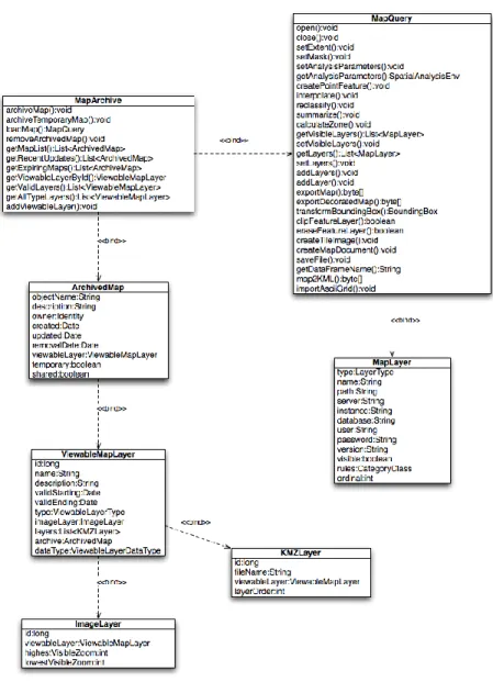
Framework components access GIS functionality through two components, the MapQuery and MapArchive. Several classes designed to implement an abstract spatial data model support these spatial components. Generally, the implementation of a component and data model as seen here would be left to framework implementations, however due to the cross cutting nature of GIS operations, the models are included in the core foundation services through the core integration services. The following class diagram shows the relationship between GIS components and data objects.
Figure 8: GIS component class relationships
The MapQuery is a stateful component that maps GIS operations to a corresponding GIS server object. Before any operations can be invoked on an instance of a MapQuery component, it must attach to the server object; this is done by calling open(). Once attached, the MapQuery can create, manipulate, export, or query data from the GIS server based on data encapsulated by the server object. The set of operations is designed to allow the framework to easily produce new or modify existing GIS server objects. Operations are specifically generalized to allow application across multiple domains, representing GIS authoring functionality as opposed to full GIS. For example, network analysis functionality is not present in the MapQuery as it is a more specialized kind of analysis.
Server-side GIS objects are made known to the framework through the MapArchive. The MapArchive provides JPA bindings, with framework specific attributes, to server-side GIS objects accessed through the MapQuery. The purpose of the MapArchive is to give framework components access to persistent GIS data in the framework backed by GIS server objects. References to server-side map layers are maintained in the framework by the ArchivedMap entity. The object model mapping allows the framework to access and manipulate persisted GIS data stored in the server repository through the MapQuery. While ArcGIS Server does provide visualization functionality, this is not incorporated into the framework due to its specificity with the ArcGIS Server implementation. Map visualizations are accomplished in the framework by exporting a view state associated with the server object as a collection of map layers on an ArchivedMap or as a static image. The ArchivedMap, weather or not it is being used for visualizations, links to a server side GIS object. This allows for static visualizations to incorporate aspects of analysis through the MapQuery. Map layers are generated in the framework to be displayed with Google Maps as either Keyhole Markup Language (KML) documents or as a collection of cached map tiles in Portable Network Graphics (PNG) format. The implementation of the framework GIS components can be seen to map the MapQuery to ArcGIS Server and the MapArchive directly to ArcSDE. Respectively, the components provide GIS authoring and storage functionality, and isolate the GIS implementation from consuming framework components.
The framework provides a user profile component as part of the core integration services. The UserProfile is a component containing a number of methods for creating, managing, accessing information about, and authenticating a user. The UserProfile is implemented as a component to allow binding with other components transparently. Information in the UserProfile is encapsulated in an entity called the Identity. The basic properties associated with the profile are persisted in the system database using JPA through the Identity object. The Identity object provides a link between the abstract concept of a user profile and other persisted objects like archived maps (discussed above) and folders (discussed below). Components interact with the Identity through the UserProfile by invoking operations that wrap the Identity data. A component obtains a reference to UserProfile through the standard framework lookup services. The initial reference is in an unauthenticated state, meaning that it is not associated with