Double-Sided Arc Welding
of
AZ31B Magnesium Alloy Sheet
by
Gerald Shuck
A thesis
presented to the University of Waterloo in fulfillment of the
thesis requirement for the degree of Master of Applied Science
in
Mechanical Engineering
Waterloo, Ontario, Canada, 2013
AUTHOR'S DECLARATION
I hereby declare that I am the sole author of this thesis. This is a true copy of the thesis, including any required final revisions, as accepted by my examiners.
I understand that my thesis may be made electronically available to the public.
Abstract
Magnesium alloys are of interest to the automotive industry because of their low density, high specific strength and potential to reduce overall vehicle weight and fuel consumption. In order to incorporate more magnesium components into automotive structures, efficient welding and joining techniques must be developed. Specifically, an efficient method of making butt-joint configuration welds must be found in order to facilitate the use of sheet magnesium alloys in the form of tailor-welded blanks for structural applications. However, existing welding processes, such as RSW, GTAW, GMAW, laser and hybrid laser-arc each have disadvantages when applied to the welding of magnesium alloy sheet in the butt-joint configuration.
The relatively new double-sided arc welding (DSAW) process has been shown to be capable of producing high quality, full-penetration, conduction-mode, fusion welds in aluminum alloy sheet, for tailor-welded blank applications. The DSAW process has not yet been applied to AZ31B magnesium alloy, which has thermo-physical and oxide forming properties similar to those of aluminum alloys. Therefore, in this study, the weldability of AZ31B magnesium alloy sheet, using the DSAW process has been explored.
Experimental, full-penetration, conduction-mode, butt-joint configuration welds were made in 2 mm thick, rolled AZ31B-H42 magnesium alloy sheet. The range of primary parameters of welding speed and welding power resulting in visually acceptable welds was determined. Acceptable welds have been produced using welding speeds ranging from 12 mm/s to 100 mm/s and welding powers from 1.6 kW to 8.7 kW. The influence of these parameters on the appearance, geometry, mechanical properties and microstructure of the resulting welds was investigated.
Optimal appearance, geometric profile and mechanical properties were obtained at the lowest welding speeds and powers. Under these conditions, mechanical properties of the weld metal were
equivalent to those of the fully annealed (0-temper) base metal. However, progressive deterioration in appearance, geometry and mechanical properties occurred at higher welding speeds and powers.
The deterioration in mechanical properties was associated with 2 microstructural defects that were observed in welds made at higher welding speeds and powers: 1) the formation of larger amounts of Mg17Al12 -phase particles, in undesirable connected morphology, at the grain boundaries, and 2) the formation of solidification shrinkage micro-porosity at these same inter-granular locations.
This research demonstrates that the DSAW process is capable of producing acceptable quality, full-penetration, conduction-mode, butt-joint welds in AZ31B magnesium alloy sheet at welding speeds up to 100 mm/s. However, in order to achieve the highest quality welds, low welding power, and, low welding speed, should be used. The highest quality welds were produced in the AZ31B magnesium alloy sheet using a welding speed of 12 mm/s and a welding power of 1.6 kW.
Acknowledgements
I would like to acknowledge my colleagues from the Centre for Advanced Materials Joining (CAMJ) group within the Mechanical Engineering Department at the University of Waterloo for the help and assistance freely given in the course of this work. I am particularly grateful to my supervisor, Professor David C Weckman for his guidance, support and patience during the 2 years spent working on this research.
Table of Contents
AUTHOR'S DECLARATION ... ii Abstract ... iii Acknowledgements ... v Table of Contents ... vi List of Figures ... ix List of Tables ... xi Chapter 1 Introduction ... 11.1 Light Alloys for Automotive Applications ... 1
1.2 Obstacles to Increased use of Wrought Magnesium Alloys ... 3
1.3 Considerations for Welding Magnesium Alloys ... 4
1.3.1 Thermal Properties ... 5
1.3.2 Chemical Reactivity ... 6
1.4 Mechanical Properties of Fusion Welded AZ31B-H24 Magnesium Alloy ... 7
1.5 Fusion Welding Processes for Magnesium Alloys ... 9
1.6 Double-Sided Arc Welding (DSAW) ... 11
1.6.1 Plasma Arc Welding (PAW) ... 13
1.6.2 Arc Physics ... 15
1.6.3 Variable Polarity Wave-forms in Welding ... 16
1.7 Research Objective and Thesis Organization ... 17
Chapter 2 Literature Review ... 19
2.1 Welding Processes for Magnesium Alloys ... 19
2.1.1 Resistance Spot Welding (RSW) ... 19
2.1.2 Friction Stir Welding (FSW) ... 21
2.1.3 Gas Metal Arc welding (GMAW) ... 23
2.1.4 Gas Tungsten Arc Welding (GTAW) ... 24
2.1.5 Laser Beam Welding (LBW) ... 27
2.1.6 Hybrid Laser-Arc Welding ... 29
2.1.7 Double-sided arc welding (DSAW) ... 31
2.2 Summary of Current State of Research ... 33
3.1.1 The Power Supply ... 36
3.1.2 Double-Sided Arc Welding Torches ... 36
3.1.3 Plasma Consoles ... 39
3.1.4 Cooling System ... 40
3.1.5 Double-Sided Arc Welding Traversing Fixture ... 40
3.1.6 Welding Speed Control System ... 40
3.1.7 Data Acquisition System ... 42
3.2 Materials ... 42
3.2.1 Welding Specimens ... 43
3.2.2 Pre-Weld Material Preparation ... 43
3.3 Welding Procedures... 44
3.3.1 Establishing Secondary (Fixed) Welding Parameters ... 45
3.3.2 Establishing the Window of Primary Parameters - Batch 1 Welds ... 49
3.3.3 Welds made for Tensile Testing – Batch 2 and Batch 3 Welds ... 49
3.4 Post Weld Analysis of the Double-Sided Arc Welds ... 49
3.4.1 Metallographic Examination ... 50
3.4.2 Hardness Testing ... 51
3.4.3 Tensile Testing ... 51
3.4.4 SEM-EDS Analysis ... 54
Chapter 4 Experimental Results and Discussion ... 55
4.1 Preliminary Characterization (Batch 1 Welds) ... 55
4.1.1 Blow Hole Defects ... 55
4.1.2 Incomplete Fusion Defects ... 57
4.1.3 Acceptable Welds ... 58
4.1.4 The Power/Speed Process Window ... 58
4.1.5 Effect of Welding Speed ... 61
4.1.6 Porosity Defects... 68
4.2 Microstructure ... 71
4.2.1 Base Metal ... 71
4.2.2 Heat Affected Zone (HAZ) ... 72
4.2.3 Partially Melted Zone (PMZ) ... 74
4.3 Mechanical Properties ... 77
4.3.1 Hardness Profile ... 78
4.3.2 Transverse Tensile Testing (Batch 2 Welds) ... 79
4.3.3 Longitudinal Tensile Testing (Batch 3 Welds) ... 85
4.4 Summary of results ... 96
Chapter 5 Summary and Conclusions ... 100
5.1 Summary of Research... 100
5.2 Conclusions ... 101
5.3 Recommendations for Future Work ... 104
Appendix A : Data used to establish the process window shown in Figure 4.3. ... 106
List of Figures
Figure 1.1: Progression of increasing use of magnesium in vehicle manufacture. ... 3
Figure 1.2: Schematic representation of the double-sided arc welding process ... 12
Figure 1.3: Detail of a PAW torch. ... 14
Figure 2.1: Schematic representation of the Resistance Spot Welding (RSW) process. ... 20
Figure 2.2: Schematic representation of the Friction Stir Welding (FSW) process. ... 22
Figure 2.3: Cross-section through a typical GTAW weld, made in AZ31B magnesium alloy. ... 25
Figure 2.4: Typical laser butt-joint weld made in AZ31B. ... 28
Figure 2.5: Cross-section through a typical laser-GTAW hybrid weld in AZ31B magnesium alloy. . 30
Figure 3.1: Schematic representation of the double-sided arc welding system. ... 37
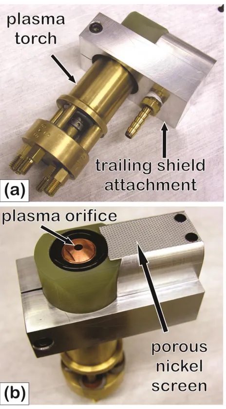
Figure 3.2: Photographs of one of the plasma arc torches fitted with the trailing shield device. ... 38
Figure 3.3: The traversing welding fixture with magnesium specimens clamped in place. ... 41
Figure 3.4: A Batch 1 specimen prior to welding. ... 44
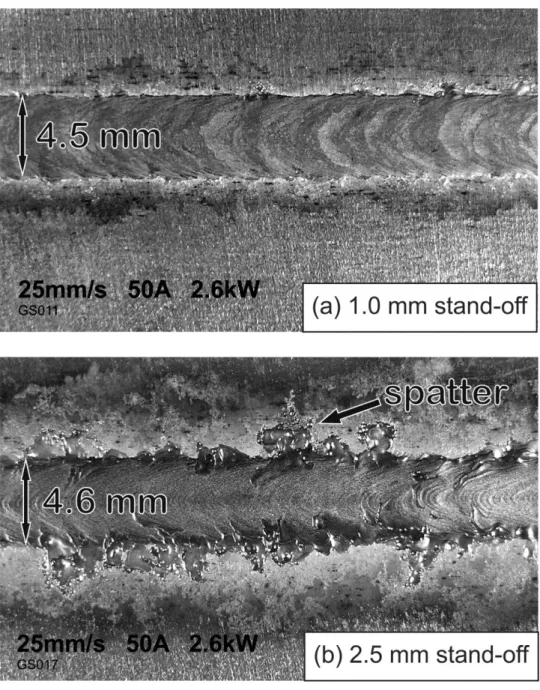
Figure 3.5: Test welds made at stand-off distances of (a) 1.0 mm and (b) 2.5 mm. ... 47
Figure 3.6: Sections removed from welds in 3 places. ... 50
Figure 3.7: Standard sized ASTM tensile specimen geometry and orientation... 52
Figure 3.8: Sub-sized tensile specimen dimensions and orientation within the weld specimen. ... 53
Figure 4.1: (a) Blowholes form at regular intervals along the weld (b) A critical weld width of 3 x sheet thickness resulted in blowholes. ... 56
Figure 4.2: Incomplete fusion defect in a DSAW weld made in AZ31 Mg sheet ... 58
Figure 4.3: Window of primary welding parameters resulting in acceptable welds ... 59
Figure 4.4: Batch 1 weld widths plotted against heat energy per unit length, HJ. ... 61
Figure 4.6: SEM image of the spatter marks at the weld toe. ... 65
Figure 4.7: Schematic representation of the thermal conditions in the 2 welds shown in Figure 4.5. . 66
Figure 4.8: Gross porosity in the fusion zone caused by hydrogen bubbles. ... 69
Figure 4.9: Another example of gas porosity pores connected with an oxide stringer. ... 70
Figure 4.10: Optical micrograph of the AZ31B-H24 base metal. ... 71
Figure 4.11: Optical micrograph of the microstructure in the heat affected zone ... 73
Figure 4.12: Photomicrograph showing the transition from the HAZ to the fusion zone. ... 74
Figure 4.13: Optical micrographs of the fusion zone of a typical weld.. ... 76
Figure 4.14: SEM image of the microstructure of a typical fusion zone. ... 77
Figure 4.15: Hardness profile across a weld... 78
Figure 4.16: Measured base metal tensile properties. ... 79
Figure 4.17: Transverse UTS results at different welding speeds. ... 82
Figure 4.18: Fracture surface of a typical 12.5 mm wide transverse tensile test specimen. ... 83
Figure 4.19: SEM images of the fracture surfaces of a typical transverse tensile test specimen ... 84
Figure 4.20: Longitudinal tensile test weld parameters on the process map ... 86
Figure 4.21: Effect of welding speed on yield stress. ... 88
Figure 4.22: Effect of welding speed on UTS. ... 89
Figure 4.23: Effect of welding speed on maximum elongation... 89
Figure 4.24: High magnification SEM image of the microstructure in the weld fusion zone ... 91
Figure 4.25: SEM images of the fusion zone: (a) welding speed 12 mm/s (b) 90 mm/s. ... 93
List of Tables
Table 1.1: Relevant structural properties of magnesium, aluminum and steel.. ... 1
Table 1.2: Thermo-physical properties of magnesium, aluminum and steel. ... 4
Table 3.1: Nominal and measured compositions of the AZ31B-H24 magnesium alloy. ... 43
Table 3.2: Secondary welding parameters used in these experiments. ... 48
Table 4.1: Measured base metal tensile properties and ASM Handbook [2] published values. ... 80
Table 4.2: Summary of results from transverse tensile testing of Batch 2 welds. ... 81
Table 4.3: Summary of results from longitudinal tensile tests of Batch 3 welds. ... 87
Chapter 1
Introduction
1.1 Light Alloys for Automotive Applications
For many years, automotive manufacturers have pursued strategies to achieve better fuel economy in the vehicles they produce. An important approach to improving fuel efficiency has been to reduce the overall mass of the vehicle and this has involved using lighter weight materials in all components wherever possible. Lightweight structural alloys such as aluminum and magnesium have been the focus of much research as candidates to replace heavier steel in many different automotive components [1]. Table 1.1 lists some relevant properties of representative alloys of aluminum, magnesium and steel. The difference in these properties, between the three materials, is the driving force behind the interest in increasing the use of light alloys in automotive structures.
Table 1.1: Relevant structural properties of magnesium, aluminum and steel. Source: ASM Handbook [2]. Property Magnesium AZ31B Aluminum 5182 Steel 1025 Density (g/cm3) 1.77 2.65 7.8
Yield stress (MPa) 220 250 300
Specific strength (MNm/kg) (yield stress / density)
124 94 38
Comparing the specific strengths of the three materials strongly suggests that magnesium is the better choice from a strength-to-weight point of view. Of course, this is an over simplification and the case for magnesium is not quite so compelling. Issues of cost, service temperature suitability and manufacturability have to be considered. Nonetheless, the fact that magnesium has a very low density and reasonable strength makes it an attractive choice for use in weight sensitive applications.
Automotive parts produced by casting processes have been among the first to undergo a transition from ferrous to light alloys. Cast iron automotive components have largely been replaced by aluminum castings unless very high temperature service is required. Further evolution is occurring as aluminum is replaced by magnesium alloys in some components such as transmission housings, oil pans, valve covers, seat frames, instrument panel frames and other internal parts [3], [4]. Volkswagen in Europe and General Motors in North America both use up to 20 kg of magnesium alloy components per vehicle, according to one alloy supplier, Magnesium Elektron [5].
Cast components have been among the first candidates to be considered for weight reduction because their mass is often considerable. The casting process imposes minimum wall thicknesses that are often greater than those required purely for mechanical strength. Hence, castings often end up by being stronger than necessary, at least in some places. This is particularly true of cast iron, with its high density and strength, compared to aluminum or magnesium [6].
The use of wrought semi-finished forms of light alloys such as extrusions and rolled sheet in automotive structures has seen much slower progress [7]. A small number of more expensive, low production volume cars have been designed with all aluminum body shells. Examples include the Audi A8, Acura NSX, Jaguar XJ & XK models and the 2013 Range Rover. Magnesium panels have only yet been seen in exotic, specialty vehicles. Further significant reduction in vehicle mass could be achieved if some of the sheet steel used in automobiles could be replaced with aluminum or better yet, magnesium alloys. This has been slow to realize, with mass-market vehicle manufacturers incorporating sheet aluminum only in the form of hood and trunk panels [8]. No examples could be found of magnesium alloys presently being used in body panels of modern, mass-market vehicles, although manufacturers continue to explore the possibilities [9]. Figure 1.1, taken from Friedrich [7], illustrates the path of anticipated progression from using magnesium to make castings for interior components, to gradually increasing its use to include sheet metal components. According to Friedrich, Volkswagen expects to see
the progression towards the use of sheet magnesium in automobiles as occurring over a time period greater than 10 years.
Figure 1.1: Progression of increasing use of magnesium in vehicle manufacture. (Adapted from Friedrich [7] and used with permission)
1.2 Obstacles to Increased use of Wrought Magnesium Alloys
There are several obstacles that impede the increased use of magnesium sheet products in the automotive industry. The most obvious is the present cost difference between a typical magnesium sheet and a sheet of mild steel. However, cost is dependent on production volume and it is reasonable to expect the presently high cost of magnesium alloy sheet to come down considerably, should production volume increase [1]. Moreover, direct material cost comparisons, whether on the basis of weight, volume or even
specific strength, is deceiving. Account has to be taken of the overall cost of manufacturing a given design [10].
Engineering obstacles to the increased use of sheet magnesium alloys in automobiles include poor room temperature formability [11], corrosion susceptibility [12] and a lack of expertise in welding and joining techniques [13]. One essential area of welding and joining technology that is presently lacking is the ability to make butt-joints in thin magnesium alloy sheet. Such joining of sheet components is required, for example, to make tailor-welded blanks for subsequent forming into structural components. Since the use of more tailor-welded blanks is likely to be a future trend [14], an efficient method of joining sheet magnesium, in the butt-joint configuration, is a prerequisite to its increased use by the auto and other transportation vehicle industries.
1.3 Considerations for Welding Magnesium Alloys
Magnesium has several important physical characteristics that affect its weldability. Among them are the thermo-physical properties listed in Table 1.2 These properties are meaningful when compared to those of a typical aluminum alloy and a low carbon steel.
Table 1.2: Thermo-physical properties of magnesium, aluminum and steel that affect the weldability of the alloy. Sources: ASM Handbook [2], Smithell’s Light Metals Handbook [15] and recent measurement experiments [16]. Magnesium AZ31B Aluminum 5182 Steel 1025
Melting point (liquidus) (K) 903 911 ~1770
Boiling point (K) 1370 2670 2750
Thermal conductivity, k (W/mK) 96 123 40
Specific heat, Cp (J/kgK) 1050 904 660
Density, (kg/m3) 1770 2650 7800
Thermal diffusivity, (m2/s) 5210-6 5110-6 7.810-6 Coef. of thermal expansion (1/K) 2610-6 2610-6 1410-6
1.3.1 Thermal Properties
Referring to Table 1.2, one of the most significant thermal characteristics of magnesium is that the melting and boiling points are very close together. This means that fusion welding is possible, provided the liquid is heated to within only a narrow temperature range between 903 K (630 °C) and 1370 K (1100 °C). The heat input has to be carefully controlled to maintain a temperature in this range. It would be very easy for the heat from any fusion welding process to raise the temperature of the metal above 1370 K (1100 °C) and for the metal to boil away. If this occurs, several consequences are possible: 1) the boiling liquid metal will spatter over the weld and welding equipment, 2) magnesium may condense on cooler surfaces adjacent to the weld, 3) magnesium vapour may escape the shielding gas envelope and turn into white smoke, as magnesium oxide welding fume or, in the extreme, 4) a magnesium fire may be ignited.
The thermal conductivity of magnesium is somewhat lower than that of aluminum, but together with a lower density and only slightly higher specific heat, this means that less heat is required to form and maintain a molten weld pool. This characteristic is described by the composite property, thermal diffusivity, which is defined as follows:
(1)
where is the thermal diffusivity (m2/s), k is the thermal conductivity (W/mK),
is the density (kg/m3) and Cp is the specific heat (J/kgK). Thermal diffusivity is easier to measure experimentally than thermal conductivity. It is also a more useful measure of the overall requirement for heat input in a fusion welding process, for a given material.
The coefficient of thermal expansion of magnesium is high, similar to that of aluminum, and this implies that distortion could be a problem in welding. Consequently, welding jigs and fixtures need to be
substantial and other techniques to alleviate distortion may need to be applied. The welding of thin magnesium alloy sheet is particularly susceptible to distortion problems.
1.3.2 Chemical Reactivity
Magnesium is well-known to be a highly reactive metal that will burn intensely in the presence of air if it becomes sufficiently hot to initiate combustion. To prevent fires, care must be taken to ensure adequate shielding of the molten weld pool surface with an inert shielding gas. Fine magnesium particles are used in pyrotechnics and are recognized as a fire hazard in machining and grinding operations involving magnesium alloys [17].
It is also widely known that magnesium corrodes rapidly in a damp environment. Bare magnesium items do not retain their shiny lustrous appearance for long, even in mild indoor conditions [12]. The magnesium metal initially reacts with atmospheric oxygen to form a thin layer of magnesium oxide, according to:
→ (2)
This reaction occurs quickly and the surface film, after 10 s in dry air, has been measured to be approximately 2 nm thick [18]. Unlike aluminum, the oxide layer formed on magnesium does not constitute a passivating protective barrier to further corrosion [19]. This is attributed to the reaction products having a Pilling-Bedworth ratio of 0.81. The thin layer of magnesium oxide is porous to oxygen molecules and allows for the reaction to continue, thickening the oxide layer until it becomes a visible, dull grey skin, 100 nm thick, several days later [18]. The oxide layer is also porous to water molecules and allows a second hydration reaction to occur if any water vapour molecules are present:
Hydrogen gas is evolved in this reaction and small bubbles can be seen to form on the surface of clean magnesium, a few seconds after immersion in distilled water. The surface layer that builds up on magnesium is, therefore, a combination of magnesium oxide and magnesium hydroxide. In a dry environment, the layer is predominantly magnesium oxide, but becomes predominantly magnesium hydroxide as more water vapour is available [20]. The magnesium hydroxide reaction product has a Pilling-Bedworth ratio of >2 and therefore forms a flakey, spalling surface layer. Magnesium hydroxide is hygroscopic and attracts more water molecules from the air, to form ( ) The 3 water molecules then react preferentially with more magnesium and the corrosion continues [20]. Spalling of the corrosion products from the surface leads to fresh magnesium metal being exposed to more corrosion. The surface layer continues to grow and eventually forms a loosely adhering white powdery layer.
The corrosion products described above are very harmful to any fusion welding process for several reasons. They neither dissolve nor melt in the liquid magnesium weld pool due to their high melting temperatures and they contaminate the weld by introducing discontinuities [21]. They are also abundant sources of elemental hydrogen that will readily dissolve in the molten metal weld pool during the welding process, leading to hydrogen porosity in the solidified weld metal. Accordingly, great care is required to remove all traces of hydrated oxides from the surface of magnesium alloy sheets prior to fusion welding. Careful shielding of the molten weld pool is also essential to prevent any further contact with atmospheric oxygen or humidity in the air during the welding process [21].
1.4 Mechanical Properties of Fusion Welded AZ31B-H24 Magnesium Alloy
Magnesium crystallizes into a hexagonal close packed (HCP) structure. At room temperature, slip occurs in the basal {0001} planes and twinning occurs in the pyramidal {1012} planes. Adjacent grains are unlikely to be favourably aligned to allow much deformation and inter-granular cracks may form. Consequently, magnesium alloys have low ductility at room temperature [22]. The AZ31B alloy typically
exhibits maximum elongations of about 10% - 12% in the H24 temper; perhaps rising to about 15% -18% in the annealed condition. These values are much lower than those of mild steel, which may easily exceed 30% [22].
At temperatures above 225°C, magnesium alloys have better ductility, as the more numerous prismatic {1100} planes become active and allow slip to occur in more directions. Adjacent grains are then more likely to have favourably aligned slip planes and ductility is much improved [22]. For this reason, magnesium sheet is almost always formed at elevated temperatures.
Magnesium alloys can rely on various strengthening mechanisms in order to achieve useful levels of mechanical strength. Solid-solution strengthening, by the addition of small amounts of aluminum or zinc is a common method of improving the strength of the pure metal. Strengthening by grain size reduction is another method to improve strength in wrought forms like rolled sheet [17]. Precipitation hardening by the formation of small, finely dispersed particles of hard intermetallic compounds is a third method of improving the mechanical properties of commercial magnesium alloys [23] [24]. The benefits that these grain size and precipitation strengthening techniques impart to the alloy are lost when the magnesium alloy is fusion welded, as the fusion zone metal is melted and re-cast. Partitioning and micro-segregation of the alloy components occurs upon solidification, so that locally, there is either too little or too much solute concentration for optimal solid-solution strengthening [25].
The fusion zone microstructure in an AZ31B magnesium alloy weld is normally dendritic, with rounded, non-facetted dendrites of solute-lean magnesium, surrounded by material much richer in solute. Most welding processes will produce large dendrites, but smaller dendrites are possible if the cooling rate is fast enough. The very last metal to freeze will have the highest solute concentration and may approach the eutectic composition of Mg -33wt%Al. Normally, coupled growth of the eutectic does not occur. Rather, a divorced eutectic will typically form with separate solute-rich -magnesium and a brittle intermetallic -phase, Mg17Al12 [17]. The -phase forms along grain boundaries and seriously degrades
the ductility of the alloy. Solidification shrinkage of magnesium can be enough to cause hot cracking in the resulting welds, especially in regions where the aluminum content is less than 6 wt% Al [25].
The adjacent partially melted zone and heat affected zone (HAZ) of an AZ31B magnesium fusion weld will undergo grain growth, to varying degrees, depending on the amount of heat conducted into the surrounding metal. Therefore, the strengthening derived from grain refinement or strain hardening during mechanical processing is also lost in the immediate vicinity of the weld. Finely dispersed second-phase particles of Mn5Al8 in the HAZ coalesce and grow, as a result of heating, to become fewer and larger, so that the precipitation hardening effect is also diminished [26].
1.5 Fusion Welding Processes for Magnesium Alloys
Wrought magnesium semi-finished forms have not traditionally been joined by welding, due to the considerations discussed in the preceding two sections. Joining by the use of aluminum rivets, was the process of choice for assembling sheet magnesium components used by the aerospace industry up to the 1960s [27]. However, riveting is a labour intensive process and some suitable welding technology was needed if magnesium was to gain acceptance outside of the defense industry, where cost is a lower priority.
Fusion welding of magnesium alloys grew out of the need to repair defects in magnesium alloy castings. Experience in making these repairs has shown that many magnesium alloys can be successfully welded, as long as proper methods are employed to account for the particular characteristics of magnesium alloys. These methods can be summarized into the following 4 points [21]:
1. Precise control of the heat input into the weld. 2. Scrupulous attention to the cleanliness of the weld. 3. Total shielding of the weld pool from the atmosphere. 4. Some form of mitigation against shrinkage distortion.
Gas Tungsten Arc Welding (GTAW) has been considered the cleanest of the traditional welding heat sources and as such, has been the natural choice of technology for welding such reactive metals as magnesium. It can be carried out manually, but great skill is required to manipulate the weld pool and therefore some form of automated welding system is more commonly used. Autogenous welds are possible if the fit-up is carefully prepared, otherwise filler metal strips can be laid in the groove [21].
Gas Metal Arc Welding (GMAW) has been the preferred technology for the welding of steel, due to the high deposition rates that are possible, the ease of automation and the energy efficiency of the process. However, the GMAW process suffers from inherent problems, if applied to magnesium. The filler wire must travel through the length of the arc column, during which time it is heated above its boiling point, resulting in spattering and evaporation loss. Research to adapt this process for magnesium alloys, using novel pulsed waveforms is ongoing [28]. Second is the problem of economically producing the filler wire. Magnesium wire is presently drawn down to size in a costly and time consuming process, involving many small draw steps with interspersed heat treatments [29].
Resistance Spot Welding (RSW) of magnesium alloys is quite feasible, given that the electrical conductivity is between that of aluminum and steel. However, the results can be inconsistent because the process parameters are very critical [30]. Also, it should be noted that the RSW process is applicable only to lap-joints, not the butt-joint configuration, required for making tailor welded blanks.
Laser welding of magnesium has received much attention over the years, as researchers attempt to take advantage of the high welding speeds theoretically possible with this high energy density heat source, operating in the keyhole mode [13]. However, laser welding systems are very capital intensive and laser welding speeds are presently limited by the tendency to form gas porosity and undercut defects at high speed when welding magnesium alloys [31]. Various combinations of laser-arc hybrid heat
sources have also been investigated and the results look promising, as the synergistic effect between the laser beam and the arc becomes better understood [32].
All of the above welding technologies are normally applied to one side of the work-piece. When welding magnesium sheet material, however, some form of shielding protection from the atmosphere is also required for the back surface of the sheet. This may involve a variety of different arrangements, but they all require access to the reverse side of the sheet. One relatively new welding method that could be used to advantage to join magnesium sheet in the butt-joint configuration, while overcoming many of the deficiencies of other welding processes when used to weld magnesium, is the Double-Sided Arc Welding (DSAW) process.
1.6 Double-Sided Arc Welding (DSAW)
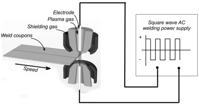
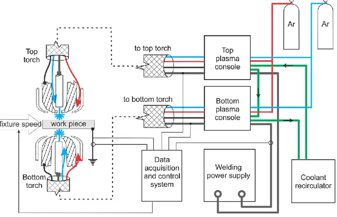
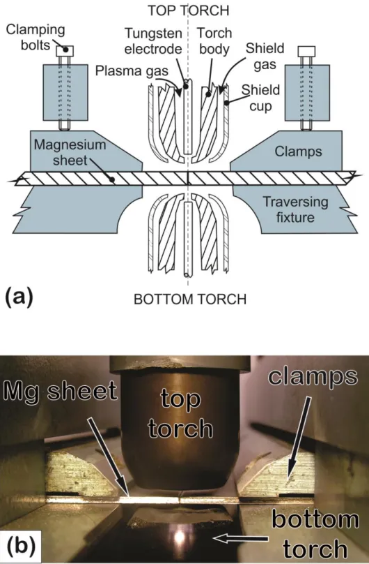
The Double-Sided Arc Welding (DSAW) process was invented and patented by Zhang and Zhang [33], at the University of Kentucky in 1999. Shown schematically in Figure 2, it involves the use of two welding torches, one on each side of the work. The torches are connected in series to one power supply, forming one welding circuit with an arc established between the two torches. When the work is fed through the arc column, the arc splits into 2, with the sheet material in between. The welding current passes through the thickness direction of the metal, thereby applying heat and shielding to the top and bottom surface of the joint simultaneously.
The DSAW system can be configured to use either GTAW or Plasma Arc Welding (PAW) torches. Plasma Arc Welding (PAW) is a further development of GTAW in which the arc plasma is directed, in the form of a jet, through a small orifice at the tip of the welding torch [34]. PAW torches are more fully described in the following Sub-Section 1.6.1.
Figure 1.2: Schematic representation of the double-sided arc welding process with 2 PAW torches. The DSAW process was originally applied by Zhang & Zhang [35] to making butt-joint welds in thick aluminum plates in the vertical-up position, using keyhole-mode welding. Applications include the welding of process industry tanks and other vessels as well as ship hull plate made in a range of aluminum, steel and stainless steel alloys [35]. It was subsequently adapted to the horizontal position, conduction-mode welding of AA5182 aluminum alloy thin sheet by Kwon & Weckman and others at the University of Waterloo [36] [37] [38] [39] [40] [41].
The DSAW process has several inherent advantages that can be usefully applied to the welding of thin magnesium sheet in the butt-joint configuration, as envisioned in this study:
1. The process can produce a very symmetrical weld with little or no angular distortion of the sheet material [42].
2. Complete joint penetration can be achieved with a fairly narrow weld, since there is a heat source on both surfaces of the metal.
4. The electric arc that provides the heat source is also responsible for the cathodic cleaning action on the surface of the sheet; an important advantage that does not occur with a laser heat source [43].
5. The process uses mature technology that is already available to industry and is well understood. Investment in capital intensive equipment is not required in order to use the process. An existing welding power supply can be connected to appropriate torches for minimal cost, as an inexpensive way to experiment with the process.
Many variations of heat sources have been investigated in the last decade in order to advance the state of the art of welding magnesium alloys. So far, no studies have been published on the joining of magnesium alloy sheets using the DSAW process.
1.6.1 Plasma Arc Welding (PAW)
Plasma Arc Welding (PAW) is a further development and refinement of GTAW that involves directing a stream of ionized argon plasma past a tungsten electrode and through a small orifice in the welding torch tip, onto the weld surface. In this way, the arc is constrained into a narrow jet of plasma and a higher energy density is achieved. The plasma arc is narrower and more columnar in shape than the unconstrained GTAW arc, which is typically bell-shaped. PAW torches produce a high energy-density heat source, without the high costs associated with a laser system. They are capable of operating in the conventional conduction welding mode and also the keyhole welding mode, when the power is increased [44].
Figure 1.3 shows the construction details of a PAW torch and illustrates the principle of operation. Plasma gas passes through the narrow passage between the electrode tip and the torch body. Starting the plasma arc requires a pilot arc to be struck between the electrode and the torch body.
Figure 1.3: Detail of a PAW torch.
The pilot arc heats the plasma gas to an ionized, conducting state. From this point, the jet of plasma gas is an electrical conductor and the main arc can then switched on. The main welding arc current flows between the electrode, through the conducting jet of plasma, and the work-piece [34].
The added complexity of the PAW system brings with it another set of welding process variables that need to be established and controlled. However, the DSAW system takes advantage of the characteristics of the PAW torch to permit a relatively long welding arc to be easily switched on and off. The flow of plasma gas through the orifice involves the considerations of orifice geometry, plasma gas pressure and plasma gas flow rate. These variables have been found to be critical to the success of the process [45]. The arc length is the sum of the torch to workpiece distance (referred to as the stand-off distance) and the distance between the electrode and the orifice (known as the set-back distance) [34]. In the interests of process efficiency, a short arc is desirable, in order to keep the arc voltage as low as possible for a given current. There are practical limits to how short the arc can be set. Small set-back distances require the electrode tip to be ground to a truncated cone in order not to contact the orifice [36].
These narrowed electrode shapes do not conduct heat away from the tip as well as blunt electrodes. They are prone to the electrode tip melting into a ball-shaped end, with possible electrical short-circuiting between the electrode and the torch body [46]. The torch stand-off distance also has a lower limit. There must be sufficient distance between the torch and the weld pool surface to prevent any possibility of short-circuiting between the torch body and the work-piece.
PAW torches are capable of achieving high energy densities that approach those of lasers and are capable of operating in both conduction-mode and keyhole-mode, at higher powers [34]. In keyhole mode, they can produce deep, narrow welds at high welding speeds. PAW process equipment is available at considerably lower capital cost than equivalent size laser systems. For this reason, it is an attractive alternative to laser welding. However, the plasma-arc is not as stable as a laser beam and requires careful adjustment of parameters. Frequent maintenance of the electrode and plasma orifice is also required [47].
1.6.2 Arc Physics
It has long been recognized that the heat generated in a welding arc is not shared equally between the anode and the cathode surfaces. In a DC welding arc, about 70% of the heat is produced at the anode, where the electrons give up their kinetic, thermal and work function energies to the surface of the material they strike [43]. For this reason, the workpiece is often made to be the anode (referred to as DC Electrode Negative or DCEN) when GTAW welding. This arrangement takes advantage of the anode heat, rather than have it wasted in the tungsten electrode.
There is another physical process, referred to as cathodic cleaning or cathodic etching, which is important when fusion welding aluminum and magnesium alloys. These alloys have tenacious coherent oxide surface layers, with melting points well above the melting point and even boiling point of the alloy. Cathodic cleaning occurs on the cathode surface and involves the stripping away of the solid surface oxides from the metal [48]. The precise mechanism behind cathodic cleaning is still the subject of
investigation and debate, but it is likely to involve electrons leaving the electrically conducting cathode surface and dislodging the attached non-conducting oxide layer on the way out. Another theory suggests that the oxide layer is removed as a result of the bombardment of the cathode surface by the more massive positive argon ions from within the plasma gas [43]. When welding alloys such as aluminum and magnesium, it is possible to make the work-piece the cathode (referred to as DC Electrode Positive or DCEP), in order to promote cathodic cleaning of the weld surface. In this case, a higher welding power is used, to compensate for the lower heat in the cathode and a heavier tungsten electrode in a water-cooled torch is used to carry away the extra heat evolved at the anode [47].
1.6.3 Variable Polarity Wave-forms in Welding
In order to take advantage of both anode heat and cathodic cleaning simultaneously, some form of alternating polarity can be used. In the past, this has involved using a simple welding transformer to produce a 60 Hz line frequency, sinusoidal AC waveform. The resulting welding circuit spends equal time in the electrode-negative and electrode-positive modes, giving a large degree of cathodic cleaning and heat balanced between workpiece and electrode. However, the sinusoidal waveform is not ideal for welding, because a significant fraction of the AC cycle time is spent at low current when the polarity crosses zero. The arc extinguishes during these low current periods and is, therefore, discontinuous and not very stable [47].
Modern power electronic components have allowed welding power supplies to produce square-wave AC outputs, which have almost no switch-over time, as shown in Figure 1.2 [49]. The arc is essentially continuous and switches polarity without extinguishing. Further, the square-wave is not restricted to the 60 Hz line frequency, nor must it be balanced in time and magnitude. Most welding power supplies now permit frequency adjustment from several tens, to several hundred Hz. More importantly, they also provide pulse width modulation to control the fraction of time spent in electrode
positive or electrode negative modes. The fraction of time spent in electrode negative mode is denoted by , and is calculated thus:
(2.1)
where tEN is the time spent in a periodic square wave form with electrode negative and tEP is the time spent
with electrode positive polarity. The magnitude of the welding currents in EP and EN is also adjustable. The EN polarity fraction is denoted by , and is defined as:
| |
| | | |
(2.2)
where I is the welding current and the subscripts have the same meaning as in Equation 2.1. By adjusting and , the degree of welding penetration and cathodic cleaning action can be controlled. These parameters were originally investigated by Okada et al. [50] in the early 1980s.
1.7 Research Objective and Thesis Organization
The DSAW process has been shown to be a feasible and practical method for producing high quality, conduction-mode, butt-joint configuration welds in thin aluminum sheet. Magnesium alloys present similar welding challenges, having thermo-physical and oxide properties that are similar to those of aluminum. There are several potential advantages in the DSAW process that could be useful in the welding of magnesium alloy sheet. Advantages, such as a well-controlled heat source; cathodic cleaning; shielding on both sides; symmetrical weld profile; minimum angular distortion, could all be of value, yet the DSAW process has not previously been applied to magnesium alloys. Therefore, the objective of this research was to explore the weldability of AZ31B-H24 magnesium alloy sheet in the butt-joint configuration using the DSAW process.
Process parameter ranges were identified that produce acceptable welds and optimal welding parameters were found. The resulting welds were examined and characterized using standard metallurgical laboratory techniques. The mechanical properties of the welds were determined by hardness testing, transverse tensile testing and longitudinal tensile testing of the weld fusion zone metal, distinct from the surrounding base metal.
In the following Chapter 2, a review of the current state of knowledge in the field of welding magnesium alloys is presented. Chapter 3 describes the experimental work carried out as part of this research. Details of the welding equipment, materials and procedures are given. The activities involved in the analysis of the welded joints are described. Chapter 4 includes all of the experimental results reported in this work. The results are discussed in the context of the existing published work in the field. Finally, a summary of the work and the conclusions that can be made are presented in Chapter 5.
Chapter 2
Literature Review
2.1 Welding Processes for Magnesium Alloys
Magnesium alloys are described as being “readily welded” in the Welding Handbook of the American Welding Society [51]. Specifically, AZ31B magnesium alloy is described as having “excellent” weldability by both Resistance Spot Welding (RSW) and Gas Tungsten Arc Welding (GTAW). Other possible processes that might be used to weld this alloy include electron beam welding, laser beam welding and stud welding.
This chapter summarizes the present state of research into welding methods that are suitable for joining AZ31B magnesium alloy, particularly with a view to efficient mass production. The surveyed literature describes the welding of AZ31B magnesium alloys as being generally prone to: 1) solidification shrinkage cracking, 2) porosity defects and 3) weld contamination due to the extreme reactivity of magnesium at high temperatures. All of the research described in the literature has focused on identifying ways to overcome the problems in these 3 areas.
2.1.1 Resistance Spot Welding (RSW)
Resistance Spot Welding (RSW) of lap joints is by far the most common method of assembling the sheet metal components of manufactured products, including automobile bodies. Figure 2.1 shows a schematic representation of the process. It involves applying force to and electrical current through overlapping sheets of metal via 2 water-cooled copper electrodes. The resulting resistive heating melts the sheet metal at the sheet interface to form a fusion zone or weld “nugget”. RSW is the mainstay of the automobile assembly industry and is widely applied to welding of sheet steel in the lap-joint configuration. RSW is extremely efficient, when applied to steel, in so far as it is very fast, uses simple and fairly low-cost equipment, and is tolerant of considerable variance in welding parameters and part fit-up quality [52].
Figure 2.1: Schematic representation of the Resistance Spot Welding (RSW) process.
The RSW process can also be applied to aluminum; however, in that case, the process becomes somewhat less attractive, due to material properties that are less conducive to the RSW process. Much higher electrical currents are required in aluminum, to achieve the same heating effect as in steel, due to aluminum’s low resistivity. Thus, bigger and more expensive power supplies are required to resistance spot weld aluminum alloy sheet. There is also much greater erosion and wear of the electrode tips, which adds to the overall process cost. Nonetheless, RSW is still the process of choice for assembling over-lapping sheet aluminum components, as used by the auto industry [53].
There is much less published research available on RSW of magnesium alloys, reflecting the small amount of magnesium sheet metal used by industry. Recent interest in magnesium for automotive structures has started to change this situation and the number of published works is increasing. Magnesium alloys can be joined by RSW as long as the parameters are carefully set to account for the electrical resistivity, thermal diffusivity and yield stress of the metal [54].
In 2012, Babu et al. [55] reported that the RSW heat input parameters were quite sensitive when welding magnesium alloys and that expulsion of liquid metal would occur at higher than optimal heat input, thus compromising the mechanical strength of the joint. They also noted that inclusions of
contaminants in the weld could be a problem and that shrinkage of the fusion zone on solidification could result in a collapsed zone at the center of the nugget, thereby weakening the joint.
Xiao et al. [23] described the solidification processes within the weld nugget of RSW welded magnesium alloys in detail. They recognized the role of very small intermetallic particles of Mn5Al8 as nucleation sites to promote a fine grain structure within the weld nugget and went on to experiment with inoculation of the weld site with pure titanium powder to enhance this grain refining effect [56]. The optimal size of the inoculating particles was established and an improvement in the microstructure of the resulting welds was reported.
It should be noted that RSW is applicable to the lap-joint configuration only. Therefore, although RSW will certainly find application in some areas of sheet metal assembly, it is not a candidate to produce butt-joint configuration welds, as would be required in the production of tailor-welded blanks.
2.1.2 Friction Stir Welding (FSW)
Friction Stir Welding (FSW) is a solid-state welding process in which a rotating tool is used to apply frictionally generated heat and plastically deform the metal to form an autogenous weld joint. Figure 2.2 shows the process schematically in the butt-joint configuration. A wide variety of tool geometries have been tried [57] but most tools consist of a pin with a helical profile on the outside that plastically stirs the metal. The tool has a shoulder which is kept at the height of the material surface and leaves a flat processed weld surface behind the slowly advancing tool. The lap-joint configuration is also possible, by making the pin long enough to protrude into both layers of the material. The FSW process results in a processed zone of highly deformed material with a very fine grain structure. Normally, the heat generated is sufficient to soften the metal but not melt it. The process has certain advantages over fusion processes, in that the metallurgical defects normally associated with solidification are avoided [57]. This is a
particularly attractive feature of the process, when applied to magnesium, compared to conventional fusion welding processes [54].
Figure 2.2: Schematic representation of the Friction Stir Welding (FSW) process.
In recent work by Afrin et al. [58], the strength of friction stir welded magnesium alloys was examined. The resulting very fine grain structure of the mechanically processed zone suggests that the process could produce a very strong joint. They found that although the mechanically processed zone had a higher hardness than the base metal, there was significant softening of material in the heat affected zone (HAZ). Consequently, upon tensile testing, all of the joints failed in the HAZ.
Kostka et al. [59] used the FSW process to make dissimilar butt-joint welds between sheets of magnesium AZ31B and aluminum AA6040. They found that the relatively low temperatures attained during FSW reduced the tendency to form intermetallic compounds that are usually associated with welding magnesium to aluminum. As such, the process has advantages when applied to Al-Mg dissimilar joints.
Commin et al. [60] looked more closely at FSW of the AZ31B magnesium alloy, with a view to using the process to join large magnesium panels in aerospace applications. The strain and temperature fields on both the advancing and retreating side of the rotating FSW tool were investigated. They also established a process parameter window and concluded that optimal microstructure resulted when the
processed zone reached a temperature 670 K (400 °C). The authors calculated that FSW welds in AZ31B magnesium alloy may suffer from considerable residual stress in the surrounding material, especially on the retreating side of the tool. No details of grain growth in the HAZ were reported and the mechanical properties were established by micro-hardness measurement only. The highest welding speed reported was 30 mm/s.
All of the researchers above have recognized that the FSW process is limited by a slow welding speed and the high mechanical forces that have to be resisted by robust welding fixtures [58] [59] [60] [61]. Hence, magnesium alloys, which are relatively soft and in any case require slow welding speeds, make good candidates to be welded by this process. It may be noted that the reported problems of grain growth in the HAZ and residual stress in the surrounding metal are essentially the same as those experienced in fusion welding processes.
Friction stir welding (FSW) is a promising solid-state welding process that can be applied to lap-joint or butt-lap-joint configurations without the attendant metallurgical problems of solidification in the weld zone. However, it is presently limited to high value, specialty items, due to slow welding speeds and the requirement for special fixtures to withstand the considerable contact forces involved [60].
2.1.3 Gas Metal Arc welding (GMAW)
Gas metal arc welding (GMAW) is not normally used with magnesium alloys and most authorities, including the American Welding Society, state that magnesium cannot be welded using the conventional GMAW process [51]. The main difficulty stems from the low boiling point of magnesium, which causes the filler wire to vaporize explosively as it is fed into the arc plasma. This prevents transfer of liquid metal to the weld pool in a stable stream of small droplets. The result is extreme spatter and inconsistent metal deposition [62]. Nonetheless, the GMAW process is attractive to industry for several reasons and has been widely applied to the welding of steel and aluminum alloys. It offers the advantages of high
deposition rates, energy efficiency, tolerance of moderate gaps and the ability to introduce desirable alloying elements into the weld metal, via the filler wire. The GMAW process is also readily automated [63].
The problem of adapting the GMAW process for use with magnesium alloys has been studied principally by Rethmeier et al. [64], Song et al. [62] and Gao et al. [65]; the latter investigating a laser-GMAW hybrid system. These researchers all note the requirement to precisely control the heat input, such that the filler wire melts without boiling. The approach has been to use a multi-level, pulse-modulated waveform to control the electrical power input. These experimental power supplies produce pulsed waveforms consisting of a very short, high current pulse, sufficient to melt a section of wire, followed by a longer pulse of much lower current. The low current pulse facilitates metal transfer with minimal heat input, and avoids boiling the filler wire [66]. It has only recently become feasible to produce these complex waveforms, with new developments in power electronic switching devices, such as the Insulated Gate Bipolar Transistor [49]. Such sophisticated waveform control is likely to become available in commercial welding power supplies in the near future.
Gas metal arc welding (GMAW), favoured by industry for its high productivity when applied to steel, is not yet properly adapted for use with magnesium alloys. Research focuses on pulsed waveforms that can control the heat input to avoid boiling of the filler wire [62]. Associated research is also required to allow economical production of filler wire materials for magnesium alloys [29].
2.1.4 Gas Tungsten Arc Welding (GTAW)
The Gas Tungsten Arc Welding (GTAW) process has long been considered the natural choice for welding reactive metals such as Al, Mg and Ti due to its characteristic ability to provide good shielding of the weld from contamination [34]. Square-wave AC welding current is always used in these cases, in order to take advantage of the cathodic cleaning action, described in Chapter 1. The process has, therefore, been
extensively researched by those interested in welding magnesium alloys [67] [68]. Often, the research involves comparing welds made using GTAW to those made by other welding processes [61].
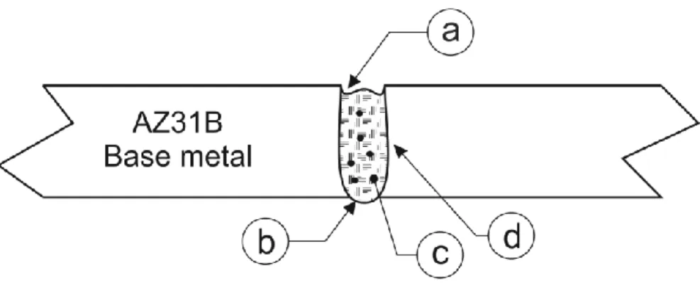
Figure 2.3 shows a representation of the GTAW process, including the resulting full penetration, butt-joint weld made in AZ31B magnesium alloy sheet, as reported in the surveyed literature. An electric arc (a), often bell-shaped, is maintained between a non-consumable tungsten electrode (b) and the work. Inert shielding gas (c) is fed through a surrounding nozzle (d) to blanket the molten weld pool and the surrounding hot base metal with a protective atmosphere. The resulting weld will usually have a smooth top surface as shown at (e). This surface is likely to be slightly under-filled because of magnesium loss to evaporation and the small amount of drop-through shown at (f). The fusion zone (g) is likely to approximate a semi-circle, typically twice as wide as it is deep, depending on the patterns of fluid flow within the molten weld pool [69]. A heat affected zone (HAZ) (h) will extend to some distance into the base metal, on either side of the fusion zone, where the heating and cooling that takes place during the welding process has altered the base metal microstructure and properties.
In 2002, Sun et al. [70] compared welds made in AZ31B magnesium alloy using GTAW, with others made using laser heat sources. With both welding processes, the importance of surface preparation and proper shielding of the hot metal during welding were noted. The authors described the now well established differences in the microstructure of welds made with low (GTAW) and high (laser) energy density heat sources. They noted that GTAW welds were characteristically shallow with respect to width, had a significant HAZ adjacent to the weld and a course grained, dendritic fusion zone. Conversely, laser welds could be made deep and narrow, had a very small HAZ and a fine grained fusion zone.
In 2006, Liu et al. [67] experimented with cold-wire fed automated GTAW welds in AZ31B magnesium alloy. They compared the welds made with filler wire to those made autogenously and reported that weld penetration was deeper if filler wire was not used but did not elaborate further. The welds without filler failed in the HAZ, whereas those made with AZ61 filler wire failed in the fusion zone. The authors attributed this difference to larger fusion zone grain sizes in the joints with filler wire, due to the extra heat input (and associated lower cooling rate) required to melt the wire. They did not address the possibility that the AZ61 filler wire had raised the aluminum content of the AZ31 base metal in the fusion zone and that this had caused more brittle -phase Mg17Al12 material to be formed at the grain boundaries.
In 2010, Padmanaban et al. [61] compared the mechanical properties of welded joints of AZ31B magnesium alloy made by GTAW, FSW and laser processes. They reported joint efficiencies of 85% for GTAW joints and 98% and 99% for FSW and laser joints, respectively. They did not specify the temper condition of the base metal, but their stress-strain curve for the base metal (UTS: 190 MPa) suggests it was fully annealed. The GTAW welds all failed in the HAZ and they state that this was due to the considerable grain growth that occurred. Grain sizes were not quantified, but their micrographs show grains of around 40 m in size.
In subsequent work, Padmanaban et al. [71] reported on the fatigue behaviour of these same welded joints. They found that the GTAW joints were somewhat less resistant to fatigue than either FSW or LBW welded joints. Specifically, they reported a 12 % higher fatigue exponent in the Paris power law [72] for GTAW welds than for laser welds. They attributed this difference in fatigue performance to differences in grain size in the fusion zones of the welds. The GTAW welds had larger FZ grains than the welds made with the other two processes. This is a reasonable suggestion but the authors did not quantify the difference in fusion zone grain sizes between the processes.
Gas tungsten arc welding (GTAW), used with a variable polarity square wave-form, continues to be a suitable process for welding magnesium alloys in maintenance and repair operations. However, low power and low welding speeds are required in order to avoid the typical problems of hot cracking and porosity. The process is, therefore, not very attractive for high volume manufacturing applications.
2.1.5 Laser Beam Welding (LBW)
The use of lasers as a heat source for welding magnesium has been studied extensively [13] [31] [73] [74] [75]. A 2006 review by Cao et al. [13] provides a thorough overview of the main issues, including a description of the key-hole mode of welding, in which a deep pocket of metal vapour is formed and maintained in the weld pool. The traditional low energy density arc welding power sources, when applied to wrought magnesium alloys, all result in the formation of a significant HAZ and a fusion zone microstructure with larger grains than the base metal. These effects naturally lead to lower mechanical properties in the welded joint. However, the use of a high energy density heat source, such as a laser beam, has the potential to leave practically no HAZ and a smaller fusion zone grain size than that of the base metal [13]. On these grounds, laser welding offers the possibility of welds with mechanical properties superior to those of the surrounding base metal. Unfortunately, other aspects of this high speed, high energy-density process are more detrimental to the resulting welded magnesium alloy joint.
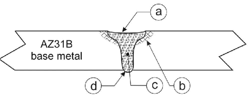
Figure 2.4: Typical keyhole-mode laser butt-joint weld made in AZ31B.
Figure 2.4 shows a cross-section of a typical keyhole-mode laser butt-joint weld, made in AZ31B magnesium alloy, as reported in the surveyed literature. The undercut top surface (a) is much more pronounced in a laser weld, compared to a typical GTAW weld due to vaporization of the magnesium. A small amount of drop-through (b) is to be expected in a full-penetration weld. Hydrogen porosity and occluded vapour porosity (c) has been reported as a problem by many researchers investigating laser welding of magnesium alloys [31]. It appears that the deep, narrow weld profile, coupled with the high welding speed, prevents the gas bubbles from escaping the weld pool before it solidifies [74]. The HAZ is typically very narrow (d) or even indiscernible, at a macro-scale.
In 2008, Coehlo et al. [73] gave a detailed report of their experiments in producing autogenous butt-joint welds in AZ31B magnesium alloy at speeds of up to 90 mm/s, using a 2.2 kW Nd:YAG laser beam. They achieved narrow, full-penetration welds, with minimal porosity and good cross-sectional profile. There was no significant undercut or drop-through. These welds had a very fine fusion zone grain structure and good mechanical properties. In transverse tensile testing, fracture always occurred in the base metal, indicating a high quality fusion zone. They also performed longitudinal tensile testing on miniature specimens extracted from the fusion zone. These tests confirmed the superior mechanical properties of the fusion zone metal. Maximum elongation was 20% compared to 24 % for the annealed AZ31B base metal.
In 2010, Kim et al. [74] reported on the use of a Nd:YAG laser to make autogenous welds in sheet AZ31B magnesium alloy in the butt-joint configuration. After experiencing initial difficulties obtaining adequate shielding conditions, they achieved visually acceptable welds at welding speeds between 50 mm/s and 100 mm/s using a beam power of around 1.5 kW. Joint efficiencies were reported to be up to 100 % of base metal properties and porosity was negligible. The microstructure in the fusion zone was not reported, but macrographs of the weld profile showed a characteristic narrow, full-penetration weld with good surface appearance.
Laser welding using a Nd:YAG laser beam directed through a fiber-optic cable offers the possibility of welding magnesium in the keyhole-mode, due to a very high energy density. Increased welding speeds are possible as a result [13]; however, other defects remain, such as excessive vaporization and poor weld bead quality. Geometrically poor weld profiles with undercut and drop-through have been reported when laser welding magnesium alloys [46]. Gas porosity is generally a bigger problem when laser welding, because the gas bubbles have less opportunity to escape the weld pool [74].
The use of a high energy density laser heat source offers the advantage of higher welding speeds than those achievable with arc-based heat sources. Other desirable weld features may include a finer fusion zone microstructure and a smaller HAZ. However, the susceptibility of magnesium welds to hydrogen porosity is worse, under these conditions. Laser welds are prone to undercut and drop-through defects that inevitably occur in mass production. Finally, the high capital cost of laser welding equipment must be considered as a disadvantage to the process.
2.1.6 Hybrid Laser-Arc Welding
Hybrid laser-arc welding refers to the simultaneous use of both laser and arc heat on the same weld pool surface in order to take advantage of the desirable characteristics of both heat sources. It has been reviewed in 1999 by Tusek and Suban [76], 2005 by Bagger and Olsen [77] and in 2009 by Ribic et al.
[78]. The advantage of the hybrid heat source lies in the synergy between the laser beam and the arc plasma that results in weld characteristics superior to those obtained from either heat source separately [79]. The resulting weld profile is a combination of the characteristic profiles of laser and arc welds and is shown in Figure 2.5.
Figure 2.5: Cross-section through a typical laser-GTAW hybrid butt-joint weld in AZ31B magnesium alloy sheet.
In the upper part of the weld, the arc heat flux dominates and a wide, shallow weld pool forms, with a characteristic smooth surface at (a). A small HAZ forms in the top portion of the sheet as a result of heat conduction into the surrounding base metal at (b). In the lower part of the weld, the laser heat dominates, and the fusion zone is narrow (c), without any significant HAZ. The lower surface of the weld is much the same as the laser weld, with some drop-through (d).
The action of the laser beam passing through the arc plasma has a further effect of anchoring the arc to a single spot, rather than it being in constant movement over a given area. This arc stabilizing effect has been investigated and reported by Chen and Liu [80], Mahrle and Beyer [81] and others. Chen and Liu [80] have also proposed a physical mechanism for the stabilizing effect. This effect is important, because it is a method of constraining the arc heat source to a smaller area than it would otherwise occupy. The arc is therefore of a higher energy density. Also, by eliminating the tendency for the arc to wander, spattering is greatly reduced. Hybrid laser-arc welds are somewhat more tolerant of gaps between
the parts than a similar laser weld [78]. The augmentation of a welding arc with a laser beam may not require a very powerful laser beam to be effective. Liu et al. [32] used a 300 W Nd:YAG laser to augment a 100 Amp GTAW arc and reported all of the above beneficial results.
Obviously, a hybrid laser-arc welding system is a complex piece of equipment with many additional parameters to be adjusted. It is also expensive to acquire and maintain, due to the high cost of lasers. Such systems are likely to be attractive to industry, only if the capital cost of laser equipment continues to decline.
Hybrid laser-arc welding has been shown to offer the beneficial characteristics of both laser and arc heat sources. The synergy is based on the attraction of the arc to the laser spot [80]. The laser constricts and confines the electric arc to one location and effectively increases the energy density of the arc. The electric arc, meanwhile, imparts a smooth top surface to the weld bead and allows the escape of hydrogen bubbles more easily. It is possible that some form of laser-augmented electric arc welding will eventually emerge as the favoured technology for welding magnesium, if the cost of laser power supplies continues to fall.
2.1.7 Double-sided arc welding (DSAW)
The double-sided arc welding (DSAW) process was introduced earlier, in Section 1.4 and shown schematically in Figure 1.2. The configuration can be used with either 2 GTAW torches, 2 PAW torches or one of each. Whichever type of torch is selected, the process has the advantage of adding heat to the weld simultaneously from both sides of the sheet.
The DSAW process was successfully applied by its inventors, Zhang and Zhang [33], for key-hole mode welding of steel and aluminum plates in the vertical-up position and showed that welds with greater depth-to-width ratio could be produced by the double-sided configuration than possible by the
![Table 1.1: Relevant structural properties of magnesium, aluminum and steel. Source: ASM Handbook [2]](https://thumb-us.123doks.com/thumbv2/123dok_us/1389961.2686170/12.918.137.784.620.805/table-relevant-structural-properties-magnesium-aluminum-source-handbook.webp)
![Figure 1.1: Progression of increasing use of magnesium in vehicle manufacture. (Adapted from Friedrich [7] and used with permission)](https://thumb-us.123doks.com/thumbv2/123dok_us/1389961.2686170/14.918.133.755.273.701/figure-progression-increasing-magnesium-manufacture-adapted-friedrich-permission.webp)