A Real-Time Testbed Environment for Cyber-Physical
Security on the Power Grid
Georgia Koutsandria
Dept. of Computer Science Sapienza University of RomeRome, Italy
[email protected]
Reinhard Gentz
Dept. of Electrical and Computer Engineering Arizona State UniversityTempe, AZ, USA
[email protected]
Mahdi Jamei
Dept. of Electrical and Computer Engineering Arizona State UniversityTempe, AZ, USA
[email protected]
Anna Scaglione
Dept. of Electrical and Computer Engineering Arizona State University
Tempe, AZ, USA
[email protected]
Sean Peisert
Lawrence Berkeley NationalLaboratory Berkeley, CA, USA Dept. of Computer Science University of California Davis
Davis, CA, USA
[email protected]
Chuck McParland
Lawrence Berkeley NationalLaboratory Berkeley, CA, USA
[email protected]
ABSTRACT
The trustworthiness and security of cyber-physical systems (CPSs), such as the power grid, are of paramount impor-tance to ensure their safe operation, performance, and eco-nomic efficiency. The aim of many cyber-physical secu-rity techniques, such as network intrusion detection systems (NIDSs) for CPSs, is to ensure continuous reliable operation even in exposed network environments. But the validation of such methods goes well beyond standard network analy-sis, since meaningful tests must also integrate realistic un-derstanding of the physical systems behavior and response to the network activity. Our goal in this paper is to show-case an example of a testbed environment that can support such validation. In it, real network traffic, emulating and in-dustrial control network, interacts with simulated physical models in real-time, extending and leveraging “hardware-in-the-loop” and “cyber-in-“hardware-in-the-loop” capabilities. The testbed is a bridge between theory and practice and offers a number of features, including network communications, data man-agement, as well as the virtualization of cyber-physical state analytics performed by the NIDS. The traffic is captured by real network taps and is forwarded to a real data man-agement environment, receiving also the data reports from the simulated industrial control environment. To illustrate the capabilities of our testbed we show how the data are cross-checked by a “physics aware” NIDS, identifying net-work traffic that does not comply with its cyber-physical security rules.
Permission to make digital or hard copies of all or part of this work for personal or classroom use is granted without fee provided that copies are not made or distributed for profit or commercial advantage and that copies bear this notice and the full citation on the first page. Copyrights for components of this work owned by others than the author(s) must be honored. Abstracting with credit is permitted. To copy otherwise, or republish, to post on servers or to redistribute to lists, requires prior specific permission and/or a fee. Request permissions from [email protected].
CPS-SPC’15,October 16 2015, Denver, CO, USA
Copyright is held by the owner/author(s). Publication rights licensed to ACM. ACM 978-1-4503-3827-1/15/10 ...$15.00
DOI: http://dx.doi.org/10.1145/2808705.2808707.
Categories and Subject Descriptors
C.3 [Special-Purpose and Application-Based Systems]: Real-time and embedded systems; C.2 [Computer Com-munication Networks]: General—Security and protection
Keywords
Testbed, power grid, cyber-physical systems, intrusion de-tection systems, cyber-physical security.
1.
INTRODUCTION
Electric power systems (EPSs) have been early adopters of network technologies for their operations, making them one of the early cases of wide area cyber-physical systems (CPSs). The term “smart grid” in EPS refers to an um-brella of activities aimed at widely expanding the reach of grid monitoring and automation. Among the many goals of the smart grid are improved reliability, efficiency, and sustainability of existing EPS. This will in turn enable a secure, reliable and economic power supply closely coupled with a fast, efficient, and dependable communication infras-tructure. However, despite the growing trend of employing CPSs in modern infrastructure, such as the power grid, there are many open questions as to how best to perform experi-mental security studies on them.
One way of doing security monitoring of network-connected physical devices, such as embedded controllers, might be to monitor the exchanged trustworthy physical data in order to identify outliers in the network traffic using a network in-trusion detection system (NIDS) to monitor the packets ex-changed. However, in some cases, even if NIDSs are placed in cyber-physical systems, intruders could easily modify the data exchanged without being detected. For that reason, a NIDS might ideally combine knowledge about both cy-ber and physical parameters. Then, it should be possible to cross-check the information included in the network traffic and used by NIDSs to characterize it as normal or abnormal, with real physical values as they are generated by the field
devices. By providing cross-validation, data should theoret-ically be harder to tamper with in a way that would fool a security monitoring system. In other words, we believe that when developing a testbed environment for cyber-physical systems, one should consider physical and network data his-tory, in the data historians to which network packet flows are sometimes reported.
Then, a NIDS should be able to compare the data in the network traffic with the real physical data in order to ac-curately conclude about outliers, and, even, be able to re-trieve past data. On the other hand, typically, operators in control rooms continuously monitor the values of the phys-ical system in order to identify potential issues which can lead to failures or disturbances, and, based on their obser-vations, take necessary actions for restoring the normal state of the physical system. We believe, that the management domains of cyber and physical security should be merged and operators in control rooms should be aware of the over-all cyber-physical state of the system, receiving information in the network traffic to identify possible attacks and launch countermeasures based on the evaluation of the consistency between the cyber and physical events.
However, testing the efficiency of security mechanisms for this new integrated environment, such as intrusion detection methods for cyber-physical systems, is challenging and can often be inconclusive [17]. It is made even harder given that physical effects of network-connected systems are not part of the standard way of analyzing computer security algorithms. In fact, when attempting to draw any valid conclusions at all about security mechanisms, particularly mechanisms for cyber-physical systems, there are at least two essential in-gredients necessary to provide an adequate evaluation of se-curity mechanisms: 1) it is necessary to have an accurate and realistic mathematical model that describes the com-bined cyber and physical normal behavior of the system [12, 19]; 2) it is necessary for an experimental framework to in-clude both “hardware-in-the-loop” and “cyber-in-the-loop” capabilities through a realistic implementation of the com-ponents of the CPSs. In this regard, a testbed must either contain an actual physical device or be able to mimic the composite interactions that emulate the orderly behavior of cyber-physical systems.
1.1
Contributions
In this paper, we present a testbed environment for CPSs that focuses on the combination of existing hardware and software components for testing a real-time NIDS. Specifi-cally, our testbed enables the “re-creation” of common ar-chitectures of CPSs in order to conduct a series of experi-ments and test the efficiency of NIDS against cyber-physical attacks or anomalies. We note that details about the imple-mentation and conceptual ideas of the NIDS used in this work, called “HC-NIDS,” are presented elsewhere [11, 22, 18], and are beyond the scope of the work presented in this paper. We occasionally refer to this specific NIDS, because, based on the fact that disruptive cyber-physical attack-based experiments on simulation/emulation testbeds can lead to non-realistic results, it is the component respon-sible for detecting such types of attacks. In other words, our testbed environment is the instrument for leveraging emu-lation, in some cases, to replicate, in real-time, the realistic cyber-physical behavior of a CPS. In doing so, we were able to test NIDS rules instead having to use real PLCs and
ac-tual, connected physical devices in each case. Using physical devices might be prohibitively expensive and might even be destructive to physical environments.
We designed our testbed environment to test an intrusion detection systems for CPSs that we developed by leveraging the capabilities of the Matlab/Simulink environment in or-der to establish communication over industrial control proto-cols, e.g., Modbus, with real programmable logic controllers (PLCs). The Matlab/Simulink environment is a well known tool typically used for simulating realistic CPSs. However, there are currently no available features for establishing real network connection with physical devices under standard industrial communication protocols. Therefore, the imple-mentation of this missing feature constitutes one of the con-tributions of our work. We imagine that other types of safety and security-related experiments could be conducted using our testbed design as well.
In addition, we make use of a data historian in order to report both network traffic “sniffed” by network taps, and physical data as generated by the controllers. We illustrate the capabilities of our testbed using a set of intrusion detec-tion rules that combine both the knowledge of the physical laws and limits of the system under monitoring, and the packets exchanged between the various controllers.
In real-time, we apply an intrusion detection system to the network traffic, and, in cases where it is required by the NIDS, we cross-check the observable traffic with the physical data reported to the data historian by the con-trollers. In this paper, we focus on the validation framework and extension of the emulation environment to include net-work taps, data management capabilities, and visualization, whereas the previously published work [11, 22, 18] discusses the derivation of effective NIDS rules. Finally, we show how our system could provide cyber-physical analytics to the operators that merge the view of the physical and cyber-domains and indicate anomalies of the CPS state. Through our implementation, it is simply made clear to the opera-tor what is the current state of the cyber-physical system by visualizing necessary, but adequate, information related to the systems’ state and components, without the need of “decrypting” complex representations of the system under
monitoring.
The remainder of the paper is organized as follows. Sec-tion 2 provides a review of related work. SecSec-tion 3 introduces the architecture of our testbed environment and presents a description of its capabilities. Section 4 demonstrates the evaluation of our testbed through a number of experimental scenarios. Finally, conclusions are provided in Section 5.
2.
RELATED WORK
A variety of testbed environments have been developed in universities, industry, and National Labs to explore CPS security, and evaluate a diverse range of security mecha-nisms and solutions. In order to develop a testbed for cyber-physical systems, modeling of the cyber-physical system and its be-havior is a fundamental step for any such solution. The Mat-lab/Simulink environment is a well known set of software for modelling and analyzing real-time dynamic systems, such as power systems, that supports a number of low-level commu-nication protocols, including TCP/IP. Towards this direc-tion, Martins, et al. [15], focused on the implementation of a Matlab/Simulink framework that simulates the physical process and the control mechanism implemented in PLCs.
However, to provide a complete framework for testing se-curity mechanisms of CPSs, both sides of a cyber-physical system must be considered, and empirical evaluation must be performed to validate theory. Mallouhi, et al. [14], devel-oped TASSCS, a testbed for analyzing security on SCADA systems, that combines the OPNET network simulator and the PowerWorld software to study and evaluate existing se-curity mechanisms and solutions. Their approach is a combi-nation of simulation, emulation, and “hardware-in-the-loop,” however, the work they describe only supports communi-cation under the Modbus protocol, and the components of their testbed consist of industrial software that are not open-source, specifically designed to work along with their devel-oped Autonomic Software Protection System (ASPS) tech-niques. In our case, even though our implementation is based on the Modbus protocol for reasons that are described in later sections, we want to point out that our approach is more general and the choice of the communication protocol is not restricted to the Modbus protocol.
A number of various testbed environments specifically tar-get SCADA systems. Giani, et al. [7], primarily describe the development of a testbed for SCADA systems as they envisioned it at the time the paper was published. The pa-per gives a good general idea about what should be the architecture of a testbed environment, and which should be its components when considering three distinct deploy-ment architectures: 1) single simulation-based; 2) federated simulation-based; 3) emulation and implementation-based. In fact, the last of the proposed architectures presents sim-ilarities, at an abstract level, with the way we envisioned and implemented our testbed, by using industrial physical devices, etc..However, the specific paper is more a descrip-tion of a work in progress, as well as future work, of the first mentioned architecture. Davis, et al. [5], discussed the development of a fully simulated testbed for cyber security of SCADA systems. However, even though simulating each level of a testbed environment makes the idea of its devel-opment easily adaptable, depending on the requirements of the physical system, we believe that by including commer-cial hardware, and by blending it with existing software so-lutions, we can validate and test potential security solutions more accurately and realistically.
Adhikari, et al. [1], presented a cyber-physical testbed for the development of an IDS for power systems, that was tested under different type of scenarios, such as power sys-tem faults, power syssys-tem contingencies, and power syssys-tems attacks. In their work, they made use of the Snort IDS in order to detect suspicious network activities. In our work, we integrated with the data historian, a novel hybrid control NIDS, named NIDS [11, 22, 18]. More specifically, HC-NIDS cross-checks network traffic exchanged between the various controllers and physical data generated by the phys-ical system, and includes both signature-based and anomaly-based rules by taking physics of the system into account.
Hahn, et al. [9], introduced PowerCyber, a cyber-physical security testbed that consists of control, communication, and physical system components. This work presents some similarities with our work, in the sense of which parts are included in our testbed environment. However, there are some conceptual differences between our testbed and Power-Cyber; 1) we make use of a complete NIDS that implements intrusion detection rules by considering both the information from physical system operation and network traffic. Hahn,
et al., evaluate attacks based on physical quantities of the system, such as voltage and rotor angle stability; 2) our testbed aims to provide to the operators simple but impor-tant information and adequate about the state of system under a wide scope, whereas the Hahn, et al. approach is limited to information reported by field devices.
Hemingway, et al. [10], developed a multimodel-based in-tegration platform to model a complex cyber-physical sys-tem in a distributed manner. Their work mainly focuses on how to integrate different simulation engines with seman-tics that are required to simulate cyber-physical subsystems under a unified framework, called “High Level Architecture (HLA)” and seeks to manage the interaction of these het-erogeneous domains. They further extend their work by introducing a novel framework [20] that benefits from the defined standards in HLA for data exchange and time man-agement between different simulation participants, and also uses “Functional Mock-up Interface (FMI)” standards to de-fine the specification and “Application Programming Inter-face (API)” for simulation components. However, the CPS modeling is entirely addressed in the simulation environment and integration of the “hardware-in-the-loop” and its conse-quent challenges are not considered.
Fritzson, et al. [6], introduced “OpenModelica”, an envi-ronment for distributed simulation of complex systems that has been developed using the “Modelica” language. This object-oriented language is designed to be able to provide causal, and multi-domain modeling for different dynamic engineering systems. The aim of the “OpenModelica” is to extend the language, provide an efficient interactive com-putational environment for it, and to add on top of that visualization and ease-of-use capabilities.
In an effort to implement a co-simulation idea, specifi-cally for the smart power grids as a case of CPSs, Buscher, et al. [2], provided an OpenSource framework, the so-called “mosaik”, which enables the functional coupling of differ-ent software simulators, emulators, and hardware setups. In fact, mosaik’s main goal is to make use of existing sim-ulators and other tools in a common context which means letting each component to execute processes with its own in-dividual event loop and just controlling the synchronization of participants and managing the exchange of data among them. Tan, et. al. [27], developed the “Smart-grid Common Open Research Emulator (SCORE)”, that emulates both the power and communication network, and facilitates testing and validating of new ideas in the smart grid. It is intended to fill the gap between simulators and real testbeds, and is designed in a portable and scalable manner. However, they mainly focus on developping the environment of CPSs as a general concept without a security-oriented motivation. Having the security purposes in mind, our work enables the testbed to experiment different attack scenarios and visually validate the efficiency of defense mechanisms.
Siaterlis, et al. [25, 24], presented EPIC, a scientific tool that re-creates the cyber part of networked critical infras-tructures (NCIs) based on Emulab and a variety of software simulators for the physical part. EPIC aims on addressing common testbed requirements, such as repeatability, safe execution, fidelity, and measurement accuracy, by running security experiments on multiple heterogeneous NICs. The key difference between EPIC and our testbed environment, is the way in which we make use of the data management in order to cross-check the network traffic and the physical data
generated by the physical system, in addition to the fact that the initial motivation behind our approach was to develop a testbed environment that researchers/testers could easily implement even in small research labs by combining well-known and easily accessible hardware and software tools.
Another worth-mentioning work is the one presented by Reddi, et al. [23], that focused on the development of a power system testbed that integrates various hardware to provide modeling, monitoring, and control of power systems in real-time. Even though their work indicates a number of similarities with our work by leveraging common indus-trial hardware, and a data management system, such as the OSIsoft PI Server system [21], one of the main differences is that they use real time digital simulators (RTDSs). We note that it is far easier and cost effective to emulate real networking hardware and micro-controllers than it is to em-ulate physical systems, since RTDS are very expensive and allow to test a very limited set of configurations.
In the same conceptual direction, Chen, et al. [3], devel-oped a real-time testbed for CPSs that includes a number of elements, including RTDSs, and the OPNET network sim-ulator. A significant difference between this work and our testbed environment, is that in our case, we emulate the
communication networks in order to generate real network
traffic, instead of simulating them. Furthermore, because the physical system is simulated, in our setting we can ac-celerate the physical world, and cover more network scenar-ios. Our approach includes realistic physical models, imple-mented using the Simulink simulation environment, real em-bedded controllers, emulated communication networks that follow commonly used industrial protocols in order to gener-ate real traffic, data management, visualization for reporting to the operators cyber-physical analytics, a network tap to sniff and report the network traffic, and a novel NIDS that combines network and physical knowledge to make security decisions and, even though it is out of scope of this work, plays a main role on how the data management handles the incoming network traffic.
3.
ARCHITECTURE OF THE TESTBED
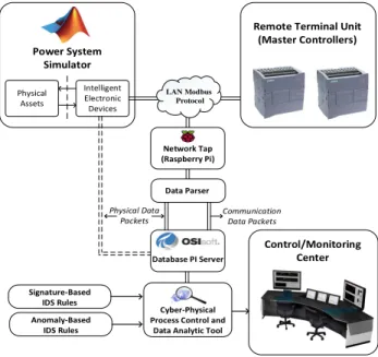
In this section, we provide details about the real-time testbed environment that we developed, using an integrated framework of tools for process management and cyber-physical security, and discuss about its capabilities. The testbed consists of a physical system modeled in the Simulink en-vironment, and real and simulated programmable logic con-trollers (PLCs) that generate real network traffic and ex-change packets based on industrial control protocols, in our case the Modbus protocol [26]. In addition, our testbed in-cludes a network tap to capture network traffic exchanged between the various controllers, and a data management for data processing and storing. On top of the underlying testbed deployment, we implemented a NIDS interface that processes streaming data in the historian, continuously mon-itors the network traffic, applies a set of cyber-physical se-curity policies, in the form of checks, to decide about abnor-malities or attacks, and visualizes the results of the checks. Finally, cyber-physical analytics related to the state of the system, including physical devices and communication links among them, are displayed to the network operators in a simple and descriptive manner.
Taking into consideration the complexity of setting up our testbed, it can be configured and monitored from two
ma-chines running a different operating system because of lim-itations on the required operating system by some software elements included in our testbed environment. However, this fact could be easily overcome by using virtual machines that run different operating systems instead of desktop machines. Once the required software and hardware is deployed, there is a specific hierarchy on the execution turn of each element that should be followed in order to achieve synchronization among them. The synchronization is trivial following a com-mon logic, e.g., we should first initiate the execution of the physical system in order to generate data and be able to save them in the data historian.
We also note that our testbed environment supports re-peatability in order to obtain the same or statistically similar results. A researcher/tester could easily reproduce a previ-ously tested experiment since the initial state and set up of the controlled environment is fixed at the start of each sim-ulation and is a user-defined choice. In addition, as previ-ously mentioned, the network traffic exchanged between the various controllers is saved in the data management, which makes it easy to the researcher/tester to directly apply the NIDS rules to the saved data, without re-creating a physi-cal environment, and obtain statistiphysi-cally similar results. In addition, we believe that it is feasible, for several users to simultaneously perform experiments because it is possible to run several instances of the same software tool, or even par-allel simulations on a software, such as the Matlab/Simulink environment. However, since we did not investigate this ca-pability, it would increase the complexity of the overall set up because it would require partition of the data historian in order to differentiate the network traffic related to each experiment. The general architecture of our testbed environ-ment, which is made up of a number of distinct elements, including the NIDS, a fully description of which is out of scope of this work, is shown in Figure 1.
Network Tap (Raspberry Pi) Physical Assets Intelligent Electronic Devices
Remote Terminal Unit (Master Controllers) Power System Simulator LAN Modbus Protocol Cyber-Physical Process Control and
Data Analytic Tool Signature-Based IDS Rules Anomaly-Based IDS Rules Control/Monitoring Center Database PI Server Data Parser Physical Data
Packets Communication Data Packets
Figure 1: General Architecture of the Testbed.
3.1
Physical System
In the real world, power systems obey physical laws that are completely known, such as Kirchhoff’s and Ohm’s laws.
The voltage and currents power carriers are narrowband sig-nals centered around 50 or 60Hz. The steady state behavior can be easily simulated through algebraic equations and the transient behavior is characterized by ordinary differential equations (ODEs) [4].
The Matlab/Simulink environment provides a number of libraries that assist in representing and simulating the math-ematical model which characterizes the behavior of physi-cal sub-systems on the grid, such as transformers, capaci-tor banks, electric mocapaci-tors, etc.. Graphical block diagrams that simulate the physical laws can be interconnected to simulate the behavior of dynamic systems that have several components. For that reason, the Matlab/Simulink environ-ment is widely used for modeling dynamic systems. There are two very useful features of Simulink that we leveraged in our testbed: 1) its ability to interact with actual micro-controllers and 2) simulating the behavior of hybrid systems, thereby reproducing the interaction between the dynamic system and simulated micro-controllers that are placed on the model and run specific rules.
In addition, it is important to note that the simulated micro-controllers can interact with real micro-controllers and send actual network packets out, a key feature that has made our testbed possible. Even though it is possible to develop algorithms that run on micro-controllers supporting analog and digital connectivity, and serial communications in or-der to control physical systems, we chose to make use of actual PLCs that support industrial control protocols and we could generate real network traffic. Finally, even though, the type and size of the physical system were not, at least initially, one of our mainly concerns, we note that the Mat-lab/Simulink environment could be used to model a wide range of physical systems, including large scale electrical grids such as IEEE 14-bus or 30-bus systems.
Specifically, in our work, we developed a Simulink model for a physical system controlled and protected by a real, master programmable logic controller either directly, or by interaction via real Modbus communications with one or more simulated field devices placed on the Simulink model. This architecture is typical in Industrial Control and re-flects the hierarchy of Supervisory Control and Data Acqui-sition (SCADA) systems in which Master Controllers (Re-mote Terminal Units (RTUs)) interact with several field de-vices (Intelligent Electronic Dede-vices (IEDs)) to carry out one or more protective missions. Sensor and detector outputs are indicate analog, (e.g., current and voltage magnitude or phase) or digital measurements, e.g., state of a switch. These values are given as input to the next level, which is responsi-ble for embedding them in Modbus packets and exchanging them with the appropriate controllers.
In our tests we assumed that this part is performed by the slave controllers (the IEDs or field devices) that were simulated, when considering a master/slave communication model. Moreover, a number of actuator inputs are assigned to the simulation block and connected either to the simu-lated IED or directly to the master controller’s outputs that interact directly with the physical processes in blocks of the Simulink physical system that we envision, and are directly controlled by the Master (e.g., the RTU). We refer to this type of interaction either as analog or digital feedback, based on the nature of the output signal, since these signals indi-cate the result of the control mechanism implemented in the master controller.
3.2
Control
Based on the master/slave communication model, the mas-ter controller implements the protection and control mech-anisms related to the physical system implemented through the Simulink environment. For experimental purposes, we implemented an emulation of a master controller in ladder logic using a real PLC. In addition, in order to create a mod-ular version of our testbed environment, we also created a simulation of the control and protection mechanism, that was implemented inCprogramming language. We want to note, that our approach can be applied to a variety of dif-ferent types of control and protection mechanisms for CPSs, such as power systems, and can be implemented either by emulation or simulation of the PLCs. In the next two subsec-tions, we provide further details about the implementation of both emulated and simulated controllers.
3.2.1
Emulation using a real PLC
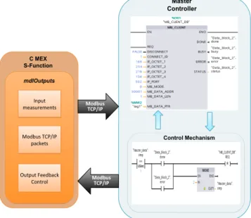
Our implementation of emulation using a real PLC uses a Siemens SIMATIC S7-1200 PLC that acts as the master controller and performs the protection function and control mechanism of the physical process. This PLC supports both Ethernet and TCP/IP-based communication protocols, such as the Modbus, allowing communication either as a Mod-bus client (master) or server (slave). We implemented the control mechanism in Ladder logic using the SIMATIC Soft-ware Step 7 Basic. Figure 2 shows the general concept of the communication between emulated and simulated PLCs, and the function that we used. The function block that we used is implemented in Ladder logic and is included in the SIEMENS S7-1200 communication library, as well as the communication between the TIA Portal software and the S-function block. Master Controller C MEX S-Function Modbus TCP/IP Modbus TCP/IP Control Mechanism mdlOutputs Modbus TCP/IP packets Output Feedback Control Input measurements
Figure 2: Communication between a simulated slave PLC and an emulated master PLC.
Specifically, we consider a master controller that is re-sponsible for initiating a connection, and exchanges data with the simulated slave controller. The master controller polls the slave controller in order to acquire the value of the input measurements obtained by the related sensors, such
as the value of the current that flows on a power transmis-sion line. Then, the protection control algorithm is executed and, based on the result, the master controller sends “write” queries to the slave controller indicating which control ac-tion should be performed, such as activating one or more circuit breakers.
3.2.2
Simulation of a PLC using libmodbus
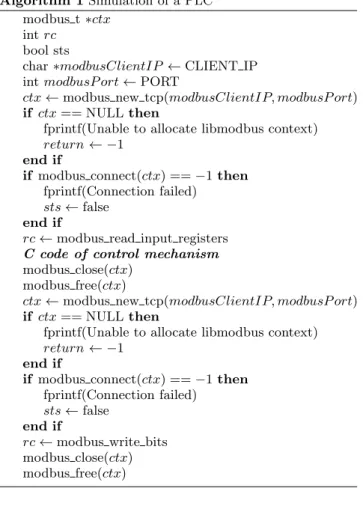
The simulation of the master controller was implemented inC, and uses the Modbus protocol library libmodbus [13] in order to allow communication through the Modbus in-dustrial control protocol. The specific implementation con-stitutes a replica of the implementation of the protection and control mechanism in ladder logic using the real PLC. The use of a simulated master controller is a more flexi-ble route when no access to real devices is possiflexi-ble, and it also provides substantially greater freedom when choosing the industrial control protocol that will be used to establish communication and exchange data within the network of the controllers. However, even though simulating the soft-ware components has always been assumed to be a more efficient way, it could fail to operate in the same way as real devices do under failures of hardware components or com-puter systems. Figure 3 shows the communication between the simulated PLC written inCusing thelibmodbuslibrary and the S-function block.
Master Controller Create Modbus TCP Connec1on Modbus TCP/IP read request Modbus TCP/IP read response Control mechanism Close Modbus TCP Connec1on Modbus TCP/IP write request Modbus TCP/IP write response C MEX S-‐Func3on mdlOutputs Modbus TCP/IP packets Output Feedback Control Input measurements If prev_r eq == re ad ne xt_r eq = w rite If co ntr ol _m ec h == do ne re le as e co nn ec 1o n Modbus TCP/IP Modbus TCP/IP
Figure 3: Communication between the Mat-lab/Simulink environment and a simulated PLC.
Similarly to the procedure described above in the descrip-tion of the emuladescrip-tion, the master controller establishes a connection with the slave controller and dispatches “read” requests in order to obtain the value of physical measure-ments. Then, the simulated master controllers perform the protection control algorithm related to the protection of the physical system, and dispatches the appropriate queries in-dicating the result of the protection mechanism via control actions. Also, in between the two different types of requests, the master controllers releases the connection. Algorithm 1 shows the generalized sequence of the primary functions ex-ecuted in theCcode our case study, where we assume that the master controller receives analog values as inputs and re-turns digital values. However, theCcode can be customized for different cases based on the requirements of the applica-tion, as well as the control mechanism, the code of which is
not shown in Algorithm 1 since it is related to the chosen protection and control mechanism.
Algorithm 1Simulation of a PLC modbus t∗ctx
int rc
bool sts
char∗modbusClientIP←CLIENT IP
int modbusP ort←PORT
ctx←modbus new tcp(modbusClientIP, modbusP ort) if ctx== NULLthen
fprintf(Unable to allocate libmodbus context)
return← −1 end if
if modbus connect(ctx) ==−1then fprintf(Connection failed)
sts←false end if
rc←modbus read input registers
C code of control mechanism
modbus close(ctx) modbus free(ctx)
ctx←modbus new tcp(modbusClientIP, modbusP ort) if ctx== NULLthen
fprintf(Unable to allocate libmodbus context)
return← −1 end if
if modbus connect(ctx) ==−1then fprintf(Connection failed)
sts←false end if
rc←modbus write bits modbus close(ctx) modbus free(ctx)
3.3
Communication
The part of the communication between the physical model implemented using the Matlab/Simulink environment and actual controllers constituted one of the challenges that we had to overcome during the development of our testbed. Among the many capabilities that Matlab supports, we de-cided to use the option of direct communication under a client/server architecture, including interfaces to support TCP and UDP protocols. Our vision was to develop a testbed that could support various industrial control pro-tocols that run over TCP or UDP, such as DNP3 and IEC 61850, by either leveraging existing libraries, an option that is not difficult to apply, or by “formatting” the packets based on the appropriate packet frame format. In this way, a po-tential user could easily modify our initial implementation to adjust the communication type based on the requirements of the current controllers or preferences among the different industrial control protocols.
Our real-time testbed environment allows us to establish communication between a simulated physical process and a real or a simulated PLC through an Ethernet interface that sends information via the Modbus industrial control pro-tocol. While many cyber-physical processes rely on more advanced options, the choice of Modbus for our experimen-tal validation is dictated by practical convenience: PLCs are inexpensive and a variety of software tools and libraries ex-ist to communicate with them. However, the ideas that we
present in this paper are applicable to many of the applica-tion layer protocols used in industrial and control systems. We do note however, that different methods would need to be employed if the network communications are encrypted. Specifically, we leveraged the capabilities of Matlab that supports TCP/IP communication in order to enable commu-nication and transfer data over the Modbus industrial con-trol protocol. We developed an S-function block that was implemented in Cand which uses the open source Modbus protocol librarylibmodbusin order to simulate the commu-nication behavior of a controller on a linux operating sys-tem. The S-function code is compiled using the Matlab mex compiler [16], which also creates a dynamically-loadable ex-ecutable used by the Simulink model. The same approach could be used to allow communication through other indus-trial control protocols by including the S-function code for the appropriate protocol libraries instead of the Modbus pro-tocol library.
The S-function block receives as inputs the outputs of the physical process implemented using the Simulink environ-ment, and allows communication with a second PLC. The sensors and detectors included in the dynamic model provide the S-function block with the appropriate physical measure-ments, which are used in the next level in order to check the consistency of the physical model. Then, the S-function block is responsible for formulating packets that include the input measurements, and dispatches the Modbus packets to the master controller whenever a “read” command query is received. The S-function block also performs the feedback control actions specified in a “write” query, which the master controller sends after the protection and control mechanisms are executed. In addition, the time of each measurement sample is also given as an input to the S-function block in order to process a specific number of samples and calculate an estimate of the specific measured variable within a given time frame. The S-function begins by including and defining the necessary libraries, headers, and variables, including the following:
- libmodbuslibrary
- width of analog input/outputs - width of digital input/output ports - client’s IP address
- sampling frequency.
Then, the S-function method mdlInitializeSizes is exe-cuted to set up the characteristics of the S-function block:
- assignment of analog inputs/outputs to specific ports - assignment of digital inputs/outputs to specific ports - data types of analog inputs/outputs
- data types of digital inputs/outputs.
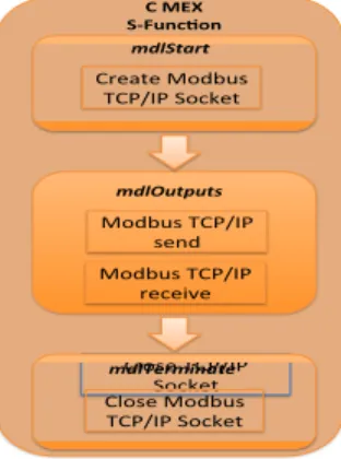
The S-function methodmdlInitializeSampleTimesindicates the sample rates, where in our case the value CONTINU-OUS SAMPLE TIME is used for continuous sample rate, and themdlStartmethod is executed only once for initializa-tion purposes. In the next step, the S-funcinitializa-tionmdlOutputs
function method is executed and is responsible for acquir-ing the measurements from the Simulink model, formulatacquir-ing the Modbus packets, and computing the output signals of the S-function block that corresponds to the feedback of the control mechanism. The S-function function method
mdl-Terminateis called at the end of the code to perform actions
such as emptying memory. Figure 4 shows the sequence of the functions executed within the S-function block.
C"MEX" S'Func,on" Close&TCP/IP& Socket& & & & & & & & & & & & & & & & & & mdlStart( mdlOutputs( mdlTerminate( Modbus&TCP/IP& send& Modbus&TCP/IP& receive& Create&Modbus& TCP/IP&Socket& Close&Modbus& TCP/IP&Socket&
Figure 4: Methods executed in the S-function block.
3.4
Network Tap
The purpose of the network tap is to capture the network traffic exchanged between the controllers that are embedded in the Matlab/Simulink hybrid physical system simulation, and the real controller (PLC) that implements a protection mechanism and interacts with the physical model. We im-plemented the specific element using a Raspberry Pi and an Ethernet hub where all the physical PLC devices are con-nected. The choice of the Raspberry Pi was dictated by to factors: 1) low-cost hardware; 2) supports two separate net-work interfaces that allowed us to split connections among control devices and the data management.
More in detail, in this stage, a Python script using the libcap/pcapy library runs on the Raspberry Pi in order to capture the network traffic. The libcap/pcapy library is an open source tool which can be easily used on several plat-forms. The captured network traffic is then reported via a second Ethernet card to our data historian and processed so that it can be visualized for the operator. The idea is that the industrial control network and the network aimed at monitoring the traffic should be isolated, reducing poten-tial attack vectors. Also our network tap cannot be used to access or attack the physical devices, as firewall rules do not allow any outward traffic on the Ethernet card doing the packet capture. A possible attack could occur by gain-ing root access on the Raspberry Pi, however, by closgain-ing all incoming ports and discarding any incoming traffic but acknowledgements on the data management interface, this threat could be restricted to a case that requires physical access to the device.
3.5
Data Management
The data management part consists of the OSIsoft [21] PI System, one of the industry-leading data management sys-tems. We chose to use the PI System because it is often al-ready in place in industrial environments, particularly power utilities. Second, the PI System provides a complete frame-work for data management and archiving. In our setup the PI Server receives data from the network tap and archives it in the form of pre-defined tags. The PI Sever can be either queried online or offline by the NIDS, which implements a set of security policies and is aware of the physical laws and communication rules that designate normal behavior of the
cyber-physical system. Specifically, the PI Server performs two actions: 1) stores data from the network tap; 2) retrieves stored data when queried by the NIDS.
One of the challenges arising when considering data his-torians in CPSs is data volume. A CPS typically includes a large number of sensors that generate data every few min-utes; these are the records stored in data historians for pro-cessing reasons. The process data historian stores data of fixed size in individual fields, in our case in the form of tags, the amount of which after a certain period and depending on memory capabilities of the various databases could cause memory overflow since the stored data exceed the capac-ity of the database system. Therefore, conventional data historians integrated to testbed environments that handle a large amount of data need to consider additional solutions to address issues relating to high data volume, e.g., using com-pression, or, as in our case, periodically deleting old data.
The implementation of the above mentioned capabilities is a combination of C++and Python programming languages. Under the phase where we need to read data from the net-work tap, a Python script is responsible for processing the captured data, and, then, “forward” the processed data to the data historian. As Python does not have a direct sup-port for communication with the PI Server we are usingC++
program as middleware. More specifically, the execution of the steps during this phase for each packet is as follows:
1. Python script accesses the C++ script, and either es-tablishes connection with the network tap (real time) or recorded files (offline). Timestamps are extracted from original capture time.
2. Network packets are splitted based on the various header fields; only well-formed packets are processed.
3. Filter for Modbus packets (TCP port 502), and classify packets based on their type, e.g., query or response, based on their port (source or destination).
4. Extract the fields corresponding to specific tags: (a) plc source ip and plc destination ip
(b) plc transport identify and plc protocol identify (c) plc length modbus
(d) plc unit identifier (e) plc function code
5. Based on the type of packet and the command function code, decode the remaining datastream in the form of tags:
(a) plc reference number
(b) plc bit count and plc byte count (c) plc payload
(d) plc query or response
6. In cases where specific fields are not included in the packet frame under processing, assign “-1” to corre-sponding tags.
As soon as the data processing is completed, the next phase is to store data to the PI Server in the form of tags. TheC++script is now responsible for executing the following procedure for each field in a packet:
1. Create a socket to connect to the Python script, and connect to PI Server.
2. Receive data and timestamp form Python script in the form of tags, acknowledge each received tag; order of
arguments defines which tag to write at each time. Individual acknowlegements for each item ensure de-livery and ensure that the socket traffic is not uninten-tionally combined.
Having followed the above described procedures, the PI Server keeps archives in the form of tags related to the network traffic captured by the network tap. Now, we consider the phase where our NIDS wants to retrieve data stored in the PI Server in order to execute the set of cyber-physical secu-rity policies. Based on the fact that the PI Server follows a “pull” architecture, we need to query the server in order to retrieve the stored samples. In our implementation, we chose to query the server every 10ms, which based on our observations constitutes a good compromise between delay and overhead. The NIDS is implemented in Python scripts, which should connect to the C++ script that is responsible for querying the PI Server and retrieving stored data. Here, we only mention the steps followed by the NIDS in order to gain data, since a description of the security policies in the NIDS is out of the scope of this paper.
1. Python script connects toC++script at a given IP port, and sends read Tag cmd to theC++script.
2. Once an answer is received, send an acknowledgment, wait for a “req done”, and proceed to the next tag. On the data management side, the C++ script follows a number of steps in order to connect to the PI Server, and query it for data requested by the NIDS:
1. Open a socket with Python script, and connect to PI Server.
2. Once a Python script request is received, query the PI Server for the specified tag initial timestamp and number of samples that the script requested.
3. Check whether PI Server returned the right amount of samples. In case there are not enough samples avail-able, retry.
4. Check if timestamp is valid.
5. Send values and timestamps to Python script, and “req done” to Python script once the request is completed. Back to the big data problem, as we archive the complete set of network traffic in our system, we are capturing large quantities of data. While our scenario was small and limited in time we notice that there is the additional need to delete obsolete data from the archive, as otherwise network traffic will rapidly fill the available storage. One might mark data as obsolete after a certain amount of time to allow at least some backlogging and further investigation after an alert from our system. In the case of the PI Server that we used in our testbed, PI Server includes a configuration file where it is possible to globally set the option to delete pi data after a predefined number of GB. However, this is highly dependent on the environment in which the system is deployed, and should be addressed by the consumer.
3.6
Network Intrusion Detection System
The top level of our testbed environment includes a NIDS that implements a “hybrid” set of specification-based and anomaly-based IDS rules by blending common network com-munication policies with physical laws and limits that des-ignate the expected operation of the physical system. How-ever, the implementation of the hybrid control NIDS,
cluding development of the cyber-physical security rules in-cluded in the NIDS, and its performance, is out of scope of this paper and is described further elsewhere [11, 22, 18].
However, we do note that in our testbed deployment, the NIDS was implemented using Python scripts and is related to case studies of specific physical systems that we chose to evaluate its performance. Therefore, we note that the NIDS in our testbed environment can be customized based on the requirements and physical constraints of the physical sys-tem, and fully integrated to the overall testbed environment. Based on our observations during the set of experiments that we implemented, we believe that some difficulties may occur in cases where a complete NIDS framework is chosen instead of our version of implementing a set of intrusion detection rules in Python scripts. Network monitoring frameworks can be used to develop a NIDS but typically they make use of the network traffic in a direct way, i.e., by initially capturing the network traffic and processing them to extract necessary fields. In our case, our Python script queries the data his-torian based on the pi tags and makes direct use of them without further processing. As result, in order to be able to use a network monitoring framework to built a NIDS, it should be modified to accept already processed fields of the network traffic instead of whole network packets.
3.7
Cyber-Physical Visualization & Analytics
The final part of our testbed environment is the visual-ization of information in a form that is relatively easy to understand while still providing sufficient detail about re-sults of cyber-physical checks performed by the NIDS to be actionable. Hence, our aim was to provide to the operators or administrators of the physical system with a complete pic-ture that includes a description of the cyber-physical state of the system. The visualization part, which is described more in detail later in Section 4, includes information concerning the following physical and cyber aspects:
1. Master controllers, and their IP addresses
2. Slave controllers that correspond to specific physical devices, e.g., power transformers, and the protection schemes protecting them
3. Network communication links between the various con-trollers
4. Values of physical quantities, e.g., current, voltage, etc., and physical devices, e.g., circuit breakers, as well. 5. Results of the checks performed in the NIDS
6. Statistical information when considering anomaly de-tection
7. Alerts in cases of abnormalities or attacks.
The capabilities mentioned above provide a small set of fea-tures that our visualization software could support. De-pending on the physical system, the security policies imple-mented in the NIDS, and the physical or network values that one chooses to monitor or display, we believe that it can be easily extended in order to include more information. In our case, we implemented a set of features which we believe that could help CPS administrators understand abnormalities or attacks in a descriptive way.
4.
TESTBED EXPERIMENTATION
To evaluate our real-time testbed, we focused on the oper-ation of a power transformer on a transmission line that was
implemented in the Simulink simulation environment, simi-larly to that mentioned in the previously published work [11]. In this section, we focus on the cyber-physical analytics that are the result of the HC-NIDS [11], to help provide a visu-alization of the cyber-physical state for an operator.
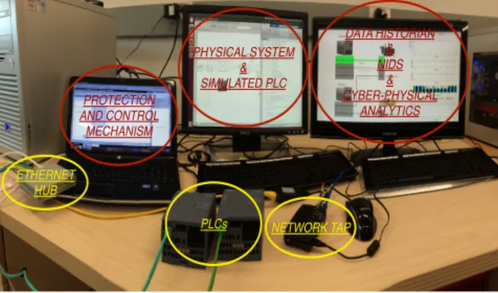
PHYSICAL SYSTEM & SIMULATED PLC DATA HISTORIAN & NIDS & CYBER-PHYSICAL ANALYTICS PROTECTION AND CONTROL MECHANISM ETHERNET HUB PLCs NETWORK TAP
Figure 5: Deployment of our testbed environment. We note that the purpose of this section is to highlight the way that the cyber-physical analytics are presented to the operators through the visualization of the system’s state, and not an evaluation of the performance of the HC-NIDS. Figure 5 shows an example deployment of our testbed en-vironment, including some of the actual hardware and soft-ware used in it, such as an ethernet hub, commercial PLCs, a network tap implemented using a Raspberry Pi, the Simulink model of the physical model, and the visualization of the cyber-physical analytics.
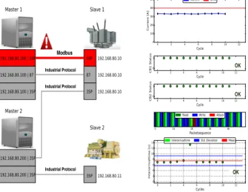
In our testbed environment, an operator is able to contin-uously see the state of the system via the representation of the status as it is reported by the HC-NIDS after the check of a set of intrusion detection rules implemented by the HC-NIDS. This set of intrusion detection rules is the result of the expected operation of the system by combining physical aspects (e.g., value of current, acceptable commands), and cyber aspects (e.g., acceptable IP addresses, protocol ID). Figure 6 shows the visualization of the cyber-physical ana-lytics that our real-time testbed environment makes avail-able to operators. More specifically, our visualization is di-vided into two parts:
1. Left part: represents the various physical devices un-der monitoring, including components of the physical system, protection mechanisms as device numbers as reported in the IEEE C37.2 standard, controllers, the network connections between them, and the various IP addresses related to each physical device.
2. Right part: represents values of physical quantities, e.g. transformer’s current, status of circuit breakers, and time gap between packets, which are all related to the cyber-physical rules included in the HC-NIDS. An operator monitoring the state of the system is shown the following: 1) an anomaly or attack was detected; 2) the corresponding rule that triggered the alert; 3) network traffic between which components was characterized as suspicious. In the case shown in Figure 6, the part of the system that is monitoring (highlighted with green color) corresponds to the scenario that we implemented of a power transformer’s
overcurrent protection, where the green color indicates that the system is under a normal state. In the next subsections, we present a number of experimental cases that correspond to different attack scenarios and how their detection is dis-played to the operators.
Modbus Industrial Protocol Industrial Protocol Industrial Protocol OK OK OK
Figure 6: Cyber-physical analytics in a normal state of the physical system under monitoring.
4.1
Packet sequence
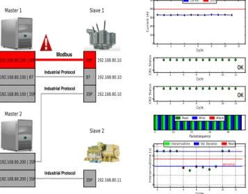
In this case, shown in Figures 7–8, we show the network traffic as a packet sequence where different colors represent different data items depending on source and destination devices, function codes, registers, sequence, and value range.
Modbus Industrial Protocol Industrial Protocol Industrial Protocol OK OK OK
Figure 7: Cyber-physical analytics for an abnormal-ity or attack on packet sequence.
The HC-NIDS identifies as normal traffic packets that appear in a “read query (dark green)-read response (light green)-write query (dark blue)-read query(light blue)” se-quence. Packet sequences that deviate from the desired expected packet sequence are considered by the HC-NIDS
as anomalies or attacks and are indicated with a red color. Since a query is, typically, followed by a response, in cases of an anomaly or attack we expect to observe one packet that is related to the query marked as red, and another one indi-cated again with red color about the corresponding response packet.
ATTACK
Figure 8: Packet sequence under normal and at-tacked state.
4.2
Status of circuit breakers
Based on our case study, the operator can monitor the status of the circuit breakers included in our physical system, in addition to the power transformer’s current. The right combination on their status indicates whether the protection mechanism is active or not, e.g., whether an overcurrent event was detected.
Modbus
Industrial Protocol Industrial Protocol
Industrial Protocol
OK
Figure 9: Cyber-physical analytics for an abnormal-ity or attack on the status of circuit breakers.
In cases where an attacker performs a malevolent action, e.g., by changing the status of the circuit breakers, when there is no need to do so based on the protection mechanism, the operator is shown a vizualization about the possible at-tack or abnormality, and can proceed to further actions, as we observe in Figures 9-10. More specifically, Figure 10 shows that in the case of an over-current event (left part) the protection mechanism was performed correctly by ac-tivated the circuit breakers, whereas in the case of a non over-current event (right part) the NIDS considered the ac-tivation of the circuit breakers as a possible attack or abnor-mality. In the last case where a possible attack is identified,
the status of the circuit breakers is displayed in red color, whereas green color indicate a normal status.
Figure 10: Status of circuit breakers under normal and attacked state.
4.3
Time gap between a cycle of packets
Here, we focus on the time gap between a cycle of pack-ets exchanged, where we define a cycle as the exchange of a “write” and “read” command, including their responses. In this case, network traffic is characterized as attack/anomaly based on statistical properties of arrival time of packets. The implementation of the specific rule in the HC-NIDS consti-tutes an improvement over the work presented in [11], by including anomaly-based intrusion detection rules. More specifically, we make use of the two-sided CUSUM tech-nique [8] in order to provide accurate time change detection of the time gap between subsequent cycles.
Modbus Industrial Protocol Industrial Protocol Industrial Protocol OK OK
Figure 11: Cyber-physical analytics under an abnor-mality or attack on the time gap within a cycle.
Figures 11-12 show that time differences between “read” command requests that exceed a pre-defined threshold, in-dicate an abnormality. The operator has a clear view of
sta-tistical information related to packet arrival time, such as the mean and the standard deviation. In cases where an ab-normality is detected, the time gap is displayed in red color, rather than green, which corresponds to a normal state.
Figure 12: Time gap between a cycle of packets un-der normal and abnormal state.
5.
CONCLUSIONS
Networked CPSs facilitate remote interaction, which makes them more convenient to access, but also makes them vul-nerable to a variety of cyber threats. To address this is-sue, CPSs should support cyber-physical security mecha-nisms, such as NIDSs, in order to alert control administra-tors about suspicious activities. Hence, there is a need to develop testbed environments that can be used to evaluate the effectiveness of potential security solutions. We believe that a testbed environment for cyber-physical security of CPSs should provide a realistic blend of hardware, software, and networking components. A realistic testbed environ-ment should include capabilities to analyze the complex re-lationships that are formed between the physical system, control mechanisms, and network-based security solutions.
In this paper, we discussed our testbed environment for validating a novel NIDS for industrial control processes by monitoring actual network traffic among controllers that perform a number of control actions in a simulated phys-ical environment. More specifphys-ically, initially, we leveraged the capabilities of Matlab/Simulink simulation environment in simulating physical processes to create a real communi-cation between the simulated physical system and actual controllers through common industrial communication pro-tocols, such as Modbus. A network tap captures traffic that flows within the network of the simulated controller and the emulated controller that implements protection mechanisms. In addition, we make use of a widely-applied industrial data management system, the OSIsoft PI System, to store the captured network traffic in the form of predefined tags, as well as data reported by the simulated physical system. Then, we apply a novel NIDS, that retrieves the stored data, cross-checks the data, and evaluates the data for possible anomalies or attacks using both “cyber” and “physical” el-ements. Finally, our testbed environment includes visual-ization features for making available to the operators of the infrastructure cyber-physical analytics about the state of the
system based on results of the checks implemented in the set of intrusion detection rules.
6.
ACKNOWLEDGMENTS
This research was supported in part by the Director, Office of Science, and the Director, Office of Electricity Delivery and Energy Reliability, of the U.S. Department of Energy, under contract DE-AC02-05CH11231. It is also supported in part by the Department of Energy under Award Number DE-OE0000097 and by the National Science Foundation un-der Grant Number CCF-1018871. Any opinions, findings, conclusions, or recommendations expressed in this material are those of the authors and do not necessarily reflect those of the sponsors of this work.
7.
REFERENCES
[1] U. Adhikari, T. H. Morris, and S. Pan. A
Cyber-Physical Power System TestBed for Intrusion Detection Systems. InProc. of the PES General
Meeting|Conference & Exposition, July 2014.
[2] M. Buscher, A. Claassen, M. Kube, S. Lehnhoff, K. Piech, S. Rohjans, S. Scherfke, C. Steinbrink, J. Velasquez, F. Tempez, et al. Integrated Smart Grid Simulations for Generic Automation Architectures with RT-LAB and Mosaik. InProc. of the International Conference on Smart Grid
Communications, pages 194–199, Nov. 2014.
[3] B. Chen, K. L. Butler-Purry, A. Goulart, and D. Kundur. Implementing a Real-Time Cyber-Physical System Test Bed in RTDS and OPNET. InProc. of the North American Power
Symposium (NAPS), Sep. 2014.
[4] E. A. Coddington and N. Levinson.Theory of
Ordinary Differential Equations. Tata McGraw-Hill
Education, 1955.
[5] C. Davis, J. Tate, H. Okhravi, C. Grier, T. Overbye, and D. Nicol. SCADA Cyber Security Testbed Development. InProc. of the 38th North American
Power Symposium, pages 483–488, 2006.
[6] P. Fritzson, P. Aronsson, H. Lundvall, K. Nystr¨om, A. Pop, L. Saldamli, and D. Broman. The
OpenModelica Modeling, Simulation, and Development Environment. InProc. of the 46th Conference on Simulation and Modelling of the
Scandinavian Simulation Society, Oct. 2005.
[7] A. Giani, G. Karsai, T. Roosta, A. Shah, B. Sinopoli, and J. Wiley. A Testbed for Secure and Robust SCADA Systems.SIGBED Rev., 5(2):4:1–4:4, 2008. [8] P. Granjon. The cusum algorithm a small review.
http://chamilo2.grenet.fr/inp/courses/
ENSE3A35EMIAAZ0/document/change_detection.pdf.
[9] A. Hahn, A. Ashok, S. Sridhar, and M. Govindarasu. Cyber-Physical Security Testbeds: Architecture, Application, and Evaluation for Smart Grid.
Transactions on Smart Grid, vol. 4:847–855, 2013.
[10] G. Hemingway, H. Neema, H. Nine, J. Sztipanovits, and G. Karsai. Rapid Synthesis of High-level Architecture-based Heterogeneous Simulation: A Model-based Integration Approach.Simulation, 88(2):217–232, Feb. 2011.
[11] G. Koutsandria, V. Muthukumar, M. Parvania, S. Peisert, C. McParland, and A. Scaglione. A Hybrid
Network IDS for Protective Digital Relays in the Power Transmission Grid. InProc. of the International Conference on Smart Grid
Communications, pages 908–913, Nov. 2014.
[12] A. Kusiak.Computational Intelligence in Design and
Manufacturing. John Wiley & Sons, 2000.
[13] Libmodbus.http://libmodbus.org.
[14] M. Mallouhi, Y. Al-Nashif, D. Cox, T. Chadaga, and S. Hariri. A Testbed for Analyzing Security of SCADA Control Systems (TASSCS). InProc. of the
PES Innovative Smart Grid Technologies, Jan. 2011.
[15] J. Martins, C. Lima, H. Mart´ınez, and A. Grau. A Matlab/Simulink Framework for PLC Controlled Processes.Matlab-Modelling, Programming and
Simulations, 2010.
[16] MATLAB. Matlab mex compiler.http:
//www.mathworks.com/help/matlab/ref/mex.html.
[17] J. McHugh. Testing Intrusion Detection Systems: A Critique of the 1998 and 1999 DARPA Intrusion Detection System Evaluations as Performed by Lincoln Laboratory.Transactions on Information and
System Security, 3(4):262–294, Nov. 2000.
[18] C. McParland, S. Peisert, and A. Scaglione. Monitoring Security of Networked Control Systems: It’s the Physics.Security & Privacy, 12(6):32–39, Nov/Dec 2014.
[19] S. B. Morriss.Automated Manufacturing Systems:
Actuators, Controls, Sensors, and Robotics.
Glencoe/McGraw-Hill, 1994.
[20] H. Neema, J. Gohl, Z. Lattmann, J. Sztipanovits, G. Karsai, S. Neema, T. Bapty, J. Batteh,
H. Tummescheit, and C. Sureshkumar. Model-Based Integration Platform for FMI Co-Simulation and Heterogeneous Simulations of Cyber-Physical Systems.
InProc. of the 10th International Modelica
Conference, pages 10–12, 2014.
[21] OSIsoft.http://www.osisoft.com/.
[22] M. Parvania, G. Koutsandria, V. Muthukumary, S. Peisert, C. McParland, and A. Scaglione. Hybrid Control Network Intrusion Detection Systems for Automated Power Distribution Systems. InProc. of the 44th Annual IEEE/IFIP International Conference
on Dependable Systems and Networks (DSN), pages
774–779, 2014.
[23] R. M. Reddi and A. K. Srivastava. Real Time Test Bed Development for Power System Operation, Control and Cyber Security. InProc. of the North
American Power Symposium, pages 1–6, 2010.
[24] C. Siaterlis and B. Genge. Cyber-Physical Testbeds.
Communications of the ACM, 57(6):64–73, 2014.
[25] C. Siaterlis, B. Genge, and M. Hohenadel. EPIC: A Testbed for Scientifically Rigorous Cyber-Physical Security Experimentation.Transactions on Emerging
Topics in Computing, 1(2):319–330, 2013.
[26] A. Swales. Open Modbus/TCP Specification.
Schneider Electric, vol. 29, 1999.
[27] S. Tan, W.-Z. Song, Q. Dong, and L. Tong. Score: Smart-Grid Common Open Research Emulator. In
Proc. of the Third International Conference on Smart