Rahimi, S. and Mehrez, K. and Marrow, T. J. (2016) Effect of surface machining on intergranular stress corrosion cracking (IGSCC) in sensitised type 304 austenitic stainless steel. Corrosion Engineering Science and Technology. ISSN 1743-2782 ,
http://dx.doi.org/10.1080/1478422X.2015.1122295
This version is available at https://strathprints.strath.ac.uk/56440/
Strathprints is designed to allow users to access the research output of the University of Strathclyde. Unless otherwise explicitly stated on the manuscript, Copyright © and Moral Rights for the papers on this site are retained by the individual authors and/or other copyright owners. Please check the manuscript for details of any other licences that may have been applied. You may not engage in further distribution of the material for any profitmaking activities or any commercial gain. You may freely distribute both the url (https://strathprints.strath.ac.uk/) and the content of this paper for research or private study, educational, or not-for-profit purposes without prior permission or charge.
Any correspondence concerning this service should be sent to the Strathprints administrator: [email protected]
The Strathprints institutional repository (https://strathprints.strath.ac.uk) is a digital archive of University of Strathclyde research outputs. It has been developed to disseminate open access research outputs, expose data about those outputs, and enable the
Effect of Surface Machining on Intergranular Stress Corrosion
Cracking (IGSCC) in Sensitised Type 304 Austenitic Stainless Steel
S. Rahimi1*, K. Mehrez2, T. J. Marrow3*
1
Advanced Forming Research Centre (AFRC), University of Strathclyde, 85 Inchinnan Drive, Inchinnan, Renfrewshire, PA4 9LJ
2
Meldfield Limited, Devonport Royal Dockyard, Plymouth, UK
3
Department of Materials, University of Oxford, Parks Road, Oxford, OX1 3PH Corresponding author: [email protected] (Tel: 0141 534 5243)
Abstract
The effect of surface finish, applied stress and test duration on the developed populations of short crack nuclei has been studied for a thermally sensitised type-304 austenitic stainless steel, exposed to acidified potassium tetrathionate (K2S4O6) solution. The crack populations
can be quantified using extreme value statistics (Gumbel distribution) to obtain a
characteristic crack length. The surface finish has a significant impact on crack development; a roughly machined surface, obtained with a greater depth of cut, is most susceptible to intergranular failure. The characteristic crack length of the crack population increases with tensile stress and test duration. Residual stress can cause cracking in the absence of an applied stress.
Keywords: intergranular stress corrosion cracking (IGSCC), austenitic stainless steels, sensitisation, crack growth, residual stress, Gumbel distribution, machining 1 Introduction
Stainless steels are amongst the materials selected for engineering structures where both high temperature mechanical performance and corrosion resistance are required 1. In particular, the austenitic type 304 and 316 stainless steels are used in the cooling systems of light water nuclear reactors (LWR) where mechanical strength and durability at elevated temperatures coupled with corrosion resistance are important 2. Stainless steels owe their corrosion resistance to the presence of a thin protective oxide layer 3. However, this passive layer can be vulnerable to corrosion due to local changes in alloy chemistry, and intergranular corrosion (IGC) and intergranular stress corrosion cracking (IGSCC) are significant failure mechanisms in sensitised austenitic stainless steels that are subjected to stress (applied or residual) and exposed to oxidising corrosive environments 4. Thermal sensitisation occurs via the formation of chromium-rich carbides at grain boundaries; this results in chromium depletion in the neighbouring regions 5, 6. Sensitisation by fast neutron irradiation can also cause changes in grain boundary chemistry in addition to affecting the characteristics of plastic deformation 7. It is generally considered that stainless steels require a minimum concentration of 12 wt% chromium to achieve passivity in oxidising environments; the depleted regions along the grain boundaries thus become susceptible to IGC and IGSCC if
*
The work was performed at the University of Manchester in the Materials Performance Centre. The authors have since moved to new positions.
the chromium content falls sufficiently 5. The amount of local chromium depletion with sensitisation is affected by factors such as alloy chemistry and grain boundary structure, and its significance depends on the corrosive environment and degree of sensitisation 8.
Sensitisation and its assessment are described in more detail in the standard tests 9-11, and various advanced methods for the characterisation of corrosion resistance in sensitised steels have been developed 12-15.
Crack initiation is influenced by surface properties in many engineering applications. For instance, the fatigue resistance of austenitic stainless steels tends to be dominated by the level of surface residual stress 16; the magnitude and distribution of residual stress depend on machining parameters 17-19, with higher levels introduced by rough machining 20. Pre-existing surface flaws and corrosion pits are preferential sites for stress corrosion crack nucleation in austenitic stainless steels; these are also affected by surface finishing processes
21, 22
. Furthermore, the cold deformation of the machining process can cause a local strain-induced martensitic transformation in unstable austenitic stainless steels 23, and deformation-induced martensite has been observed to increase the susceptibility of austenitic stainless steel to stress corrosion cracking (SCC) in both high temperature water 24 and in chloride environments 25, 26. The complex effects of surface stress and surface roughness were illustrated in a recent study 27 of the stress corrosion crack behaviour of type 316 austenitic stainless steel, tested in an aggressive chloride environment.
Despite a general understanding of the mechanisms that control crack initiation,
quantitative prediction of the relationship between surface preparation and crack development is difficult due to the complexity of the problem. Cracking is a stochastic process, and it is therefore useful to examine crack populations rather than individual cracks. This study explores the effects of surface machining on the development of intergranular stress corrosion crack nuclei in a sensitised type 304 austenitic stainless steel. The performance of
as-machined surfaces in two different states is compared with a nominally stress-free electro-polished surface. Statistical evaluation, using Gumbel extreme value distributions, is applied to analyse the relative development of the populations of crack nuclei.
2 Experimental Procedure
2.1 Material
The material studied was a type 304 austenitic stainless steel with high carbon content in the form of rolled plate with 13 mm thickness, fabricated in accordance with ASTM specification A 240/A240M-06 28. The plate was mill annealed by the manufacturer at 1050°C followed by cooling with forced air. Table 1 reports its chemical composition, as provided by the supplier.
Table 1: Chemical composition of the type 304 austenitic stainless steel plate.
Element Fe Cr Ni C Mn P S Si N
[wt-%] Bal. 18.15 8.60 0.055 1.38 0.032 0.005 0.45 0.038
The material is from the same plate used in previous studies 29, 30, in which detailed metallography and microstructure analyses were reported, including the variation of grain size and the distribution of -ferrite through the thickness. The proof stress (Rp0.2%) and the
Ultimate Tensile Stress (UTS), provided by the manufacturer’s certification, are given in Table 2, together with the limits specified by the ASTM Standard 31. The measured proof
stress and ultimate tensile stress for this plate in the solution annealed condition are also provided in Table 2, and were obtained in a previous study 29.
Table 2: Mechanical properties of the stainless steel. (UTS = ultimate tensile strength, Rp0.2% = proof strength at 0.2% strain).
Specification Rp0.2% [MPa] UTS [MPa]
ASTM A 240 / A240M – 06* 205 515
Manufacturer (Mill annealed)** 375 635
Rahimi 29 (Solution Annealed) 214 658
*
Minimum Values
**Obtained from Manufacturer’s certification
Thirty rectangular blank strips with dimensions 250 mm × 31 mm ×13 mm (L× W× T) were cut from the as received plate, with the specimen length parallel to the rolling direction (RD). The strips were solution annealed at 1050 for 2 hours followed by air cooling to ambient temperature, and aged at 650 for 24 hours to produce a fully sensitised microstructure; a detailed analysis of the sensitisation behaviour of this plate has been reported previously 15, 32. Following heat treatment, all the strips were machined to their final dimensions of 240 mm × 30 mm × 7 mm (L× W× T). This was done by removing 1 mm of material in one rough machining step from one side, then a total of 5 mm from the other side in four rough steps of 1 mm each with two further fine steps of 0.5 mm. These surfaces are identified respectively as the ‘Rough’ machined and ‘Fine’ machined sides. The machining was conducted with a Hurco Hawk 30 milling machine using a 4-flute endmill of 10 mm diameter at a tangential cutting velocity of 1.67 ms-1, with copious coolant applied. For both 0.5 mm (fine) and 1 mm (rough) depth of cut, the machining was performed at a rate of 0.025 mm per tooth,
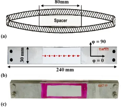
equivalent to a feed rate of 0.1 mm per revolution. Finally, a 6 mm hole was drilled through each corner of the strip to enable the use of stainless steel bolts for double-beam bend (DBB) testing of pairs of the strips (Figure 1a), following the ASTM G39-99 standard 33.
A previous study that used the same material found the microstructure was not quite
uniform across the plate thickness 30. Consequently, after the samples were machined to their final dimensions the average grain size was 80 ± 15 µm for the ‘Rough’ surface and 55 ± 10 µm for the ‘Fine’ surface. The grain size decreases towards the middle of the plate, where -ferrite bands were concentrated (maximum ~8% area fraction).
Figure 1: Sample geometry and double bend beam (DBB) specimen. (a) Schematic cross sectional view of DBB with exaggerated bending, (b) the top view shows positions of the XRD stress measurements, and (c) a photograph of one of the DBB specimens just after exposure to corrosive environment.
2.2 Surface Optimisation and Residual Stress Measurements
The residual stresses were measured by X-Ray Diffraction (XRD) using a PROTO-iXRD diffractometer and the sin2 method 34; the stresses were calculated from the strains of the {311} Bragg reflection, assuming elastic Young’s modulus E =190 GPa and Poisson’s ratio of v = 0.29. The measurements were in two perpendicular directions: longitudinal, along the length of the strip ( = 0˚, i.e. perpendicular to the direction of movement of the machining tool) and transverse, along its width ( = 90˚, i.e. parallel to the direction of movement of the machining tool).
Residual stress profile measurements on the machined surfaces were performed at a single point in the centre of the strip and then at progressively increasing depths via iterative
electro-polishing. Prior to electro-polishing, the sample was painted with lacquer, except for the electro-polishing window with dimensions of 25 × 20 mm. The electro-polishing used a solution of acetic acid (92 %wt.) and perchloric acid (8 % wt) at 45 V for up to 60 minutes. The cathode was type 304 stainless steel sheet, with approximate dimensions of 190 mm × 80 mm × 0.5 mm (L× W× T). At each step, the removed depth was measured using a micrometre and the longitudinal and transverse stresses were measured at the midpoint of the electro-polished area. The middle section of a fine-machined surface of a set of strips, over the central 80 mm long section, was also electro-polished for a period of one hour to remove approximately 150-200 µm; the objective was to remove the residual stresses induced by machining. Residual stress measurements were obtained before and after electro-polishing of the strips at 8 equally spaced points (~8 mm apart) located in the middle third of the strip and along its longitudinal centre line (Figure 1b).
2.3 Stress Corrosion Cracking Tests
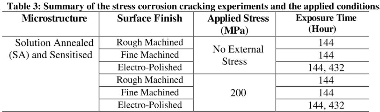
The stress corrosion cracking tests were done with samples that were loaded using the double bend beam (DBB) arrangement, and also with samples that were under no external applied load. Each DBB sample comprised two strips bent over a spacer with the ends held together by bolting (Figure 1); a spacer thickness of 3 mm was used to obtain a nominal flexural surface stress of 200 MPa, calculated using beam theory 33. This applied stress was verified by residual stress measurements that were obtained on an electro-polished surface, before and after loading of the strips 30. Exposure times of 144 and 432 hours were used. Table 3 summarises the surface finish conditions, applied stress and exposure times for all the tests conducted.
Table 3: Summary of the stress corrosion cracking experiments and the applied conditions. Microstructure Surface Finish Applied Stress
(MPa)
Exposure Time (Hour)
Solution Annealed (SA) and Sensitised
Rough Machined No External Stress 144 Fine Machined 144 Electro-Polished 144, 432 Rough Machined 200 144 Fine Machined 144 Electro-Polished 144, 432
The specimens were exposed to the test solution within cylindrical containers that had a capacity of approximately 2 litres. Four DBB assemblies were exposed to the test solution in each container simultaneously. The solution was a 0.1 M potassium tetrathionate (K2S4O6)
aqueous solution, with dilute sulphuric acid (H2SO4) added to obtain a pH of 2. At the end of
each test, the specimens were cleaned with tap water, and rinsed in deionised water and then ethanol before drying with hot air. The DBB specimens were then dismantled and all individual strips were stressed longitudinally using a tensile test machine (MTS – Alliance RT/100), monitored with a 20 mm gauge length extensometer to apply a tensile strain of 5% to 6%. The objective was to open any developed cracks to improve their visibility by optical microscopy 29, 30. After straining, the central region (80 mm length) was sectioned
longitudinally into three similarly sized pieces using a 0.5 mm thick diamond saw. The sections were mounted in cold resin, polished to mirror finish and observed by optical microscopy after electro-etching with a 10% aqueous solution of oxalic acid. The longest crack length within every interval of 2 mm along the tensile edge that had been exposed to the corrosive solution was recorded. Each strip therefore provided up to 80 measurements of crack length.
The obtained crack length data were evaluated against an assumed Gumbel distribution using an extreme value statistics methodology that describes the population through a single reduced parameter. The Gumbel distribution describes the longest likely crack in a given sample size, assuming a parent distribution of all cracks that has an exponentially decreasing tail function 35. This approach has been used previously for quantitative assessment of stress corrosion crack growth behaviour 30, 36.
The reduced parameter (Y) of the Gumbel distribution, as a function of measured crack length, was calculated.
where P = i/(n+1) is the empirical cumulative probability of the ith data point, n is the total number of crack measurements and i is the position in an ascending list of crack length 37. 3 Results
3.1 Surface Preparation
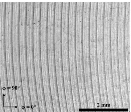
A stereo-optical micrograph of a typical surface in the fine machined condition is shown in Figure 2; the rough machined surface is visually similar due to the same feed rate being applied. The surface roughness was not measured, but using the same equipment and applying similar machining parameters on 316 austenitic stainless steel, i.e. at the same feed rate and tangential cutting velocity, with depths of cut of 0.4 mm (~‘fine’) and 1.4 mm (~‘rough’), the average surface roughness (Ra) was approximately 0.90 µm for the fine
surface and 0.50 µm for the rough surface 27. In some regions, bands were observed where overlapping of the machining marks was observed; these bands occur when the trailing tip of the tool makes occasional contact with previously cut areas. All the residual stress
measurements were conducted in regions where no overlapping marks were observed.
Figure 2: Typical fine machined surface, in the as-machined condition. The longitudinal = 0˚ direction is perpendicular to the machining profile and transverse = 90˚ direction is parallel to the machining profile.
The surface residual stress data, obtained at different positions along the middle section, are shown in Figure 3 for both the longitudinal ( = 0˚) and transverse ( = 90˚) directions of the fine and rough machined surfaces. The surface residual stress is tensile in both directions and above the material’s 0.2% proof stress, indicative of the plastic strain introduced. The
transverse residual stresses are similar for the fine and rough machined surfaces, while the longitudinal residual stress tends to be higher for the rough machined surface. The average longitudinal stress is lower than the transverse stress for both surfaces; 429±156 MPa
compared to 682±141 MPa for the rough machined; and 304±101 MPa compared to 715±118 MPa for the fine machined. It is noticeable, however, that there are local variations in
magnitude that are larger than the measurement uncertainty. The effects of electro-polishing to remove approximately 100-150 µm material from a fine machine surface are also
presented in Figure 3; the average stresses are negligible at -38±146 MPa and 15±154 MPa , in the longitudinal ( = 0˚) and transverse ( = 90˚) directions respectively.
Figure 3: Residual stresses measured on rough machined, fine machined and electro-polished surfaces, (a) longitudinal ( = 0˚) and (b) Transverse ( = 90˚). The electro-polishing removed approximately 100 to 150 µm from a fine machined surface.
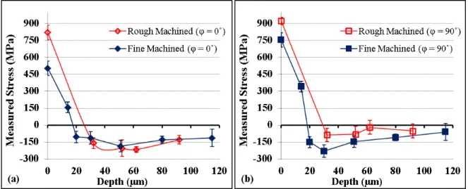
The variation of residual stress with depth is shown in Figure 4 for the fine and rough machined surfaces; the measurements are in both longitudinal ( = 0º) andtransverse ( = 90º) directions. Similar data are observed for both machined conditions. For the longitudinal direction a higher surface residual stress was measured for the rough surface (820 ± 54 MPa) compared to the fine surface (504 ± 61 MPa). Similarly, in the transverse direction a higher surface residual stress was also measured for the rough surface (921 ± 63 MPa) compared to the fine surface (753 ± 64 MPa). These differences are not those observed generally on average (i.e. Figure 3), but are within the range of localised variations that are observed. For both surfaces, the residual stress components become significantly compressive (~ -200 ± 70 MPa) over a distance of 40 µm from the surface, and diminish to ~ -130 ± 50 MPa for longitudinal and ~ -60 ± 55 MPa for transverse directions after 100 µm.
Figure 4: Residual stress profiles measured as a function of depth on both rough machined and fine machined surfaces; (a) in the longitudinal direction ( = 0°); and (b) in the transverse direction ( = 90°).
3.2 Effect of Surface Condition on IGC and IGSCC
Examples of specimen surfaces after testing and tensile straining are shown in Figure 5. Both samples were exposed for 144 hours under load, and the developed populations of cracks are aligned perpendicular to the applied bending stress. It is noticeable that the development of cracking is much less severe in the regions where overlapping machining marks are observed; these are indicated by a dotted yellow box.
Figure 5: Stereo-Microscopy optical images of the specimen surface following a test of 144 hours duration at 200 MPa; (a) rough machined, and (b) fine machined. Regions of overlapping machining tool marks are indicated by a dotted yellow box.
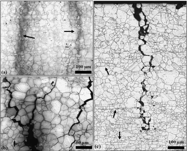
An optical microscopy image of the electro-polished surface after exposure to the test solution is shown in Figure 6a; the sample, which was exposed for 432 hours under load, has not yet been strained in tension. The grain boundary networks have been etched by the test environment, but cracking cannot be reliably identified. Tensile straining opened the cracks sufficiently to distinguish them from the etched, but non-cracked boundaries (Figure 6b). As with the machined surfaces, the cracks tend to develop perpendicular to the applied flexural stress. In cross-section (Figure 6c), the heterogeneity of grain size and the non-uniform distribution of delta ferrite are observed.
Figure 6: Crack development in an electro-polished sample, exposed to the test solution for 432 hours under load; (a) the exposed tensile surface before post-test tensile straining - the arrows point at features that may be intergranular cracks; (b) the exposed tensile surface after post-test tensile strain to open the cracks; (c) cross section of the same sample, after electro-etching - the arrows point at -ferrite bands. In each image the tensile stress is applied in the horizontal direction.
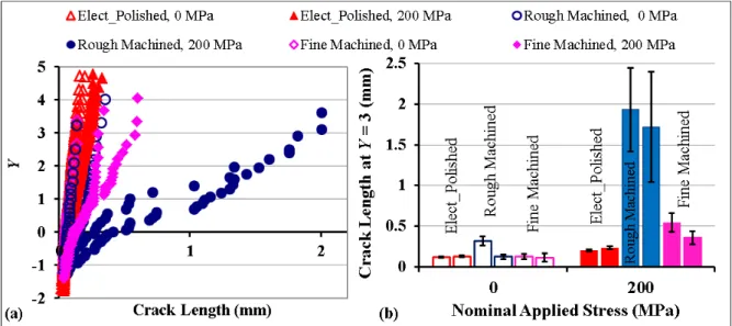
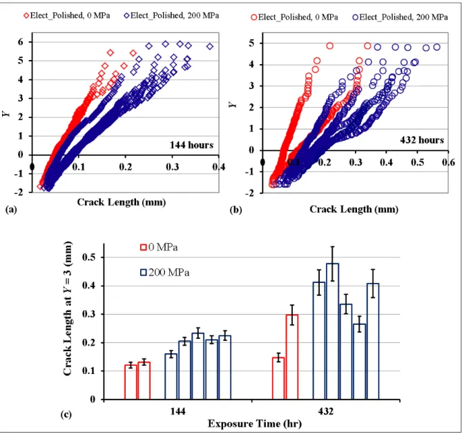
The crack population data, presented in Figure 7a for the tests with 144 hours duration, reveal the significant effects of surface finish and applied stress; the longest cracks tend to develop for the rough machined surface with an applied bending stress. The data, plotted as the reduced parameter Y as a function of crack length, are described well by the Gumbel distribution, indicating that the population of cracks has been appropriately sampled. For ease of comparison between datasets, the expected crack lengths at a single value of the reduced parameter Y (i.e. Y = 3) are summarised in Figure 7b. The expected crack length is obtained from the best fit to the Gumbel distribution; the error bars indicate the confidence interval of 95%. From Equation 1, the reduced parameter at Y=3 is the maximum crack length that would be observed with 95% probability within each assessment length of 2 mm along the sample surface; i.e. there is a 5% probability of finding a crack exceeding this size within the assessment length. Although there are some differences between identical samples tested simultaneously, this representation of the data shows clearly that the rough machined surface tends to develop longer cracks than the fine machined surface, with the shortest cracks in the electro-polished surface under similar testing conditions. These differences are accentuated with the application of tensile stress in bending. The same trends are found when examining other values of Y. The effect of exposure time is presented in Figure 8, which
shows deeper cracks develop with longer exposure time and also with applied tensile bending stress.
Figure 7: The effect of surface condition and applied stress for samples tested for 144 hours; (a) Gumbel probability for the crack distribution; (b) expected maximum crack length (at Y=3) from data in (a).
Figure 8: Effect of applied load and exposure time on the crack development; crack populations (a) after 144 hours; (b) after 432 hours; (c) Expected maximum crack lengths at Y=3, obtained using best fit to data in (a) and (b).
4 Discussion
As a direct result of the mechanical removal of material layers by cutting 38, machining processes generate type II residual stresses 39, 40 that are localised over a short distance below the surface of the material. The residual stresses reported in this work are typical of previous reports on machining induced stresses in stainless steels. Tensile surface stresses are
observed here (Figure 3), but the machining induced residual stresses at the surface can be tensile or compressive depending on the machining parameters, and generally become compressive below the surface 27, 41, 42.
Electro-polishing removes the microstructure that has been deformed by machining 42, and hence removes the cause of the type II residual stresses to provide an essentially stress-free surface (i.e. Figure 4). The uncertainty in stress measurement on the electro-polished surfaces was about 100 MPa; this is higher than obtained for the machined surfaces (Figure 3), but is typical for XRD in stainless steels 30, 41, particularly when considering the effect of coarse grains on the measurement uncertainty due to the reduced sampling population.
Intergranular corrosion in thermally sensitised stainless steels occurs due to the compositional heterogeneities in the vicinity of the grain boundaries that lead to the preferential dissolution of these regions 43. Cracking initiates at grain boundaries that have been damaged by
localised IGC and which are sufficiently loaded 44. The observation of cracking in the electro-polished samples without an applied load (Figure 7) indicates that there remain residual stresses in the microstructure that are sufficient to propagate intergranular stress corrosion cracking; these may be local type III residual stresses that arise from strain incompatibilities between grains of different orientation 38, 45.
Intergranular stress corrosion cracking occurs in all the machined samples, even in the absence of an applied load, and to a greater depth for the rough machined surface. In addition to the effect of applied load, differences in surface condition therefore act to encourage cracking (Figure 7). The significant tensile residual stresses at the machined surface provide a mechanical driving force for crack propagation 38, 45, sufficient to overcome the lower magnitude of sub-surface compressive residual stress. Although the average grain size is larger for the rough machined surface than the fine machined surface, a previous study found that grain size differences of this magnitude do not have a large effect on intergranular stress corrosion cracking resistance 30. In the tests reported here, due to the longitudinal tensile straining applied before evaluation of the crack population, the examined cracks are all aligned approximately perpendicular to the specimen’s longitudinal axis, and the
measured crack populations are therefore determined only by the longitudinal stresses that were present during the test. In the absence of an applied load, the surface longitudinal residual stresses are greatest for the rough machined specimens, although the transverse residual stresses are indeed higher and may be sufficient to develop cracks that were not observable in this work. For instance, in an investigation on the effect of machining on chloride stress corrosion cracking in austenitic stainless steel two distinctive types of cracks were observed due to the influence of the longitudinal and transverse stresses 27. The IGSCC crack lengths observed in this work generally increase with exposure time, and applied tensile stress, whether external or residual (Figure 7 and Figure 8). This observation is in agreement with previous work 30 that examined crack propagation from surfaces that were free of residual stress, and is also consistent with predictive models that consider the effects of applied stress magnitude and exposure time for intergranular crack development 36, 46, 47.
The observation that regions with overlapping machining marks are less susceptible to cracking (Figure 5) might be explained by differences in surface condition (stress,
microstructure and surface roughness), possibly caused by burnishing. Local measurements of residual stress, plastic strain and surface geometry, together with the statistical approach utilised here might be used to study this, and so obtain a more quantitative understanding of the effects of surface condition and applied loading on stress corrosion crack development.
5 Conclusion
The effects of surface preparation and applied loading can be quantified using extreme value statistics analysis of the intergranular stress corrosion crack populations.
Crack growth behaviour in sensitised 304 stainless steel is influenced significantly by both sample surface condition and mechanical applied stress. A roughly machined surface develops more significant cracking than a finely machined surface, even in the absence of an external applied load, due to local residual stresses introduced by machining.
6 Acknowledgement
This work was conducted in the Materials Performance Centre (MPC), School of Materials Science at the University of Manchester during the MSc study of K. Mehrez and PhD studies of S. Rahimi.
7 References
1. J. Davis: 'ASM Speciality Handbook: Stainless Steels'; 1994, Materials Park,
Ohio, ASM International.
2. D. Bodansky: 'Nuclear Energy: Principles, Practices and Prospects'; 2004, New
York, American Institute of Physics.
3. L. L. Shreir, R. A. Jarman, G. T. Burstein: 'Corrosion: Metal / Environment
Reactions'; 1994, Oxford, Butterworth-Heinemann.
4. S. M. Bruemmer, G. S. Was, Journal of Nuclear Materials, 1994, 216,
348-363.
5. N. Parvathavarthini: 'Sensitisation and Testing for Intergranular Corrosion', in
'Corrosion of Austenitic Stainless Steels. Mechanism, Mitigation and
Monitoring', (ed. H. S. Khatak, B. Raj ), 117 - 138; 2002, New Delhi, Narosa Publishing House.
6. S. M. Bruemmer, B. W. Arey, L. A. Charlot, Corrosion, 1992, 48(1), 42 - 49.
7. P. M. Scott, Corrosion, 2000, 56, 771–782.
8. R. K. Dayal, N. Parvathavarthini, B. Raj, International Materials Reviews,
2005, 50(3), 129 - 155.
9. British Standard, BS ISO 12732: Corrosion of metals and alloys -
Electrochemical potentiokinetic reactivation measurement using the double loop method (based on Cihal's method). 2006.
10. ASTM International, ASTM G108: Electrochemical Reactivation (EPR) for
Detecting Sensitisation of AISI Type 304 and 304L Stainless Steels. 1999.
11. ASTM International, ASTM E 112-96 e2: Standard test methods for
determining average grain size. 2004.
12. A. P. Majidi, Streicher, M. A., Corrosion, 1984, 40, 393 - 408.
13. M. Akashi, T. Kawamoto, F. Umemura, Corrosion Engineering, 1980, 29, 163
14. P. Muraleedharan, J. B. Gnanamoorthy, K. P. Rao, Corrosion, 1989, 45(2), 142 -149.
15. S. Rahimi, D.L. Engelberg, T.J. Marrow, Corrosion Science, 2011, 53(12),
4213-4222.
16. M. Kuroda, T. J. Marrow, Fatigue and Fracture of Engineering Materials and
Structures, 2007, 31, 1-18.
17. E. Brinksmeier, Residual Stresses Sci. Technol, 1987, 2, 839–847.
18. M. M. El-Khabeery, M. Fattouh, Int. J. Mach. Tools Manuf., 1989, 29, 391–
401.
19. P. Leskovar, J. Peklenik, Ann. CIR, 1981, P245–P248.
20. S. Al-Shahrani, T. J. Marrow: 'Effect of surface finish on fatigue of stainless
steels', 12th International Conference on Fracture (ICF-12), 2009, 861–870.
21. G. T. Burstein, P. C. Pistorius, Corrosion Science, 1995, 51, 380–385.
22. Y. Zuo, H. Wong, J. Xiong, Corrosion Science, 2002, 44, 25–35.
23. P. Marshal: 'Austenitic Stainless Steels, Microstructure and Mechanical
Properties'; 1984, Elsevier Applied Science.
24. D. R. Tice, S. Nouraei,K. J. Mottershead, J. W. Stairmand: 'Effects of cold
work and sensitization on stress corrosion crack propagation of austenitic stainless steels in PWR primary coolant conditions', 14th International Conference on Environmental Degradation of Materials in Nuclear Power
Systems Water Reactors, Virginia Beach, 2009, 158–171.
25. S. Ghosh, V. Kain, Journal of Nuclear Materials, 2010, 403, 62–67.
26. S. Ghosh, V. P. Singh Rana, V. Kain, V. Mittal,S. K. Baveja, Material Design,
2011, 32, 3823–3831.
27. K. N. Lyon, T. J. Marrow, S. B. Lyon, Journal of Materials Processing
Technology 2015, 218, 32–37.
28. V. Randle, D. Dingley, Scripta Metallurgica, 1989, 23, 1565-1570.
29. S. Rahimi: 'Behaviour of Short Intergranular Stress Corrosion Crack in
Austenitic Stainless Steel Type 304', PhD thesis, The University of Manchester, 2010.
30. S. Rahimi, T. J. Marrow, Journal of Fatigue and Fracture of Engineering
Materials and Structures (FFEMS), 2011, 35, 359-373.
31. ASTM International, ASTM A240/A 240M – 06: Standard Specification for
Chromium and Chromium-Nickel Stainless Steel Plate, Sheet and Strip for Pressure Vessels and for General Application. 2006.
32. S. Rahimi, D. L. Engelberg and T. J. Marrow, Journal of Materials Science and
Technology, 2010, 26(6), 670-675.
33. A. International, ASTM G39-99: Standard Prctice for Preparation and Use of
Bent-Beam Stress-Corrosion Test Specimens. 2000.
34. M. E. Fitzpatrick, A. T. Fry, P. Holdway, F. A. Kandil, J. Shackleton, L.
Suominen, NPL Measurement Good Practice Guide No. 52, 2005.
35. M. Kowaka: 'Introduction to life prediction of industrial plant materials:
application of the extreme value statistical method for corrosion analysis'; 1994, New York, Allerton Press.
36. T. J. Marrow, L. Babout, A. Jivkov, P. Wood, D. L. Engelberg, N. Stevens, P.
J. Withers, R. C. Newman, Journal of Nuclear Materials, 2006, 352(1-3),
62-74.
37. S. Beretta, C. Anderson, Y. Murakami, Acta Materialia, 2006, 54, 2277-2289.
38. P. J. Withers, H. K. Bhadeshia, Materials Science and Technology, 2001, 17,
366 - 375.
39. J. Prata Pina, M. Dias, J. L. Lebrun: 'Study of Residual Stresses and Cold
Working Generated by Machining of AISI H13 Steel', Second International Conference on Residual Stresses (ICRS2), 1989, Elsevier Applied Science, 690-695.
40. W. Bouzid Saï, N. Ben Salah, International Journal of Machine Tools and
Manufacture, 2001, 41, 443-450.
41. M. Kuroda, T. J. Marrow, Journal of Materials Processing Technology 2008,
203, 396-403.
42. S. Al Shahrani, T. J. Marrow, Key Engineering Materials, 2011, 465, 507 -
510.
43. R. W. Steahle: 'Bases for Predicting the Earliest Failures due to Stress
Corrosion Cracking ', in 'Chemistry and Electrochemistry of Corrosion and Stress Corrosion Cracking', (ed. R. H. Jones), K1 - K92; 2001, New Orleans, A symposium honouring the contribution of R. W. Steahle.
44. A. Stratulat, J. Duff, T. J. Marrow, Corrosion Science, 2014, 85, 428–435.
45. P. J. Withers, H. K. D. H. Bhadeshia, Materials Science and Technology, 2001,
17, 355 - 365.
46. A. P. Jivkov, N. P. C. Stevens, T. J. Marrow, Computational Materials Science,
2006, 38, 442-453.
47. A. Siddiq, S. Rahimi, Journal of Physics Conference Series, 2013, 451(1),