X.C. Arnoult et alii, Frattura ed Integrità Strutturale, 35 (2016) 509-522; DOI: 10.3221/IGF-ESIS.35.57
509
Short review: Potential impact of delamination cracks
on fracture toughness of structural materials
X.C. Arnoult, M. R
ů
ži
č
ková, K. Kunzová
Centrum Výzkumu Řež s. r. o., Husinec-Řež, Czech Republic Xavier.Arnoult@cvrez.cz
A. Materna
Czech Technical University in Prague, Faculty of Nuclear Sciences and Physical Engineering Prague, Czech Republic
ABSTRACT. The current energy policy envisages extended lifetime for the current nuclear power plants (GEN II NPP). This policy imposes a large research effort to understand the ageing of power plant components. In this goal, it is necessary to improve knowledge about safety, reliability and components’ integrity for more than forty years of operation. In Central and Eastern Europe, the majority of NPPs are VVER types, where some of the components are produced from austenitic steel 08Ch18N10T. Irradiated 08Ch18N10T may exhibit brittle behavior, namely delamination cracks are found in some cases on the fracture surface of irradiated 08Ch18N10T with elongated δ-ferrite. Delamination cracks have also been observed on the fracture surface of high-strength steels or aluminum-lithium alloys. This article presents a state-of-the art review to provide a detailed analysis of the influence of delamination cracks on the toughness of metal alloys. In general, the delamination cracks are present in metal alloys having a high texture and microstructure anisotropy. Three types of delamination cracks have been observed and are classified as crack arrester delamination, crack divider delamination and crack splitting delamination. The microscopy characterization, 3D fracture theories and computational studies explaining possible causes and effects of delamination cracks on the mechanical properties of metal alloys are presented.
KEYWORDS. Delamination cracks; Fracture Mechanics; Steels; Ferrite.
INTRODUCTION
elamination cracks, i.e. secondary cracks parallel to the rolling plane, have been observed on high strength steels [1-10], aluminum-lithium alloys [11-15], Ti-stabilized stainless steels [16, 17] and ultrafine-grained steels [18]. Different types of delamination cracks in combination with different orientations of the specimen direction had been identified [13, 19]. The delamination cracks have been classified (a) as crack divider, (b) crack arrester and (c) crack splitting as shown on the Figure 1.
In the last 4 decades, some researcher noticed the existence of delamination cracks and tried to understand the origins, mechanisms and consequences on the fracture toughness, impact toughness and tensile properties. Some delamination cracks are shown on the fracture surfaces of irradiated 08Ch18N10T with elongated δ-ferrite [16, 17], the 304 L and the 316 L after exposure in PWR [20] environments and degraded by hydrogen embrittlement [21].
X.C. Arnoult et alii, Frattura ed Integrità Strutturale, 35 (2016) 509-522; DOI: 10.3221/IGF-ESIS.35.57
510
As the current energy policy envisages an extended lifetime for the current Generation II nuclear power plants, large research effort must be devoted to understanding the ageing of power plant components, where delamination cracking is one of the possible ageing mechanisms. In this short review, the mechanism of delamination cracking is presented and open questions are identified in determining if the delamination cracks have negative or positive impact on the material toughness, which applies especially to the crack divider orientation.
(a) L-T and T-L orientation: crack
divider. (b)arrester. T-S and L-S orientation: crack (c)splitting. S-L and S-T orientation: crack
Figure 1: Terminology used to describe the various orientation of delamination cracks [13, 19].
INFLUENCE OF HEAT TREATMENT, TEST TEMPERATURE AND IRRADIATION
Tensile fracture surface
ramfitt and Marder [22] tested a very low-carbon steel (VLC steel) under tensile loading at room temperature to understand the influence of the finishing temperature of heat treatment (960°C - 150°C) on the fracture surface of this steel. After fracture, delamination cracks were observed in all transverse specimens from plates where the finishing temperatures were at 480°C and below. In the case of longitudinal specimens, delamination cracks occurred on specimens made from plates having a finishing temperature at 370°C and below. Thus finishing temperatures at least 260°C below the A1 temperature (i.e. the eutectoid temperature above which austenitic phase is formed) promoted the development of delamination cracks in the fracture process of the VLC steel. It was also observed that the number of delamination cracks increased with decreasing finishing temperature of heat treatment and delamination cracks were always orientated parallel to the rolling plane.
Baldi et Buzzichelli [23] investigated the influence of finishing temperature (cf. Table 1) and microstructure on seven different high-strength-low-alloy-steels (HSLA steels). They studied the tensile behavior of these steels as a function of finishing temperature and specimen orientation (0° and 90° relative to the rolling direction). The authors observed that on all studied HSLA steels, the fracture surface displayed longitudinal delamination cracks in both directions.
Code Heat Temperature, °C Rolling schedule temperature, °C Finishing thickness, mm Final Cooling
MC1 1150/2h 80% R.A. at < 750°C 700 12 Air
MC2 1150/2h 80% R.A. at < 750°C 700 12 Air
MC3 1150/2h 80% R.A. at < 800°C 750 12 Air
MC4 1150/2h 80% R.A. at < 750°C 700 12 Oil quench
F2A 1150/2h 80% R.A. at < 750°C 700 12 Air
C1B 1150/2h 80% R.A. at < 750°C 700 12 Air
M1 1150/2h 66% R.A. at < 900°C 750 12 Air
Table 1: Rolling and heat-treatment schedule [23].
Similarly, Yan et al [6] investigated the influence of tempering temperature on a HSLA steel. The 200°C, 400°C and 700°C tempered specimens exhibited a typical cup-and-cone tensile fracture (cf. Figure 2). There were no delamination cracks on the fracture surface. However, large and deep delamination cracks were observed on the fracture surfaces of tensile specimens tempered in the range between 500°C and 650°C (cf. Figure 9). The latter specimens did not have a typical cup-and-cone fracture shape, which indicates a low or very low ductility, and the fracture surfaces were divided in two
X.C. Arnoult et alii, Frattura ed Integrità Strutturale, 35 (2016) 509-522; DOI: 10.3221/IGF-ESIS.35.57
511
parts by the center. Guo 2002 [1] observed a similar phenomenon on CT specimens fabricated from API X70 steel. As Guo et al, Yan et al observed small delamination cracks close and parallel to the main delamination cracks.
Figure 2: SEM picture of a fracture observed on a 200°C-tempered tensile specimen [6].
Figure 3: SEM picture of fracture of 600°C tempered tensile specimen [6].
Tankoua et al [10] studied the influence of test temperature on the fracture surface of Arcelor pipeline steel. Specimen orientations were 0° and 90° according to the rolling direction. For both orientations, the authors observed three fracture modes in competition on notch tensile specimen. At 20°C, 100°C and -196°C the ductile fracture, ductile fracture with central delamination cracks and cleavage fracture were observed, respectively. This indicates a ductile-brittle-transition-temperature in the fracture behavior of this steel. In the case of -196°C, the cleavage fracture mode was accompanied by a small number of micro delamination cracks. Baldi and Buzzichelli [23] found central delamination cracks on a well-developed ductile fracture surface.
In the last decade, irradiated 08Ch18N10T specimens (chemically equivalent to A321) originating from the reactor vessel of the decommissioned VVER-440-Type 230 nuclear power plant located in Greifswald in northern Germany was evaluated by Hojna et al. [16, 17]. The authors observe a complex fracture surface after a tensile test at room temperature: ductile fracture zone and many different types of secondary cracks, among which delamination cracks were present [17].
X.C. Arnoult et alii, Frattura ed Integrità Strutturale, 35 (2016) 509-522; DOI: 10.3221/IGF-ESIS.35.57
512
Charpy impact toughness properties
The Charpy impact test may be used to evaluate the fracture energy at different temperatures, to characterize qualitatively the fracture mode (ductile or brittle facture) and to estimate the ductile-brittle-transition temperature (DBTT). This test is interesting to understand in which fracture mode the delamination cracks are displayed. All studies, cited in this section, used specimens with a V shape notch. Bramfitt and Marder [22] obtained four different Charpy curves at different heat treatment finishing temperature before being cooled down and the range of test temperature was from 24°C to -150°C. As heat treatment finishing temperature decreases, the upper shelf energy decreases from 160 J to 50 J and the DBTT was shifted to lower temperature and disappeared for specimen having a finishing temperature at 316°C. Charpy specimens manufactured from the plate finished at 960°C and tested at 24°C showed a fully ductile fracture surface. The same material tested at -18°C and -73°C showed a completely developed cleavage fracture.
For the Charpy specimens manufactured form the plate finished at 707°C that were tested at 24°C and -18°C, the fracture surface showed delamination cracks which were parallel to the rolling plane. At -18°C the number of delamination cracks was higher than at room temperature. When specimens were tested at -73°C, the fracture appearance was fully cleavage. The same phenomenon was observed for specimens manufactured from the plate finished at 538°C. However, the number of delamination cracks at equivalent test temperature was observed higher compared with the previous plate. For the specimens made from the plate having finishing temperature at 316°C, delamination occurred at all three temperatures, and the delamination has still occurred at -129°C where only 5% of the area was a cleavage fracture.
This study shows the influence of heat treatment and test temperature on the number of delamination cracks developed and their length present on the fracture plane, however, these qualitative results did not provide a clue on the role that the delamination cracks play in the fracture behavior of metal alloys. Baldi 1978 [23] and Song et al [18] observed a similar evolution of the number and length of delamination cracks related to the decrease of test temperature.
Figure 4: Effect of banding concentration on DBTT and upper shelf energy [24].
Shanmugan and Pathak [24] demonstrated the influence of the number of delamination cracks present on the fracture surface and how the Charpy toughness properties are influenced by these special cracks. They used a micro-alloyed steel and subjected it to a suitable heat treatment in order to implement a variation of ferrite bands in terms of density per mm. Figure 4 shows the effect of ferritic banding density present inside the microstructure on the Charpy toughness properties. During the Charpy test, the delamination crack density on the fracture surface corresponded approximately with the density of ferrite bands per mm. For temperatures higher than 10°C, a high number of ferrite bands led to a decrease of upper shelf energy and a shift of the DBTT to lower temperatures has been observed, as compared to the case of no ferrite bands present in the specimen. Contrarily, a low density of ferrite bands led to a higher upper shelf energy than in the case without ferrite bands. Similarly to Bramfitt and Marder [22], Shanmugan and Pathak [24] observed that delamination cracks seem to disappear with decreasing test temperature. According to them, this is due to the fact that at very low temperature, not enough time is given for delamination cracking process to take place. In this study, it was
X.C. Arnoult et alii, Frattura ed Integrità Strutturale, 35 (2016) 509-522; DOI: 10.3221/IGF-ESIS.35.57
513
shown that delamination cracks may have positive effect on the impact toughness properties if their number is relatively low. Fracture surface of specimens from plate of HSLA steels which underwent a tempering step [6] and were tested at room temperature did not display any delamination cracks, unlike those tested at -30°C (cf. Table 2 and Figure 5).
Tempering Temperature, °C CVN Impact Energy, J Delamination cracks
As-rolled 56 No
200 60 No
300 50 No
400 51 Small and Local
500 47 Large and Global
550 45 Large and Global
575 49 Large and Global
600 50 Large and Global
625 53 Large and Global
650 49 Large and Global
700 55 Small and Local
Table 2: Charpy Impact Toughness of tempered specimens and tested at -30°C [6].
Figure 5: SEM picture of fracture surface of Charpy specimens tempered at 200°C a), 400°C b), 500°C c), 600°C d) and tested at -30°C.
X.C. Arnoult et alii, Frattura ed Integrità Strutturale, 35 (2016) 509-522; DOI: 10.3221/IGF-ESIS.35.57
514
It was observed that at higher tempering temperatures delamination cracks increase both in number and in length, then decrease both in number and in length when the tempering temperature reaches 700°C. Yang et al [2] observed for API X70 pipeline steel a temperature dependence on the appearance of the fracture surface. At -60°C, specimen 10 mm thick and in T-L orientation showed a ductile fracture whereas at -20°C, authors observed some delamination cracks on the fracture surface. Joo et al [9] showed also an orientation dependence on the Charpy impact toughness. This could probably be explained by the development of delamination cracks during the fracture process. The API X80 [9] T-L and L-T oriented specimen had a ductile failure between 25°C and -60°C, with the presence of delamination cracks on fracture surface for temperatures from 20°C to 60°C, and cleavage failure mode without delamination cracks at 80°C and -100°C.
Figure 6: Charpy specimens’ orientation [9].
Figure 7: Charpy impact test as function of temperature a), as function of orientation b), fracture surface of L-T orientation of Charpy specimens broken at room temperature c), -60°C d), and -100°C e) [9]
X.C. Arnoult et alii, Frattura ed Integrità Strutturale, 35 (2016) 509-522; DOI: 10.3221/IGF-ESIS.35.57
515
For D-D orientation (cf. Figure 6), API X80 steel developed some delamination cracks only at -20°C and the impact energy was comparable for the other two orientations at the same temperature. For the other test temperatures (from -60°C to -100°C), cleavage fracture was the main failure mode for D-D specimen orientation (cf. Figure 7). For the authors, good resistance to impact of specimens with T-L and L-T orientation at ductile-brittle transition region is due to the capacity of delamination to take place during the failure process. Their assumption is reinforced by the fact that the impact energy dropped sharply below -60°C for the T-L and L-T oriented specimens and the only time when the D-D orientated specimens showed a similar magnitude of impact energy as T-L and L-T oriented specimens was when some delamination cracks were present during the failure process.
RELATIONSHIP BETWEEN METALLOGRAPHY AND DELAMINATION CRACKS
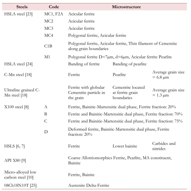
s described in the two previous sections, heat treatment and specimen orientation have a strong effect on the occurrence of delamination cracking as one of the fracture modes. It seems obvious that microstructure and texture of the studied steels is an important factor in this process. Different steels with various microstructure and texture were investigated.
Steels Code Microstructure
HSLA steel [23] MC1, F2A Acicular ferrite
MC2 Acicular ferrite
MC3 Acicular ferrite
MC4 Polygonal ferrite, Acicular ferrite
C1B Polygonal ferrite, Acicular ferrite, Thin filament of Cementite along grain boundaries
M1 Polygonal ferrite D=7µm, d=6µm, Acicular ferrite Pearlite
HSLA steel [24] Banding of ferrite Banding of pearlite
C-Mn steel [18] Ferrite Pearlite Average grain size = 6.8 µm
Ultrafine grained C-Mn steel [18]
Ferrite with globular Cementite particle in the grain
Cementite located at ferrite grain boundaries
Average grain size = 1.3 µm
X100 steel [8] A Ferrite, Bainitic-Martensitic dual phase, Ferrite fraction: 20%
B Ferrite and Bainitic-Martensitic dual phase, Ferrite fraction: 70%
C Ferrite and Bainitic-Martensitic dual phase, Ferrite fraction: 75%
D Deformed ferrite, Bainitic-Martensitic dual phase, Ferrite fraction: 20%
HSLS [6, 7] Ferrite Lower bainite Carbides and nitrides
API X80 [9] Coarse Allotriomorphics Ferrite, Pearlite, MA constituent, Bainite
Micro-alloyed low
carbon steel [10] Ferrite, Bainite
08Ch18N10T [25] Austenite Delta-Ferrite
Table 3: Different steels and their microstructure investigated for the understanding of delamination cracks.
X.C. Arnoult et alii, Frattura ed Integrità Strutturale, 35 (2016) 509-522; DOI: 10.3221/IGF-ESIS.35.57
516
As seen in Table 3, there are various kinds of steels where the delamination cracks could be one of the fracture modes. All these steels have a common characteristic, which is the presence of ferrite in the microstructure. Different authors performed metallography analyses to understand the origins and the mechanisms of the delamination cracking process. Typically, it has been concluded that the region between delamination cracks was similar to a ductile tensile failure (cf. Figure 8a) or cup-and-cone shape [1, 18, 19, 22].
Figure 8: SEM image of Charpy specimen tested at -170°C a), orientation map of grains around the delamination cracks b), and orientation map of grains at the top of subunits c) [18].
Furthermore, dimples were often present in the vicinity of the delamination cracks [1, 22].The necking-like shape of the region between delamination cracks indicates a relatively high degree of ductility even at low and very low test temperatures [1, 18, 22]. Moreover, the arrows in Figure 8a show chains of large voids in the specimen under the fracture surface parallel to the delamination cracks. However Baldi and Buzzichelli [23] note that delamination cracks have a propensity to propagate in brittle manner, and usually the delamination cracks were displayed on brittle fracture surface [8-10, 17, 18, 20, 23]. That is a paradox of delamination cracks. When the failure mode is ductile, majority of investigators claim that the delamination cracks are not developed, but around a transition region, where the shear failure mode and the brittle failure mode are in competition, the delamination cracks have chances to be promoted. As seen above, the delamination cracks are consequences of a very ductile behavior It was observed that delamination crack initiation and growth was located along weak interfaces [2], some delamination cracks follow along the path of the grain boundaries of highly elongated grains [22], or occurred between coarse ferrite grains and a region richer in martensite, bainite or pearlite phases, i.e. between softer and harder phase [9]. Figure 8b [18] shows grain orientation around delamination cracks; two colors dominate, indicating that the texture is highly anisotropic inside this ultrafine-grained steel. The red is for the family crystal orientation {100} and the blue for the family crystal orientation {111}. It can be seen that delamination cracks opened the interface of elongated clusters of grains with different crystal orientation components, demonstrating that the delamination cracks spread along the boundaries of grains having high-angle grain boundary misorientation.
Hara et al [3, 8] made a relationship between the microstructure, texture and CTOA (crack tip opening angle) results. Table 4 shows the results of CTOA related to the phases present inside different steels and the texture.
According to the authors, for the steel A, there were no delamination cracks on the fracture surface. For the steels B and C, few small delamination cracks were shown on the fracture surface, however, for the steel D, large delamination cracks were present on the fracture surface, and it is for the steel D that the CTOA was the lowest. In this case, delamination cracks can have a negative impact on mechanical properties. The steel D is the one having the highest intensity of crystal plane family {100}. The comparison between the microstructure of steel B (or C) compared with that of steel D clearly shows that deformed ferrite increases sharply the intensity of crystal plane family {100}, and the differences in the
X.C. Arnoult et alii, Frattura ed Integrità Strutturale, 35 (2016) 509-522; DOI: 10.3221/IGF-ESIS.35.57
517
microstructure between steel A, B and C did not influence the CTOA properties but only the fracture surface. In this case, the factor promoting the delamination cracks is microstructure composed of hard and soft phases and a high intensity of plane {100}.
Steels Microstructure {100} intensity parallel to RD CTOA
A Bainite 1.5 12 to 18°
B and C Ferrite and bainite-martensitic 1.6 to 1.7 11 to 18°
D Deformed ferrite bainite-martensite More than 2.5 <10°
Table 4: Relationship between CTOA, the intensity of the {100} texture parallel to the rolling direction and the microstructure [8].
To understand the role of elongated grains, Yan et al [6,7] used the as-rolled steel and subjected it to the triple-oil-quench heat treatment, thus the elongated grain microstructure changed to equiaxed grain microstructure. Charpy test conducted at -30°C indicated that the samples with equiaxed grains exhibited no delamination cracks on the fracture surface. This result signifies that the presence of elongated grains in the microstructure are a necessary but not sufficient condition. For the authors, the presence of precipitates is assumed to be one of the causes of the delamination cracks. The precipitates have been formed by tempering the HSLA steel at temperatures in the range between 500 to 650°C. Then the elongated grains and aligned precipitates seem together responsible for the delamination cracking process in this steel.
For steels having microstructural bands [9], bands could be an important cause of delamination occurrence. Figure 9 shows a significant difference in the crystallography of areas designated X and Y located on opposite sides of the delamination crack. Crystal face orientation is (101) for the area X and (111) for the area Y and a clear difference is apparent in the grain orientation spread map. The different orientations may create a weakness between the bands and allow the development of a delamination crack.
Figure 9: Delamination crack in a L-T orientation Charpy sample broken at -40°C: top: SEM picture, bottom: orientation maps and grain orientation spread maps with the key in degrees [9].
X.C. Arnoult et alii, Frattura ed Integrità Strutturale, 35 (2016) 509-522; DOI: 10.3221/IGF-ESIS.35.57
518
In case of crack divider, formation of delamination crack is mainly driven by stress component zz. In front of the crack in a finite thickness plate (for example a CT-specimen), zzreaches its maximum in the middle of the thickness. To evaluate the intensity of zz over the thickness of specimen, the out-of-plane constraint factor TZ, for a mode I through thickness crack, has been given by [26]
0.58 1 / 2.3 1 1/2 3/2 2 0.94 / 1 1 1 1 1.218 0.395 0.361 2 2 1 n n z p r B r r r r T r B B B z B (1) For Tz 0
Where B thickness, n strain hardening exponent, rp average size of plastic zone through the thickness of the plate [26].
As was observed in [1-3, 10, 27], a large delamination crack occurs at the middle of specimen. As a result of equation (1), its size increases with increasing thickness of the specimen [1]. Newly created free surface causes local drop in Tz (cf. Figure 10) and condition for the formation of smaller delamination cracks at the quarter of the thickness.
Figure 10: The out-of-plane constraint factor T_z in front of a mode I crack, solid line with delamination crack, dashed line without delamination crack [1].
A number of authors [1, 8-10, 18, 19, 22, 28] noticed an enhancement of the fracture toughness properties (Kc, Jc), significantly higher lower-shelf energy and shifting at lower temperature of the DBTT during Charpy impact tests. The same authors observed the development of multi-delamination cracks that were found on the fracture surface of Charpy and CT-specimens as well as a single central delamination crack on tensile notch or smooth specimens [6, 10].
When fracture toughness tests are performed using CT-specimens, the parameters Kc and Jc are thickness dependent [29]. Due to the stress distribution at the crack tip, Kc and Jc increase when the CT-specimen with decreasing thickness. Thin specimens are in plane-stress condition whereas thick specimens are in plane-strain condition. The same dependence was also shown for the Charpy impact test [2]. Then as shown on Figure 10, there is a triaxial stress relaxation, (because
zz
X.C. Arnoult et alii, Frattura ed Integrità Strutturale, 35 (2016) 509-522; DOI: 10.3221/IGF-ESIS.35.57
519
caused by delamination cracks. Thus the multi-delamination cracks acts as a sum of plane-stress subunits (cf. Figure 11). [1, 2, 19, 28] and the fracture toughness and impact toughness could increase.
Figure 11: Effective thickness B1, nominal thickness B [1].
Yan et al [6] provided an interesting explanation about the development of delamination taking into account the plastic zone near the crack tip. In the case of Charpy impact test, the specimen bends and a plastic zone is generated at the notch and the contraction in the thickness direction is constrained. In this way, a triaxial stress state is created. When the crack grows, the location of this plastic zone will move from the zone close to the notch to extend across the thickness. The magnitude of stresses in this plastic zone is significantly higher than the yield stress that the delamination cracks generated. Both the low strain-hardening capacity for tempered steel and the elongated grains in the triaxial tensile stress zone facilitate the generation of delamination cracks along the weak paths and lead to distinct delamination cracks. Rao et al [13] noticed similar behavior in aluminum-lithium alloys, having small strain hardening and elongated grains, when they performed fracture toughness tests with CT-specimens. No large delamination cracks or only minor local delaminations were observed in steels having medium capacity for elongation and necking. During a Charpy impact test, delamination cracks may appear if the stresses in the thickness direction are high enough to delaminate the anisotropic microstructure along its weak paths. Perhaps, it is one of the reasons why the delamination cracks are more likely generated at the temperature transition where the fracture mode is mixed for non-active material, and around 11 dpa for irradiated austenitic steel with delta-ferrite content [16, 17].
Guo et al [1] defined a criterion to estimate when the delamination crack will occur in the case of fracture toughness test. It is assumed that the in-plane strength of the material is c, and the strength in the thickness direction is zc and
zc c
.
When yy
rc c, macrocrack will occur, when zz
rc zc delamination cracks will occur and the delamination cracks will appear before macrocrack will propagate if zc c .Kalyanam et al [15]show the influence of the stress distribution of a central delamination crack in CT-specimen. Near the tip of the macrocrack, the delamination crack produced a small region of traction free surfaces on the center plane, where the delamination crack is located, which then led to a sharp gradient in stress fields similar to those observed at the outside surface. It can be noticed that the stress component zz is equal to zero at the delamination crack location, thus locally, the material is in plane-stress condition. At the head of delamination crack, the stress component yy is about 1.4ys in the absence of delamination cracks and increases to about 2.1ys in the presence of delamination cracks. For the stress component xx, the presence of delamination cracks represents a difference in the order of 0.5ys near the center plane. Thus at the head of the macrocrack near the delamination crack, there is plane-stress condition whereas at the head of the delamination crack far from the macrocrack, the triaxial state of stress prevails.
To estimate simply the “subunit toughness” in assuming that the steel behaves as a laminate, the following equation could be used [32]
X.C. Arnoult et alii, Frattura ed Integrità Strutturale, 35 (2016) 509-522; DOI: 10.3221/IGF-ESIS.35.57 520 1/2 L c a Pmf W K BW (2)
Where m is the number of ligaments, P the load on each ligament, W and B are full specimen width and thickness, and a
f W
the function of the crack length-to-width ratio.
When the subunit toughness is estimated, the global fracture toughness can be computed using the following equation [33]: 0 1 24 L c Ic f ys K K E B B (3)
where ys is the yield strength, E the elastic modulus, f the true fracture strain for plain stress condition, B the full thickness of specimen, and B0 the maximum thickness in which the plane-stress fracture can fully develop. Rao et al [13]
used these two equations to estimate the fracture toughness of aluminum-lithium alloys and the agreement between the experimental results and estimation was excellent according to them.
CONCLUSION
s seen above, numerical simulation by finite-element-analysis [15] may be used to provide the stress distribution close to the back and the head of delamination crack. Nevertheless, this type of simulation accounts only for one delamination crack and therefore, cannot provide information on the impact of multi-delamination cracks on c
K and Jc. Furthermore, no explanation can be provided about the influence of delamination cracks on the crack growth rate of the macrocrack. Neither is it clear if the delamination cracks appear before or during the propagation of the macrocrack. Thus to clarify these two questions it is necessary to develop a simulation methodology that could foresee if there are some reciprocal influences between the macrocrack and the delamination cracks. The use of multi-scale modeling to estimate the stress and strain distribution inside grains and at grain boundaries could help to progress in this field and define a delamination cracks criterion.
Heat treatment, test temperature, thickness of specimen and stress distribution significantly influence the number, width and length of delamination cracks.
For Charpy impact test, the upper shelf energy decreases, the DBTT shifts to lower temperatures and the lower
shelf energy increases in the presence of delamination cracks. Large number of delamination cracks yields to inferior toughness.
The presence of ferrite together with a harder phase combined with high intensity of {100} orientation plane
favors the occurrence of delamination cracks.
The delamination cracks occur in brittle manner at weak interfaces.
The delamination cracks change the stress distribution from plane-strain to plane-stress condition.
The presented work was financially supported by the SUSEN Project CZ.1.05/2.1.00/03.0108 realized in the framework of the European Regional Development Fund (ERDF).
REFERENCE
[1] Guo,W., Dong, H., Lu, M., Zhao, X., The coupled effects of thickness and delamination on cracking resistance of
X70 pipeline steel, Int. J. Pressure Vessels Pip., 79 (2002) 403-412.
[2] Yang, Z., Huo, C.Y., Guo, W., The Charpy Notch Impact Test of X70 Pipeline Steel with Delamination Cracks. Key
Eng. Mater., 297-300 (2005) 2391-2396.
X.C. Arnoult et alii, Frattura ed Integrità Strutturale, 35 (2016) 509-522; DOI: 10.3221/IGF-ESIS.35.57
521
[3] Hara, T., Shinohara, Y., Asahi, H., Terada, Y., Effects of Microstructure and Texture on DWTT Properties for High Strength Line Pipe Steels, in: ASME. Proceeding of the International Pipeline Conference, Calgary, Alberta, Canada, (2006) 245-250.
[4] Yang, Z., Guo, W.L., Huo, C.Y., Wang, Y., Fracture Appearance Evaluation of High Performance Pipeline Steel
DWTT Specimen with Delamination Cracks, Key Eng. Mater., 324-325 (2006) 59-62.
[5] Hara, T., Shinohara, Y., Terada, Y., Asahi, H., DWTT properties for high strength line pipe steels. Proceeding of the 18th International Offshore and Polar Engineering Conference, Vancouver, Canada, (2008) 189-193.
[6] Yan, W., Sha, L., Zhu, W., Wang, Y., Shan, Y., Yang., K., Delamination Fracture Related to Tempering in a
High-Strength Low-Alloy Steel. Metall, Mater. Trans. A., 41 (2009) 159-171.
[7] Yan, W., Sha, L., Zhu, W., Wang, Y., Shan, Y., Yang.,K., Change of tensile behavior of a high-strength low-alloy steel with tempering temperature, Mater. Sci. Eng. A., 517 (2009) 369-374.
[8] Hara, T., T. Fujishiro, Effect of Separation on Ductile Crack Propagation Behavior During Drop Weight Tear Test. Proceeding of the 18h International Offshore and Polar Engineering Conference, Vancouver, Canada, (2008) 321-327.
[9] Joo, M.S., Suh, D.W., Bae, J.H., Bhadeshia, H.K.D.H., Role of delamination and crystallography on anisotropy of
Charpy toughness in API-X80 steel, Mater. Sci. Eng. A., 546 (2012) 314-322.
[10]Tankoua, F., Crepin, J., Thibaux, P., Arafin, M., Cooreman, S., Gourgues, A.F., Delamination of pipeline steels: determination of an anisotropic cleavage criterion, Mech. Ind., 15 (2014) 45-50.
[11]Rao, K.T.V., Ritchie, R.O., Fracture-Toughness Behavior of 2090-T83 Aluminum Lithium Alloy Sheet at Ambient
and Cryogenic Temperatures, Scr. Mater., 23 (1989) 1129-1134.
[12]Rao, K.T.V., Ritchie, R.O., Mechanical properties of Al–Li alloys Part 1 Fracture toughness and microstructure, Mater. Sci. Technol., 5 (1989) 882-895.
[13]Rao, K.T.V., Yu, W., Ritchie, R.O., Cryogenic toughness of commercial aluminum-lithium alloys: Role of
delamination toughening, Metall. Mater. Trans. A., 20 (1989) 485-497.
[14]Rao, K.T.V., Ritchie, R.O., Mechanisms influencing the cryogenic fracture-toughness behavior of aluminum-lithium alloys, Acta. Metall. Mater., 38 (1990) 2309-2326.
[15]Kalyanam, S., Beaudoin, A.J., Dodds, R.H., Barlat, F., Delamination cracking in advanced aluminum–lithium alloys – Experimental and computational studies, Eng. Fract. Mech., 76 (2009) 2174-2191.
[16]Hojná, A., Falcnik, M., Hietanen, O., Hulinová, L., Korhonen, R., Oszvald, F., Behaviour of 08Ch18N10T steel after 15 years of operation as core shroud of WWER 440 plant, Proceeding of the 11th International Conference Material Issues in Design, Manufacturing and Operation of Nuclear Power Plants Equipement, St-Perterburgs, Federation of Russia, (2010).
[17]Hojná, A., Ernestová, M., Hietanen, O., Hulinová, L., Korhonen, R., Oszvald, F., Irradiation assisted stress corrosion cracking of austenititc stainless steel WWER reactor core internals. Proceeding of the 15th International conference on environmental degradation of materials in nuclear power systems-water reactors, Cheyenne Montain Resort, Colorado Springs, Colorado, USA, (2011).
[18]Song, R., Ponge, D., Raabe, D., Mechanical properties of an ultrafine grained C–Mn steel processed by warm
deformation and annealing, Acta Mater., 53 (2005) 4881-4892.
[19]Embury, J.D., Petch, N. J., Wraith, A. E., Wright, E. S., Fracture of Mild Steel Laminates, Trans. Metall. Soc. AIME, 239 (1967) 114-118.
[20]Vaillant, F., Tribouilloy-Buissé, L., Couvant., T., Stress corrosion cracking propagation of colf-worked austenitic strainless steels in PWR environment. Proceeding of the 14th Int. Conf. on Environmental Degradation of Materials in Nuclear Power Systems, Virginia Beach, VA, USA, (2009).
[21]Michler, T., Naumann, J., Hydrogen environment embrittlement of austenitic stainless steels at low temperatures, Int. J. Hydrog. Energy., 33 (2008) 2111-2122.
[22]Bramfitt, B.L., A.R. Marder, Study of delamination behavior of a very low-carbon steel, Metall. Mater. Trans. A., 8 (1977) 1263-1273.
[23]Baldi, G., Buzzichelli, G., Critical stress for delamination fracture in HSLA steels, Metal Science, 12 (1978) 459-472.
[24]Shanmugam, P. and S.D. Pathak, Some studies on the impact behavior of banded microalloyed steel, Eng. Fract.
Mech., 53 (1996) 991-1005.
[25]Srba, O., Michalicka, J., Keilova, E., Kocik, J., TEM Study of Radiation Induced Defects in Baffle-Former-Barrel Assembly From Decommissioned NPP Greifswald, IEEE Trans Nucl Sci, PP 99 (2014) 1-6.
[26]Wanlin, G., Elasto-plastic three-dimensional crack border field—III. Fracture parameters, Eng. Fract. Mech., 51 (1995) 51-71.
X.C. Arnoult et alii, Frattura ed Integrità Strutturale, 35 (2016) 509-522; DOI: 10.3221/IGF-ESIS.35.57
522
[27]Shin, S.Y., Hong, S. Bae, J., Kim, H.K., S. Lee, Separation Phenomenon Occurring during the Charpy Impact Test of API X80 Pipeline Steels. Metall. Mater. Trans. A., 40 (2010) 2333-2349.
[28]Rao, K.T.V., Yu, W., Ritchie, R.O., Cryogenic toughness of commercial aluminum-lithium alloys – Role of
delamination toughness. Metall Trans A., 20 (1989) 485-497.
[29]Anderson, T.L., Fracture Mechanics: Fundamentals and Applications, Third Edition in CRC Press (Eds.) Linear
Elastic Fracture Mechanics, Taylor & Francis, (1994) 29-116.
[30]Bridgman, P.W., Studies in Large Plastic Flow and Fracture with Special Emphasis on the Effects of Hydrostatic
Pressure, Harvard University Press, MA, (1964)
[31]Yan, W., Shan,Y.Y., Yang, K., Influence of TiN Inclusions on the Cleavage Fracture Behavior of Low-Carbon
Microalloyed Steels, Metall Trans A., 38 (2007) 1211-1222.
[32]Bluhm, J.J., A Model For the Effect of Thinckness on Fracture Toughness, ASTM Proc., 61 (1961) 1324-31. [33]Broek, D., Elementary engineering fracture mechanics, Springer N.
![Figure 1: Terminology used to describe the various orientation of delamination cracks [13, 19]](https://thumb-us.123doks.com/thumbv2/123dok_us/1412147.2688976/2.892.75.804.250.382/figure-terminology-used-various-orientation-delamination-cracks.webp)
![Figure 2: SEM picture of a fracture observed on a 200°C-tempered tensile specimen [6]](https://thumb-us.123doks.com/thumbv2/123dok_us/1412147.2688976/3.892.256.629.188.527/figure-sem-picture-fracture-observed-tempered-tensile-specimen.webp)
![Figure 4: Effect of banding concentration on DBTT and upper shelf energy [24].](https://thumb-us.123doks.com/thumbv2/123dok_us/1412147.2688976/4.892.266.616.535.873/figure-effect-banding-concentration-dbtt-upper-shelf-energy.webp)

![Figure 7: Charpy impact test as function of temperature a), as function of orientation b), fracture surface of L-T orientation of Charpy specimens broken at room temperature c), -60°C d), and -100°C e) [9]](https://thumb-us.123doks.com/thumbv2/123dok_us/1412147.2688976/6.892.131.754.327.1065/function-temperature-function-orientation-fracture-orientation-specimens-temperature.webp)
![Figure 8a) or cup-and-cone shape [1, 18, 19, 22].](https://thumb-us.123doks.com/thumbv2/123dok_us/1412147.2688976/8.892.207.680.247.622/figure-a-cup-cone-shape.webp)
![Table 4: Relationship between CTOA, the intensity of the {100} texture parallel to the rolling direction and the microstructure [8]](https://thumb-us.123doks.com/thumbv2/123dok_us/1412147.2688976/9.892.97.785.210.380/table-relationship-intensity-texture-parallel-rolling-direction-microstructure.webp)
![Figure 10: The out-of-plane constraint factor T_z in front of a mode I crack, solid line with delamination crack, dashed line without delamination crack [1]](https://thumb-us.123doks.com/thumbv2/123dok_us/1412147.2688976/10.892.92.742.248.402/figure-plane-constraint-factor-crack-delamination-dashed-delamination.webp)
![Figure 11: Effective thickness B1, nominal thickness B [1].](https://thumb-us.123doks.com/thumbv2/123dok_us/1412147.2688976/11.892.296.585.191.438/figure-effective-thickness-b-nominal-thickness-b.webp)
