Recommended Approach to
Software Development
Revision 3
FOREWORD
The Software Engineering Laboratory (SEL) is an organization sponsored by the National Aeronautics and Space Administration/Goddard Space Flight Center
(NASA/GSFC) and created to investigate the effectiveness of software engineering technologies when applied to the development of applications software. The SEL was created in 1976 and has three primary organizational members:
NASA/GSFC, Software Engineering Branch
University of Maryland, Department of Computer Science
Computer Sciences Corporation, Software Engineering Operation
The goals of the SEL are (1) to understand the software development process in the GSFC environment; (2) to measure the effects of various methodologies, tools, and models on this process; and (3) to identify and then to apply successful development practices. The activities, findings, and recommendations of the SEL are recorded in the Software
Engineering Laboratory Series, a continuing series of reports that includes this document. The previous version of the Recommended Approach to Software Development was published in April 1983. This new edition contains updated material and constitutes a major revision to the 1983 version. The following are primary contributors to the current edition:
Linda Landis, Computer Sciences Corporation Sharon Waligora, Computer Sciences Corporation Frank McGarry, Goddard Space Flight Center Rose Pajerski, Goddard Space Flight Center Mike Stark, Goddard Space Flight Center
Kevin Orlin Johnson, Computer Sciences Corporation Donna Cover, Computer Sciences Corporation
ACKNOWLEDGMENTS
In preparation for the publication of this document and the Manager's Handbook for
Software Development, teams of technical managers from NASA/GSFC and Computer
Sciences Corporation (CSC) met weekly for many months to resolve issues related to flight dynamics software development. It was through their efforts, experience, and ideas that this edition was made possible.
NASA/GSFC Team Members CSC Team Members
Sally Godfrey Linda Esker
Scott Green Jean Liu
Charlie Newman Bailey Spence
Rose Pajerski Sharon Waligora
Mike Stark Linda Landis
This document presents guidelines for an organized, disciplined approach to software development that is based on studies conducted by the Software Engineering Laboratory (SEL) since 1976. It describes methods and practices for each phase of a software development life cycle that starts with requirements definition and ends with acceptance testing. For each defined life cycle phase, this document presents guidelines for the development process and its management, and for the products produced and their reviews. This document is a major revision of SEL-81-205.
Section 1 — Introduction...1
Section 2 — The Software Development Life Cycle...5
Section 3 — The Requirements Definition Phase ... 21
Section 4 — The Requirements Analysis Phase... 41
Section 5 — The Preliminary Design Phase ... 63
Section 6 — The Detailed Design Phase... 85
Section 7 — The Implementation Phase... 107
Section 8 — The System Testing Phase... 135
Section 9 — The Acceptance Testing Phase ... 161
Section 10 — Keys to Success... 179
Acronyms... 185
References ... 187
Standard Bibliography of SEL Literature... 189
LIST OF FIGURES
Figure Page
1-1 The SEL Software Engineering Environment 1
2-1 Activities by Percentage of Total Development Staff Effort 6
2-2 Reuse Activities Within the Life Cycle 1 6
2-3 Graph Showing in Which Life-Cycle Phases Each Measure
Is Collected 1 9
3-1 Generating the System and Operations Concept 2 3
3-2 Developing Requirements and Specifications 2 4
3-3 SOC Document Contents 3 3
3-4 Requirements and Specifications Document Contents 3 4
3-5 SCR Format 3 5
3-6 SCR Hardcopy Material Contents 3 6
3-7 SRR Format 3 7
3-8 SRR Hardcopy Material Contents 3 8
4-1 Analyzing Requirements 4 3
4-2 Timeline of Key Activities in the Requirements Analysis Phase 4 6
4-3 Effort Data Example - ERBS AGSS 5 3
4-4 Requirements Analysis Report Contents 5 5
4-5 SDMP Contents (2 parts) 5 6
4-6 SSR Format 5 9
4-7 SSR Hardcopy Material 6 0
5-1 Developing the Preliminary Design 6 5
5-2 Preliminary Design Phase Timeline 6 7
5-3 Extent of the Design Produced for FORTRAN Systems
During the Preliminary and Detailed Design Phases 7 2
5-4 Level of Detail Produced for Ada Systems During
Preliminary Design 7 3
5-5 Preliminary Design Report Contents 8 1
5-6 PDR Format 8 2
5-7 PDR Hardcopy Material 8 3
6-1 Generating the Detailed Design 8 7
6-2 Timeline of Key Activities in the Detailed Design Phase 8 8
Figure Page
7-3 Timeline of Key Activities in the Implementation Phase 112
7-4 Sample Checklist for Code Inspection 118
7-5 Integration Testing Techniques 121
7-6 Development Profile Example 126
7-7 Example of CPU Usage - ERBS AGSS 128
7-8 Generalized Test Plan Format and Contents 131
7-9 BDR Format 133
7-10 BDR Materials 134
8-1 System Testing 136
8-2 Timeline of Key Activities in the System Testing Phase 138
8-3 Sample Software Failure Report Form 148
8-4 EUVEDSIM System Test Profile 152
8-5 SEL Discrepancy Status Model 152
8-6 User's Guide Contents 154
8-7 System Description Contents 156
8-8 ATRR Format 158
8-8 ATRR Materials 158
9-1 Acceptance Testing 163
9-2 Timeline of Key Activities in the Acceptance Testing Phase 164
9-3 Sample Error-Rate Profile, UARS AGSS 175
9-4 Software Development History Contents 178
LIST OF TABLES
Table Page
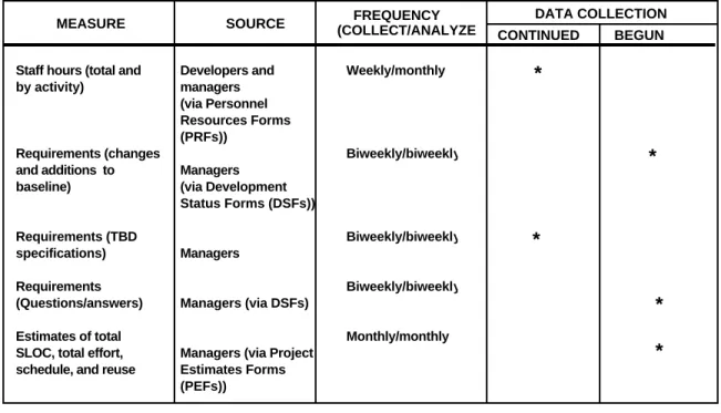
2-1 Measures Recommended by the SEL 1 8
3-1 Objective Measures Collected During the Requirements Definition Phase 3 1
4-1 Objective Measures Collected During the Requirements Analysis Phase 5 1
5-1 Objective Measures Collected During the Preliminary Design Phase 7 8
6-1 Objective Measures Collected During the Detailed Design Phase 9 7
7-1 Objective Measures Collected During the Implementation Phase 125
8-1 Objective Measures Collected During the System Testing Phase 151
FLIGHT DYNAMICS MISSION SUPPORT REQUIREMENTS PROVEN TECHNOLOGY FUTURE NEEDS • MISSION SUPPORT SOFTWARE • DEVELOPMENT AND MAINTENANCE OF OPERATIONAL SYSTEMS • MISSION ANALYSIS AND OPERATIONS • STABLE/UNCHANGING HARDWARE SYSTEMS DEVELOPMENT • ADVANCED SYSTEMS • RESEARCH AND DEVELOPMENT
• NEW TOOLS, METHODS, LANGUAGES • EXTENSIVE TOOLSETS FOR DEVELOPMENT • SEL DATABASE ADVANCED TECHNOLOGY FLIGHT DYNAMICS FACILITY SYSTEMS TECHNOLOGY LABORATORY
SECTION 1
INTRODUCTION
This document presents a set of guidelines that constitute a disciplined approach to software development. It is intended primarily for managers of software development efforts and for the technical personnel (software engineers, analysts, and programmers) who are responsible for implementing the recommended procedures. This document is neither a manual on applying the technologies described here nor a tutorial on monitoring a govern-ment contract. Instead, it describes the methodologies and tools that the Software Engineering Laboratory (SEL) recommends for use in each life cycle phase to produce manageable, reliable, cost-effective software.
THE FLIGHT DYNAMICS ENVIRONMENT
The guidelines included here are those that have proved effective in the experiences of the SEL (Reference 1). The SEL monitors and studies software developed in support of flight dynamics applications at the National Aeronautics and Space Administration/Goddard Space Flight Center (NASA/GSFC). Since its formation in 1976, the SEL has collected data from more than 100 software development projects. Typical projects range in size from approximately 35,000 to 300,000 delivered source lines of code (SLOC) and require from 3 to 60 staff-years to produce.
Flight dynamics software is developed in two distinct computing environments: the Flight Dynamics Facility (FDF) and the Systems Technology Laboratory (STL). (See Figure 1-1.) Mission support software is engineered and operated in the mainframe environment of the FDF. This software is used in orbit determination, orbit adjustment, attitude deter-mination, maneuver planning, and general mission analysis. Advanced concepts for flight dynamics are developed and studied in the STL. Software systems produced in this facility include simulators, systems requiring special architectures (e.g., embedded systems), flight
Section 1 - Introduction
dynamics utilities, and projects supporting advanced system studies. The STL also hosts the SEL database and the entire set of SEL research tools.
This revised edition of the Recommended Approach to Software
Development reflects the evolution in life cycle, development
methodology, and tools that has taken place in these environments in recent years. During this time, Ada and object-oriented design (OOD) methodologies have been introduced and used successfully. The potential for reuse of requirements, architectures, software, and documentation has been, and continues to be, studied and exploited. Ongoing studies also include experiments with the Cleanroom methodology (References 2 through 4), formal inspection, and computer-aided software engineering (CASE) tools.
Because the SEL's focus is process improvement, it is a catalyst for this evolution. The SEL continuously conducts experiments using the actual, production environment. The lessons learned from these experiments are routinely fed back into an evolving set of standards and practices that includes the Recommended Approach.
As these studies are confined to flight dynamics applications, readers of this document are cautioned that the guidance presented here may not always be appropriate for environments with significantly different characteristics.
DOCUMENT OVERVIEW
This document comprises 10 sections. Sections 3 through 9 parallel the phases of the software development life cycle through acceptance testing, and discuss the key activities, products, reviews, methodologies, tools, and metrics of each phase.
Section 1 presents the purpose, organization, and intended
Recent SEL papers on software maintenance include
"Measurement Based
Improvement of Maintenance i n the SEL," and "Towards Full Life Cycle Control, " both by Rombach, Ulery, and Valett. See References 5 and 6. REFERENCE
Section 4 discusses the key activities and products of the requirements analysis phase: requirements classifications,
walk-throughs, functional or object-oriented analysis, the requirements analysis report, and the software specifications review.
Section 5 presents the recommended approach to preliminary design. The activities, products, and methodologies covered
include structured and object-oriented design, reuse analysis, design walk-throughs, generation of prolog and program design language, the preliminary design report, and the preliminary design review.
Section 6 provides comparable material for the detailed design
phase. Additional topics include the build test plan, completion of prototyping activities, the critical design review, and the detailed design document.
Section 7 contains guidelines for i m pl e m e n t a t io n of the
designed software system. Coding, code reading, unit testing, and integration are among the activities discussed. The system test plan and user's guide are summarized.
Section 8 addresses system testing, including test plans, testing
methodologies, and regression testing. Also covered are preparation of the system description document and finalization of the acceptance test plan.
Section 9 discusses the products and activities of the acceptance testing phase: preparing tests, executing tests, evaluating results,
and resolving discrepancies.
Section 10 itemizes key DOs and DON'Ts for project success.
A list of a c r o n y m s , r e f e r e n c e s , a
bibliography of SEL literature, and an index conclude this document.
Although the m a i n t e n a n c e a n d
operation phase is beyond the scope of
the current document, efforts are now underway in the SEL to study this important part of the life cycle. The results of these studies will be incorporated into a future edition.
SECTION 2
THE SOFTWARE DEVELOPMENT LIFE CYCLE
The flight dynamics software development process is modeled as a series of eight sequential phases, collectively referred to as the software development
life cycle: 1. Requirements Definition 2. Requirements Analysis 3. Preliminary Design 4. Detailed Design 5. Implementation 6. System Testing 7. Acceptance Testing
8. Maintenance & Operation
Each phase of the software development life cycle is characterized by specific activities and the products produced by those activities.
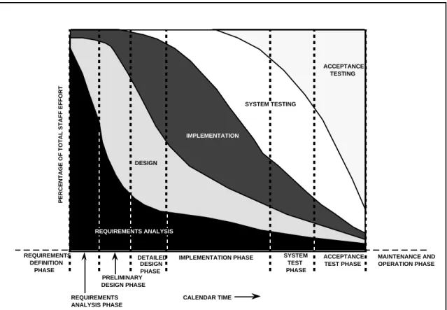
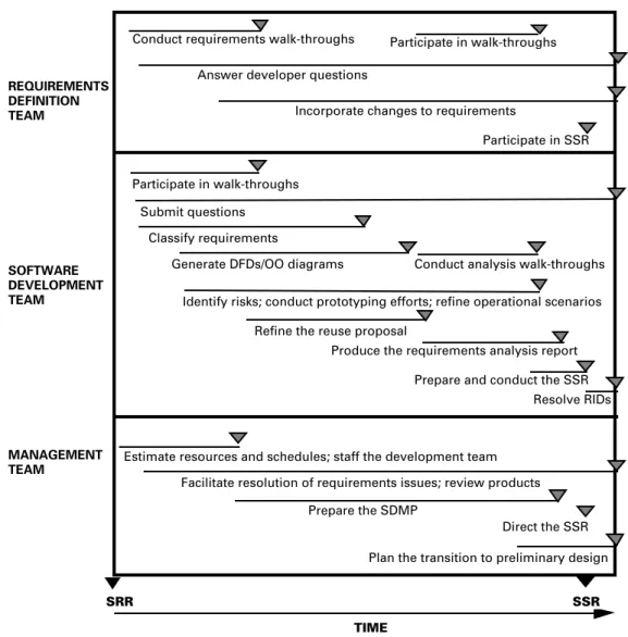
As shown in Figure 2-1, these eight phases divide the software life cycle into consecutive time periods that do not overlap. However, the activities characteristic of one phase may be performed in other phases. Figure 2-1 graphs the spread of activities throughout the development life cycle of typical flight dynamics systems. The figure shows, for example, that although most of the work in analyzing requirements occurs during the requirements analysis phase, some of that activity continues at lower levels in later phases as requirements evolve.
Section 2 - Life Cycle
PERCENTAGE OF TOTAL STAFF EFFORT
SYSTEM TEST PHASE IMPLEMENTATION PHASE REQUIREMENTS DEFINITION PHASE CALENDAR TIME DESIGN IMPLEMENTATION SYSTEM TESTING ACCEPTANCE TESTING PRELIMINARY DESIGN PHASE REQUIREMENTS ANALYSIS PHASE ACCEPTANCE TEST PHASE MAINTENANCE AND OPERATION PHASE DETAILED DESIGN PHASE REQUIREMENTS ANALYSIS
Example: At the end of the implementation phase (5th dashed line), approximately 46% of the staff are involved in system testing; approximately 15% are preparing for acceptance testing; approximately 7% are addressing requirements changes or problems; approximately 12% are designing modifications; and approximately 20% are coding, code reading, unit testing, and integrating changes. Data are shown only for the phases of the software life cycle for which the SEL has a representative sample.
Figure 2-1. Activities by Percentage of Total Development Staff Effort
PHASES OF THE LIFE CYCLE
The eight phases of the software development life cycle are defined in the following paragraphs.
NOTE
In this document, the term analyst refers to those specialists in flight dynamics (astronomers, mathematicians, physicists, and engineers) who determine the detailed requirements of the system and perform acceptance tests. For these activities, analysts work in teams (e.g., the
requirements definition team) and function as agents for the end users of the system.
NOTE
In each phase of the life cycle, certain milestones must be reached in order to declare the phase complete. Because the life cycle is
FINISH
sequential, these exit criteria are also the entry criteria for the following phase. In this document, entry and exit criteria are shown in the summary tables on the first page of Sections 3 through 9. A brief discussion of the phase's exit criteria is provided at the conclusion of each section.
Working with experienced developers, analysts identify any previously developed software that can be reused on the current project. The advantages and disadvantages of incorporating the existing components are weighed, and an overall architectural concept is negotiated. The results of these analyses are recorded in the system and
operations concept (SOC) document and assessed in
the system concept review (SCR).
Guided by the SOC, a requirements definition team derives a set of system-level requirements from documents provided by the mission project office. A draft version of the requirements is then recast in terms suitable for software design. These specifications define what data will flow into the system, what data will flow out, and what steps must be taken to transform input to output. Supporting mathematical information is included, and the completed requirements and specifications document is published. The conclusion of this phase is marked by the system requirements review
( S R R ) , during which the requirements and
specifications for the system are evaluated.
Requirements Analysis
The requirements analysis phase begins after the SRR. In this phase, the development team analyzes the requirements and specifications document for completeness and feasibility. The development team uses structured or object-oriented analysis and a requirements classification methodology to clarify and amplify the document. Developers work closely with the requirements definition team to resolve ambiguities, discrepancies, and to-be-determined (TBD) requirements or specifications.
The theme of reuse plays a prominent role throughout the requirements analysis and design phases. Special emphasis is placed on identifying potentially reusable architectures, designs, code, and approaches. (An overview of reuse in the life cycle is presented later in this section.)
When requirements analysis is complete, the development team prepares a summary requirements analysis report as a basis for
Section 2 - Life Cycle
requirements definition team then updates the requirements and specifications document to incorporate any necessary modifications.
Preliminary Design
The baselined requirements and specifications form a contract between the requirements definition team and the development team and are the starting point for preliminary design. During this phase, members of the development team define the software architecture that will meet the system specifications. They organize the requirements into major subsystems and select an optimum design from among possible alternatives. All internal and external interfaces are defined to the subsystem level, and the designs of high-level functions/objects are specified.
The development team documents the high-level design of the system in the preliminary design report. The preliminary design phase culminates in the preliminary design review (PDR), where the development team formally presents the design for evaluation.
Detailed Design
During the detailed design phase, the development team extends the software architecture defined in preliminary design down to the unit level. By successive refinement techniques, they elaborate the preliminary design to produce "code-to" specifications for the software. All formalisms for the design are produced, including the following:
• Functional or object-oriented design diagrams
• Descriptions of all user input, system output (for example, screen, printer, and plotter), and input/output files
• Operational procedures
• Functional and procedural descriptions of each unit • Descriptions of all internal interfaces
Implementation
In the implementation (code, unit testing, and integration) phase, the developers code new components from the design specifications and revise existing components to meet new requirements. They integrate each component into the growing system, and perform unit and integration testing to ensure that newly added capabilities function correctly.
In a typical project, developers build several subsystems simultaneously from individual components. The team repeatedly tests each subsystem as new components are coded and integrated into the evolving software. At intervals, they combine subsystem capabilities into a complete working system for testing end-to-end processing capabilities. The sequence in which components are coded and integrated into executable subsystems and the process of combining these subsystems into systems are defined in an implementation plan that is prepared by development managers during the detailed design phase.
The team also produces a system test plan and a draft of the user's
guide in preparation for the system testing phase that follows.
Implementation is considered complete when all code for the system has been subjected to peer review, tested, and integrated into the system.
System Testing
During the system testing phase, the development team validates the completely integrated system by testing end-to-end capabilities according to the system test plan. The system test plan is based on the requirements and specifications document. Successfully completing the tests specified in the test plan demonstrates that the system satisfies the requirements.
In this phase, the developers correct any errors uncovered by system tests. They also refine the draft user's guide and produce an initial
system description document. System testing is complete when all
tests specified in the system test plan have been run successfully.
Acceptance Testing
In the acceptance testing phase, the system is tested by an independent acceptance test team to ensure that the software meets
Section 2 - Life Cycle
NOTE
Recent SEL studies have shown that most of the effort in initial maintenance of flight dynamics systems is spent in enhancing
original requirements. The acceptance test team usually consists of analysts who will use the system and members of the requirements definition team.
The tests to be executed are specified in the acceptance test plan prepared by the acceptance test team before this phase. The plan is based on the contents of the requirements and specifications document and approved specification modifications.
During acceptance testing, the development team assists the test team and may execute acceptance tests under its direction. Any errors uncovered by the tests are corrected by the development team. Acceptance testing is considered complete when the tests specified in the acceptance test plan have been run successfully and the system has been formally accepted. The development team then delivers final versions of the software and the system documentation (user's guide and system description) to the customer.
Maintenance and Operation
At the end of acceptance testing, the system becomes the responsibility of a maintenance and operation group. The activities conducted during the maintenance and operation phase are highly dependent on the type of software involved. For most flight dynamics software, this phase typically lasts the lifetime of a spacecraft and involves relatively few changes to the software. For tools and general mission support software, however, this phase may be much longer and more active as the software is modified to respond to changes in the requirements and environment.
The maintenance and operation phase is not specifically addressed in this document. However, because enhancements and error corrections also proceed through a development life cycle, the recommended
RULE
The software development/ management plan (SDMP) must describe how the life cycle will be tailored for a specific project. See Section 4 for more details.
TAILORING THE LIFE CYCLE
One of the key characteristics that has shaped the SEL's recommended approach to software development is the homo-geneous nature of the problem domain in the flight dynamics environment. Most software is designed either for attitude determination and control for a specific mission, for mission-general orbit determination and tracking, or for mission planning. These projects progress through each life cycle phase sequentially, generating the standard documents and undergoing the normal set of reviews.
Certain projects, however, do not fit this mold. Within the STL, experiments are conducted to study and improve the development process. Advanced tools are developed. For these development efforts — prototypes, expert systems, database tools, Cleanroom experiments, etc. — the life cycle and the methodologies it incorporates often need adjustment. Tailoring allows variation in the level of detail and degree of formality of documentation and reviews, which may be modified, replaced, or combined in the tailoring process. Such tailoring provides a more exact match to unique project requirements and development products at a lower overall cost to the project without sacrificing quality.
The following paragraphs outline general guidelines for tailoring the life cycle for projects of varying size and type. Additional recommendations may be found throughout this document, accompanying discussions of specific products, reviews, methods, and tools.
Builds and Releases
The sizes of typical flight dynamics projects vary considerably. Simulators range from approximately 30 thousand source lines of code (KSLOC) to 160 KSLOC. Attitude ground support systems for specific missions vary between 130 KSLOC and 300 KSLOC, while large mission-general systems may exceed 1 million SLOC. The larger the project, the greater the risk of schedule slips, requirements changes, and acceptance problems. To reduce these
Section 2 - Life Cycle
NOTE
Reviews are recommended for each build. The suggested format and contents of build design reviews are provided in Section 7.
NOTE
Guidelines for tailoring the development approach (including reviews, documentation, and testing) for projects of differing scope and function are provided throughout this document. Look for the scissors symbol in the margin.
Flight dynamics projects with more than 10 KSLOC are implemented in builds. A build is a portion of a system that satisfies, in part or completely, an identifiable subset of the specifications. Specifications met in one build also are met in all successor builds. The last build, therefore, is the complete system.
A release is a build that is delivered for acceptance testing and subsequently released for operational use. Projects of fewer than 300 KSLOC are usually delivered in a single release, unless otherwise dictated by scheduling (e.g., launch) considerations or by TBD requirements. Large projects (more than 300 KSLOC) are generally delivered in multiple releases of 300 to 500 KSLOC each.
Builds within large projects may last up to 6 months. Builds within small projects may be only 2 to 3 months in duration.
Reviews
Reviews are conducted to ensure that analysts and developers understand and fulfill customer needs. Because reviews are designed to assist developers, not to burden them unnecessarily, the number of reviews held may vary from project to project. For tools development, the requirements, requirements analysis, and preliminary design might be reviewed together at PDR. For small projects spanning just several months, only two reviews may be applicable — the SRR and CDR. For very large projects, a CDR could (and should) be held for each major release and/or subsystem to cover all aspects of the system and to accommodate changing requirements.
The criteria used to determine whether one or more reviews can be combined depend on the development process and the life cycle
On small projects, technical reviews can be no more formal than a face-to-face meeting between the key personnel of the project and the customer technical representative. On typical flight dynamics projects, however, reviews are formalized and follow specific formats. Guidelines for these reviews are provided in Sections 3 through 9.
Documentation
On small projects, technical documentation is less formal than on medium or large projects, and fewer documents are published. Documents that would normally be produced separately on larger projects are combined. On a small research project, a single design document may replace the preliminary design report, detailed design document, and system description.
Testing and Verification
Independent testing is generally not performed on small-scale, tool-development efforts. Test plans for such projects can be informal. Although code reading is always performed on even the smallest project, units are often tested in logically related groups rather than individually, and inspections are usually conducted in informal, one-on-one sessions.
Configuration Management and Quality Assurance
Configuration management encompasses all of the activities
concerned with controlling the contents of a software system. These activities include monitoring the status of system components, preserving the integrity of released and developing versions of a system, and governing the effects of changes throughout the system. Quality assurance activities ensure that software development processes and products conform to established technical requirements and quality standards.
All software and documentation that are developed for delivery are generally subject to formal configuration management and quality assurance controls. Tools developed exclusively for internal use are exempt, unless the tool is required to generate, run, or test a deliverable system.
On medium and small projects, configuration control may be performed by a designated member of the development team — a
Section 2 - Life Cycle
RULE
All prototyping activities must be planned and controlled. The plan must define the purpose and scope of the prototyping effort, and must establish specific completion criteria. See Section 4 for more details.
WHEN TO PROTOTYPE
As a rule of thumb, use prototyping whenever
• the project involves new technology, e.g., new hardware, development
language, or system architecture • the requirements are not understood • there are major, unresolved issues
concerning performance, reliability, or feasibility
• the user interface is critical to system success or is not clearly understood
Prototyping
A prototype is an early experimental model of a system, system component, or system function that contains enough capabilities for it to be used to establish or refine requirements or to validate critical design concepts. In the flight dynamics environment, prototypes are used to (1) mitigate risks related to new technology (e.g., hardware, language, design concepts) or (2) resolve requirements issues. In the latter case, entire projects may be planned as prototyping efforts that are designed to establish the requirements for a later system. Unless the end product of the entire project is
a prototype, prototyping activities are usually completed during the requirements analysis and design phases. The prototyping activity has its own, usually informal, life cycle that is embedded within the early phases of the full system's life cycle. If any portion of the prototype is to become part of the final system, it must be validated through all the established checkpoints (design reviews, code reading, unit testing and certification, etc.). As a rule, such prototyping activities should require no more than 15 percent of the total development effort.
For projects in which the end product is a prototype, however, an iterative life cycle may be preferable. This is particularly true when a new user interface is a significant component of the system. An initial version of the prototype is designed, implemented, and demonstrated to the customer, who adds or revises requirements accordingly. The prototype is then expanded with additional builds, and the cycle continues until completion criteria are met.
KEY REUSE ELEMENTS Analyze these key elements of a project for possible reuse:
• requirements characteristics • software architecture
• software development process • design architecture or
concepts
• test plans and procedures • code
• user documentation • staff
REUSE THROUGHOUT THE LIFE CYCLE
From the beginning to the end of the life cycle, the approach to software development recommended by the SEL stresses the principle of reuse. Broadly speaking, the reuse of existing experience is a key ingredient to progress in any area. Without reuse, everything must be relearned and re-created. In software development, reuse eliminates having to "reinvent the wheel" in each phase of the life cycle, reducing costs and improving both reliability and productivity.
Planning for reuse maximizes these benefits by allowing the cost of the learning curve in building the initial system to be amortized over the span of follow-on projects. Planned reuse is a primary force behind such recent technologies as object-oriented design and Ada.
All experience and products of the software development life cycle — specifications, designs, documentation, test plans, as well as code — have potential for reuse. In the flight dynamics environment, particular benefits have been obtained by reusing requirements and specifi-cations (i.e., formats, key concepts, and high-level functionality) and by designing for reuse (see References 7 through 10).
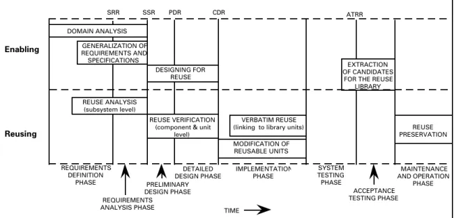
Figure 2-2 shows how reuse activities fit into the software development life cycle. The top half of the figure contains activities that are conducted to enable future reuse. The lower half shows activities in which existing software is used in the system under development. These activities are outlined in the following paragraphs.
Activities That Enable Future Reuse
Domain analysis is the examination of the application domain of the
development organization to identify common requirements and functions. It is usually performed during the requirements definition and analysis phases, but it may also be conducted as a separate activity unconnected to a particular development effort. Domain analysis produces a standard, general architecture or model that incorporates the common functions of a specific application area and can be tailored to accommodate differences between individual
domain analysis
Section 2 - Life Cycle MAINTENANCE AND OPERATION PHASE SSR SRR PDR CDR REUSE ANALYSIS (subsystem level) EXTRACTION OF CANDIDATES
FOR THE REUSE LIBRARY
REUSE VERIFICATION (component & unit
level) REQUIREMENTS DEFINITION PHASE REQUIREMENTS ANALYSIS PHASE PRELIMINARY DESIGN PHASE DETAILED DESIGN PHASE IMPLEMENTATION PHASE ACCEPTANCE TESTING PHASE SYSTEM TESTING PHASE TIME Enabling Reusing DOMAIN ANALYSIS GENERALIZATION OF REQUIREMENTS AND SPECIFICATIONS DESIGNING FOR REUSE MODIFICATION OF REUSABLE UNITS VERBATIM REUSE
(linking to library units) REUSE PRESERVATION ATRR
Figure 2-2. Reuse Activities Within the Life Cycle
Software not originally intended for reuse is more difficult to incorporate into a new system than software explicitly designed for reuse. Designing for reuse provides modularity, standard inter-faces, and parameterization. Design methods that promote reusability are described in References 9 and 11.
Reuse libraries hold reusable source code and associated
requirements, specifications, design documentation, and test data. In addition to storing the code and related products, the library contains a search facility that provides multiple ways of accessing the software (e.g., by keyword or name). On projects where reuse has been a design driver, extraction of candidate software for inclusion in the reuse library takes place after system testing is complete.
Reuse on Current Projects
designing for reuse
reuse libraries
reuse
preservation
NOTE
Sections 3 through 9 of this document provide detailed information about the objective measures used in each phase. Look for the MEASURES heading and symbol.
Software may be reused verbatim or may be modified to fit the needs of the current project. During the implementation phase, developers integrate existing, unchanged units into the developing system by linking directly to the reuse library. Modified software, on the other hand, must be subjected to peer review and unit testing before being integrated.
A final reuse activity takes place during the maintenance and operation phase of the life cycle. Through the changes that it implements, the maintenance team can positively or negatively affect the reusability of the system; "quick fixes", for example, may complicate future reuse. Reuse preservation techniques for maintenance use many of the same practices that promote reuse during the analysis, design, and implementation phases.
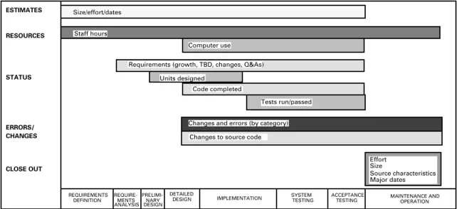
MEASURES
Measures of project progress and viability are key to the effective management of any software development effort. In each phase of the life cycle, there are certain critical metrics that a manager must examine to evaluate the progress, stability, and quality of the development project.
Both o b j e c t i v e and s u b j e c t i v e data are measured. Objective data are actual counts of items (e.g., staff hours, SLOC, errors) that can be independently verified. Subjective data are dependent on an individual's or group's assessment of a condition (e.g., the level of difficulty of a problem or the clarity of requirements). Together, these data serve as a system of checks and balances. Subjective data provide critical information for interpreting or validating objective data, while objective data provide definitive counts that may cause the manager to question his or her subjective understanding and to investigate further.
Objective measures can be further classified into two groups: those that measure progress or status and those that measure project quality (e.g., stability, completeness, or reliability). Progress measures, such as the number of units coded or the number of tests passed, are evaluated against calculations of the total number of
Section 2 - Life Cycle
Table 2-1. Measures Recommended by the SEL
Estimates of: •Total SLOC (new, modified, reused) • Total units • Total effort • Major dates • Staff hours
(total & by activity) • Computer use • Requirements (growth, TBDs, changes, Q&As) • Units designed, coded, tested • SLOC (cumulative) • Tests (complete, passed) • Errors (by category) • Changes (by category)
• Changes (to source) Actuals at completion: • Effort • Size (SLOC, units) • Source characteristics • Major dates
MEASURE SOURCE FREQUENCY MAJOR APPLICATION
Managers Developers Automated tool Managers Developers Automated Developers Developers Developers Automated Managers Monthly Weekly Weekly Biweekly Biweekly Weekly Biweekly By event By event Weekly 1 time, at completion • Project stability • Planning aid • Project stability • Replanning indicator • Effectiveness/impact of the development process being applied • Project progress • Adherence to defined process
• Stability and quality of requirements
• Effectiveness/impact of the development process • Adherence to defined
process
• Build predictive models • Plan/manage new projects
MEASURES CLASS ESTIMATES RESOURCES STATUS ERRORS/ CHANGES FINAL CLOSE-OUT
only useful if the manager has access to models or metrics that represent what should be expected.
In the SEL, measurement data from current and past projects are stored in a project
ESTIMATES RESOURCES STATUS ERRORS/ CHANGES CLOSE OUT REQUIRE-MENTS ANALYSIS DETAILED
DESIGN IMPLEMENTATION SYSTEM TESTING ACCEPTANCETESTING
PRELIMI-NARY DESIGN REQUIREMENTS
DEFINITION MAINTENANCE AND OPERATION
Size/effort/dates
Staff hours
Computer use
Changes and errors (by category) Changes to source code Units designed
Code completed
Tests run/passed Requirements (growth, TBD, changes, Q&As)
Effort Size
Source characteristics Major dates
Figure 2-3. Graph Showing in Which Life-Cycle Phases Each Measure Is Collected
EXPERIMENTATION
Measurement is not only essential to the management of a software development effort; it is also critical to software process improvement. In the SEL, process improvement is a way of life. Experiments are continually being conducted to investigate new software engineering technologies, practices, and tools in an effort to build higher-quality systems and improve the local production process. The SEL's ongoing measurement program provides the baseline data and models of the existing development environment against which data from experimental projects are compared.
For several years, the SEL has been conducting experiments and measuring the impact of the application of the Cleanroom methodology (References 2, 3, and 4), which was developed in the early 1980s by Harlan Mills. The goal of the Cleanroom methodology is to build a software product correctly the first time. Cleanroom stresses disciplined "reading" techniques that use the human intellect to verify software products; testing is conducted for the purpose of quality assessment rather than as a method for detecting and repairing errors.
Section 2 - Life Cycle
DEFINITION
The term Cleanroom was borrowed from integrated circuit production. It refers to the dust-free environments in which the circuits are assembled.
Consequently, the Cleanroom methodology is used throughout this document as an example of the integral aspect of experimentation and process improvement to the SEL's recommended approach. Variations in life cycle processes, methods, and tools resulting from the application of Cleanroom will be highlighted. Look for the experimentation symbol.
LIFE CYCLE PHASES REQUIRE-MENTS ANALYSIS DETAILED
DESIGN IMPLEMENTATION TESTINGSYSTEM
ACCEPTANCE TESTING PRELIMI-NARY DESIGN REQUIREMENTS DEFINITION
SECTION 3
THE REQUIREMENTS DEFINITION PHASE
Requirements Definition Team
ENTRY CRITERIA
• System and operations concept completed • SRR completed
• Requirements and specifications baselined
EXIT CRITERIA
MEASURES
PRODUCTS KEY ACTIVITIES
PHASE HIGHLIGHTS
• System and operations concept document • Requirements and specifications
document
• Staff hours
• Number of requirements defined vs. estimated total requirements • Percentage of requirements with
completed specifications
Requirements Definition Team • Develop a system concept • Prepare the reuse proposal • Develop an operations concept • Define the detailed requirements • Derive the specifications
• Conduct the SCR and SRR Management Team
• Develop a plan for the phase • Staff and train the requirements
definition team
• Interact with the customer • Evaluate progress and products • Control major reviews
• Problem/project description completed • Project approved
METHODS AND TOOLS
• Structured or object-oriented analysis • Walk-throughs
Section 3 - Requirements Definition
NOTE
In the flight dynamics
NOTE (cont.)
analysts from the requirements OVERVIEW
The purpose of the requirements definition phase is to produce a clear, complete, consistent, and testable specification of the technical requirements for the software product.
Requirements definition initiates the software development life cycle. During this phase, the requirements definition team uses an iterative process to expand a broad statement of the system requirements into a complete and detailed specification of each function that the software must perform and each criterion that it must meet. The finished requirements and specifications, combined with the system and operations concept, describe the software product in sufficient detail so that independent software developers can build the required system correctly.
The starting point is usually a set of high-level requirements from the customer that describe the project or problem. For mission support systems, these requirements are extracted from project documentation such as the system instrumentation requirements document (SIRD) and the system operations requirements document (SORD). For internal tools, high-level requirements are often simply a list of the capabilities that the tool is to provide.
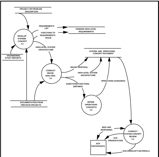
In either case, the requirements definition team formulates an overall concept for the system by examining the high-level requirements for similarities to previous missions or systems, identifying existing software that can be reused, and developing a preliminary system architecture. The team then defines scenarios showing how the system will be operated, publishes the system and operations concept document, and conducts a system concept review (SCR). (See Figure 3-1.)
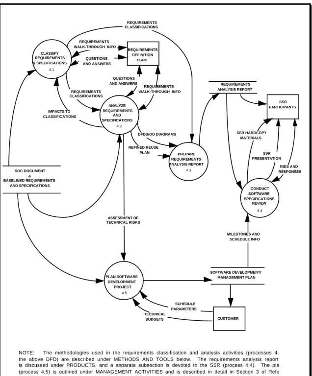
Following the SCR, the team derives detailed requirements for the system from the high-level requirements and the
SCR PRESENTATION DEVELOP SYSTEMS CONCEPT 3.1 SCR-HARDCOPY-MATERIALS CONDUCT REUSE ANALYSES 3.2 DEFINE OPERATIONS CONCEPTS 3.3 CONDUCT SYSTEM CONCEPT REVIEW 3.4 RIDS AND RESPONSES SYSTEM AND OPERATIONS
CONCEPT DOCUMENT OPERATIONS SCENARIOS REUSE PROPOSAL HIGH-LEVEL SYSTEM ARCHITECTURE ITEMIZED HIGH-LEVEL REQUIREMENTS PROJECT OR PROBLEM DESCRIPTION ENGINEERING STUDY REPORTS FUNCTIONS TO REQUIREMENTS TRACE DOCUMENTATION FROM PREVIOUS PROJECTS SUBSYSTEM FUNCTIONS (REFINED) REQUIREMENTS LIST SCR PARTICIPANTS HIGH-LEVEL SYSTEM ARCHITECTURE
NOTE: In this figure, as in all data flow diagrams (DFDs) in this document, rectangles denote external entities, circles represent processes, and parallel lines are used for data stores (in this case, documents). The processes labelled 3.1, 3.2, and 3.3 are described in the KEY ACTIVITIES subsection below. The SCR is described under REVIEWS and the system and operations concept document is covered in PRODUCTS.
Figure 3-1. Generating the System and Operations Concept
When the specifications are complete, the requirements definition team publishes the requirements and specifications document in three parts: (1) the detailed requirements, (2) the functional or object-oriented specifications, and (3) any necessary mathematical
Section 3 - Requirements Definition ANALYZE HIGH-LEVEL REQUIREMENTS 3.5 SRR HARDCOPY MATERIALS DEFINE DETAILED REQUIREMENTS 3.6 DEVELOP SPECIFICATIONS 3.7 CONDUCT SYSTEM REQUIREMENTS REVIEW 3.8 SYSTEM AND OPERATIONS
CONCEPT DOCUMENT
INTERFACE CONTROL DOCUMENTS PROJECT OR PROBLEM DESCRIPTION INFORMATION FROM PREVIOUS PROJECTS REQUIREMENTS AND SPECIFICATIONS DOCUMENT PERFORMANCE ANALYSES DETAILED REQUIREMENTS DETAILED REQUIREMENTS SPECIFICATIONS TRACEABILITY MATRIX SPECIFICATIONS MATH BACKGROUND ITEMIZED HIGH-LEVEL REQUIREMENTS
SRR PRESENTATION RIDS AND RESPONSES SRR PARTICIPANTS
NOTE: The processes labelled 3.5, 3.6, and 3.7 are discussed in the KEY ACTIVITIES subsection. The requirements and specifications document is described under the heading PRODUCTS. The REVIEWS subsection covers the SRR.
TAILORING NOTE
On small projects that are developing tools or prototypes, requirements definition and analysis are often combined into a single phase. On such projects, developers generally perform all requirements definition activities.
Although use of existing software can reduce effort significantly, some compromises may be necessary. Ensure that all tradeoffs are well understood. Avoid these two pitfalls:
• Failing to make reasonable compromises, thus wasting effort for marginal
improvement in quality or functionality • Making ill-advised compromises that save development effort at the cost of
REUSE NOTE
KEY ACTIVITIES
The key technical and managerial activities of the requirements definition phase are itemized below.
Activities of the Requirements Definition Team
• Develop a system concept. Collect and itemize all high-level requirements for the system. Describe the basic functions that the system must perform to satisfy these high-level requirements. Address issues such as system lifetime (usage timelines), performance, security, reliability, safety, and data volume.
From this functional description, generate an ideal, high-level system architecture identifying software programs and all major interfaces. Allocate each high-level requirement to software, hardware, or a person. Specify the form (file, display, printout) of all major data interfaces.
• Prepare the reuse proposal. Review the requirements and specifications, system descriptions, user's guides, and source code of related, existing systems to identify candidates for reuse. For flight dynamics mission support systems, this involves reviewing support systems for similar spacecraft. Select strong candidates and estimate the corresponding cost and reliability benefits. Determine what compromises are necessary to reuse software and analyze the tradeoffs.
Adjust the high-level architecture to account for reuseable software. Record the results of all reuse analysis in a reuse proposal that will be included in the system and operations concept document. • Develop an operations concept. This clearly
defines how the system must operate within its environment. Include operational scenarios for all major modes of operation (e.g., emergency versus normal). Be sure to include the end-user in this process. Conduct an SCR.
Section 3 - Requirements Definition
NOTE
See the PRODUCTS subsection below for detailed contents of the system and operations concept as well as the requirements and functional specifications documents. NOTE The SCR and SRR are covered in detail in the REVIEWS subsection. TAILORING NOTE
On very large or complex projects,
• D e f i n e t h e d e t a i l e d requirements. Based on the high-level requirements and the system concept and architecture, define all software requirements down to the subsystem level. If the system is large (with many subsystems) or if it will interface with other systems, explicitly define all external interfaces.
Determine system performance and reliability requirements. If certain acceptance criteria apply to a requirement (e.g., meeting a particular response time), specify the test criteria with the requirement. Identify all intermediate products needed to acceptance test the system.
• Derive the functional specifications for the system from the requirements. Identify the primary input and output data needed to satisfy the requirements. Use structured or object-oriented analysis to derive the low-level functions and algorithms the software must perform. Define all reports and displays and indicate which data the user must be able to modify.
Keep the specifications design-neutral and language-neutral; i.e., concentrate on what the software needs to do, rather than how it will do it. Create a traceability matrix to map each low-level function or data specification to the requirements it fulfills. Ensure that all requirements and
specifications are given a thorough peer review. Watch for interface problems among major functions and for specifications that are duplicated in
DEFINITION
The key developers who participate in reuse analysis and other requirements definition activities have special technical roles throughout the life cycle. The value of these application specialists lies in their specific knowledge and experience. On mission support projects, for example, the application specialist will not only have developed such software previously, but also will understand the complex mathe-matics and physics of flight dynamics. The application specialist often acts as a "translator," facilitating communications
• Conduct the SRR and incorporate approved changes into the requirements and specifications. Place the document under configuration management as the system baseline.
Activities of the Management Team
The management activities performed during this phase pave the way for all future phases of the project's life cycle. Specifically, managers must accomplish the following:
• Develop a plan for the phase. (Detailed planning of the entire development effort is deferred to the requirements analysis phase, after system specifications have been defined.) Address the staffing of the teams that will perform the technical work, the groups and individuals that will interface with the teams, the technical approach, milestones and schedules, risk management, and quality assurance. List the reviews to be conducted and their level of formality.
• Staff and train the requirements definition team. Ensure that the team contains the necessary mix of skills and experience for the task. For mission support systems, the team should include analysts with strong backgrounds in mission analysis, attitude and orbit determination, and operations. The reuse working group must include key software developers as well as experienced analysts. Ensure that staff members have the necessary training in the procedures, methods, and tools needed to accomplish their goals.
• Interact with the customer to assure visibility and resolution of all issues. Conduct regular status meetings and ensure communications among team members, managers, customers, and other groups working on aspects of the project.
• Evaluate progress and products. Review the system and operations concept and the requirements and specifications. Collect progress measures and monitor adherence to schedules and cost.
Section 3 - Requirements Definition
METHODS AND TOOLS
The methods and tools used during the requirements definition phase are
• Structured or object-oriented analysis • Walk-throughs
• Prototyping
Each is discussed below.
Analysis Methodologies
Structured analysis and object-oriented analysis are techniques used
to understand and articulate the implications of the textual statements found in the requirements definition. The requirements definition team uses analysis techniques to derive the detailed specifications for the system from the higher-level requirements. The analysis methodology selected for the project should be appropriate to the type of problem the system addresses.
Functional decomposition is currently the most commonly used method of structured analysis. Functional decomposition focuses on processes, each of which represents a set of transformations of input to output. Using this method, the analyst separates the primary system function into successively more detailed levels of processes and defines the data flows between these processes. Authors associated with structured analysis include E. Yourdon, L.Constantine, and T. DeMarco (References 13 and 14). S. Mellor and P. Ward have published a set of real-time extensions to this method for event-response analysis (Reference 15).
Object-oriented analysis combines techniques from the realm of data engineering with a process orientation. This method defines the objects (or entities) and attributes of the real-world problem domain and their interrelationships. The concept of an object provides a means of focusing on the persistent aspect of entities — an emphasis different from that of structured analysis. An object-oriented
structured analysis
object-oriented analysis
NOTE
CASE tools can greatly increase productivity, but they can only aid or improve those activities that the team or individual knows how to perform manually. CASE tools cannot improve analysis, qualify designs or code, etc., if the user does not have have a clear definition of the manual process involved.
recasting the data flow diagrams. This is a significant amount of effort that can be avoided by assuming an object-oriented viewpoint during the requirements definition phase. The diagramming capabilities of CASE tools facilitate application of the chosen analysis methodology. The tools provide a means of producing and maintaining the necessary data flow and object-diagrams online. They usually include a centralized repository for storing and retrieving definitions of data, processes, and entities. Advanced tools may allow the specifications themselves to be maintained in the repository, making it easier to trace the requirements to design elements.
Selected tools should be capable of printing the diagrams in a form that can be directly integrated into specifications and other documents. Examples of CASE tools currently used in the flight dynamics environment include System Architect and Software Through Pictures.
Walk-throughs
In all phases of the life cycle, peer review ensures the quality and consistency of the products being generated. The SEL recommends two types of peer review — walk-throughs and inspections — in addition to formal reviews such as the SRR and CDR.
Walk-throughs are primarily conducted as an aid to understanding, so participants are encouraged to analyze and question the material under discussion. Review materials are distributed to participants prior to the meeting. During the meeting, the walk-through leader gives a brief, tutorial overview of the product, then walks the reviewers through the materials step-by-step. An informal atmosphere and a free interchange of questions and answers among participants fosters the learning process.
Inspections, on the other hand, are designed to uncover errors as early as possible and to ensure a high-quality product. The inspection team is a small group of peers who are technically competent and familiar with the application, language, and standards used on the project. The products to be reviewed (e.g.,
walk-throughs
Section 3 - Requirements Definition
standards, and they come to the review meeting prepared to itemize and discuss any problems.
In both walk-throughs and inspections, a designated team member records the minutes of the review session, including issues raised, action items assigned, and completion schedules. Closure of these items is addressed in subsequent meetings.
In the requirements definition phase, walk-throughs of the requirements and specifications are conducted to ensure that key interested parties provide input while requirements are in a formative stage. Participants include the members of the requirements definition team, representatives of systems that will interface with the software to be developed, and application specialists from the development team.
Prototyping
During the requirements definition phase, prototyping may be needed to help resolve requirements issues. For mission support systems, analysts use prototyping tools such as MathCAD to test the mathematical algorithms that will be included in the specifications. For performance requirements, platform-specific performance models or measurement/monitoring tools may be used.
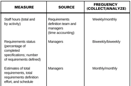
MEASURES
Objective Measures
Three progress measures are tracked during the requirements definition phase:
• Staff hours — i.e., the cumulative effort hours of the project staff
• Number of requirements with completed specifications versus the total number of requirements
staff hours
MEASURE SOURCE (COLLECT/ANALYZE)FREQUENCY
Staff hours (total and by activity) Requirements status (percentage of completed specifications; number of requirements defined) Estimates of total requirements, total requirements definition effort, and schedule
Requirements definition team and managers (time accounting) Managers Managers Weekly/monthly Biweekly/biweekly Monthly/monthly
Table 3-1. Objective Measures Collected During the Requirements Definition Phase
Evaluation Criteria
Effort should be gauged against estimates based on historical data from past projects of a similar nature. Monitor staff hours separately for each major activity. If schedules are being met but hours are lower than expected, the team may not be working at the level of detail necessary to raise problems and issues.
To judge progress following the SCR, track the number of requirements for which specifications have been written as a percentage of the total number of requirements. ("Total require-ments" includes those for which a need has been identified, but for which details are still TBD.)
Monitor requirements growth by tracking the number of requirements that have been defined against an estimated total for the project. If requirements stability is an issue, consider tracking the number of changes made to requirements as well. Excessive growth or change to specifications point to a need for greater management control or to the lack of a detailed system operations concept.
completed specifications
defined requirements
Section 3 - Requirements Definition
PRODUCTS
The key products of the requirements definition phase are the system and operations concept (SOC) document and the requirements and specifications document. The content and form of these products are addressed in the following paragraphs.
System and Operations Concept Document
The SOC document lists the high-level requirements, defines the overall system architecture and its operational environment, and describes how the system will operate within this environment. The document provides a base from which developers can create the software structure and user interface. The format recommended for the document is shown in Figure 3-3.
The SOC is not usually updated after publication. During the requirements analysis phase, developers refine the reuse proposal contained in the document and publish the resulting reuse plan in the requirements analysis report. Similarly, developers refine the operational scenarios and include them in the requirements analysis, preliminary design, and detailed design reports. Because these and other pieces of the SOC are reworked and included in subsequent development products, it may not be necessary to baseline or maintain the SOC itself.
Requirements and Specifications Document
This document is produced by the requirements definition team as the key product of the requirements definition phase. It is often published in multiple volumes: volume 1 defines the requirements, volume 2 contains the functional specifications, and volume 3 provides mathematical specifications. The document is distributed prior to the SRR, updated following the review to incorporate approved review items, and then baselined.
SYSTEM AND OPERATIONS CONCEPT DOCUMENT
This document provides a top-down view of the system from the user’s perspective by describing the behavior of the system in terms of operational methods and scenarios. Analysts should provide the document to the development team by the end of the requirements definition phase. The suggested contents are as follows:
1. Introduction
a. Purpose and background of the system b. Document organization
2. System overview a. Overall system concept
b. System overview with high-level diagrams showing external interfaces and data flow c. Discussion and diagrams showing an ideal, high-level architecture for the system 3. Reuse proposal
a. Summary of domain and reuse analysis performed
b. Description of potential candidates for reuse — architectural components, designs, operational processes, and test approaches — and associated trade-offs c. Discussion and diagrams of the proposed high-level architecture, as adjusted to
incorporate reusable elements
4. Operational environment — description and high-level diagrams of the environment in which the system will be operated
a. Overview of operating scenarios
b. Description and high-level diagrams of the system configuration (hardware and software) c. Description of the responsibilities of the operations personnel
5. Operational modes
a. Discussion of the system's modes of operation (e.g., critical versus normal and launch/early mission versus on-orbit operations)
b. Volume and frequency of data to be processed in each mode
c. Order, frequency, and type (e.g., batch or interactive) of operations in each mode 6. Operational description of each major function or object in the system
a. Description and high-level diagrams of each major operational scenario showing all input, output, and critical control sequences
b. Description of the input data, including the format and limitations of the input. Sample screens (i.e., displays, menus, popup windows) depicting the state of the function before receiving the input data should also be included.
c. Process — high-level description of how this function will work
d. Description of the output data, including the format and limitations of the output. Samples (i.e., displays, reports, screens, plots) showing the results after processing the input should also be included.
e. Description of status and prompt messages needed during processing, including guidelines for user responses to any critical messages
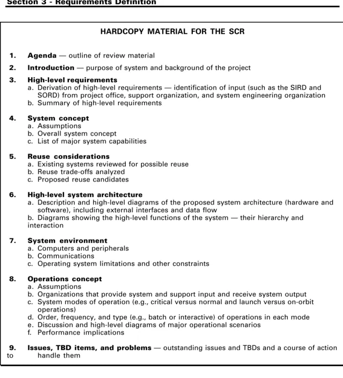
The recommended outline for the requirements and specifications document is presented in Figure 3-4.
Section 3 - Requirements Definition
REQUIREMENTS AND SPECIFICATIONS DOCUMENT
This document, which contains a complete description of the requirements for the software system, is the primary product of the requirements definition phase. In the flight dynamics environment, it is usually published in three volumes: volume 1 lists the requirements, volume 2 contains the functional specifications, and volume 3 provides the mathematical specifications.
1. Introduction
a. Purpose and background of the project b. Document organization
2. System overview a. Overall system concept
b. Expected operational environment (hardware, peripherals, etc.)
c. High-level diagrams of the system showing the external interfaces and data flows d. Overview of high-level requirements
3. Requirements — functional, operational (interface, resource, performance, reliability, safety, security), and data requirements
a. Numbered list of high-level requirements with their respective derived requirements (derived requirements are not explicitly called out in source documents such as the SIRD or SORD, but represent constraints, Iimitations, or implications that must be satisfied to achieve the explicitly stated requirements)
b. For each requirement:
(1) Requirement number and name (2) Description of the requirement
(3) Reference source for the requirement, distinguishing derived from explicit requirements
(4) Interfaces to other major functions or external entities
(5) Performance specifications — frequency, response time, accuracy, etc. 4. Specifications
a. Discussion and diagrams showing the functional or object hierarchy of the system b. Description and data flow/object diagrams of the basic processes in each major subsystem
c. Description of general conventions used (mathematical symbols, units of measure, etc.) d. Description of each basic function/object, e.g.:
(1) Function number and name (2) Input
(3) Process — detailed description of what the function should do (4) Output
(5) Identification of candidate reusable software
(6) Acceptance criteria for verifying satisfaction of related requirements
(7) Data dictionary — indicating name of item, definition, structural composition of the item, item range, item type