© Global Society of Scientific Research and Researchers http://asrjetsjournal.org/
Enhancement of Cluster-based Routing Protocol with
Parameters Consideration in Wireless Sensor Network
Ei Ei Mon
a*, Myo Myint Maw
b, May Zin Oo
ca,b,cDepartment of Computer Engineering and Information Technology, Mandalay Technological University,
Mandalay, The Republic of Union of Myanmar
a Email: [email protected] b Email: [email protected] cEmail: [email protected] Abstract
A wireless sensor network (WSN) consists of large number of battery operated sensor nodes which are generally deployed in different environments. These sensor nodes have limited energy to sense, process and transmit information. Therefore, there is a need to design an energy efficient routing protocol to extend the lifetime of a WSN. Low Energy Adaptive Clustering Hierarchy (LEACH) protocols are considered to optimize the energy consumption. In this paper, a cluster based routing protocol called Enhancement of Cluster-based Routing Protocol with Parameter Consideration (ECRP-PC) is proposed, in which an assistant Cluster Head called Vice Cluster Head (VCH) is introduced in addition to Cluster Head (CH). In a cluster, the node with the highest residual energy among all nodes is selected as the CH, and the node with second highest residual energy is selected by the CH as the VCH when the cluster head distance is longer than the specified distance. VCH will serve as a backup node of the CH. The selected VCH will be in a sleep mode as long as the energy of CH is above a threshold, and it will become active when the energy of CH is below a threshold. According to the results, the proposed ECRP-PC protocol is able to increase the average lifetime of nodes up to 56% compared to the original LEACH.
Keywords: Wireless Sensor Network; Cluster Head; LEACH; ECRP-PC; Vice Cluster Head; Specified Distance; Lifetime.
--- * Corresponding author.
1. Introduction
Advances in wireless communication technology are enabling the deployment of networks composed of small sensor nodes. They can communicate with one another without any required infrastructure or central management. These nodes in WSN in numerous limited resources is intended to design routing protocols with the aim of reducing energy dissipated and maximizing the lifetime of the network. To control the network, the complete network is divided into sub networks called clusters and each cluster is controlled by centralized cluster head. Wireless sensor network is used for home automation, environmental monitoring, flood detection, forest and fire detection, etc. Sensor nodes collect all data and send them to the sink node which is known as base station (BS). The BS sends data to the end users for further processing through internet facility. Increasing lifetime is very important for various data aggregation techniques which are based on the routing and clustering. The hierarchical routing protocol is more energy efficient than other routing protocols. In each cluster, single node is considered as cluster head and non-cluster head nodes, which are treated as cluster members. Every cluster head gathers data from cluster member and aggregates these data and broadcasts them to the base station through single hop or multi hop. Cluster head needs more energy than a cluster member. A hierarchical routing protocol is designed to reduce energy consumption and aggregate data to quickly transmit to the base station. There are two types of well-known hierarchical routing protocols, which are Low Energy Adaptive Clustering Hierarchy (LEACH) and Power-efficient Gathering in Sensor Information System (PEGASIS) [3]. LEACH is the first hierarchical cluster based routing protocol. Cluster head in LEACH is responsible for creating and manipulating a time division multiple accesses. LEACH protocol provides a significant reduction of overall energy other than non-clustering protocols. Benefits of clustering architecture are the low power consumption, improved fault tolerance, reduction of congestion. LEACH protocol uses random cluster head selection and does not cover the wide range of area. Therefore, LEACH protocol is chosen to be enhanced in order to get more energy efficient clustering protocol in WSNs.
2. Hierarchical Clustering in Wireless Sensor Network
Hierarchical clustering [7, 8] is an efficient way to utilize the energy in grouping sensor nodes into clusters. In hierarchical cluster, there may be many cluster heads, member nodes and one base station. After clustering, the cluster heads are chosen to collect the data from all member nodes. Using CHs increases the network lifetime because all nodes need not involve in a direct transmission to the BS. However, the CHs utilize more energy for temporarily caching the data and relying to the BS. Thus, cluster formation and CH selection are very important to reduce the energy consumption. While designing the clusters in WSN, there are several key attributes [9] which must be carefully considered.
2.1.Clustering Parameters
• Number of Clusters - It may be varied according to the CH selection algorithms. In some cases it could be a predefined value.
• Nodes and CH Mobility - Cluster formation is dynamically changed when the sensor nodes are in mobility.
• Node Type and Roles - Nodes may be in homogeneous or heterogeneous nature. In homogeneous nature, all sensor nodes have same capabilities such as same energy level. In heterogeneous system, nodes are varied in configurations.
• Cluster Head Selection - CHs are selected from the deployed nodes based on the criteria such as residual energy, connectivity, communication cost and mobility.
2.2. Issues to Be Considered in Clustering
Several key attributes need to be considered in clustering the sensor nodes.
• Limited Energy - Unlike energetic designs, wireless sensor nodes are off-grid, meaning that these nodes have limited energy storage and the efficient use of energy will be vital in determining the range of suitable applications for these networks. The limited energy in sensor nodes must be considered because proper clustering can reduce the overall energy usage in a network.
• Network Lifetime - The limited energy of nodes results in a limited network lifetime. Proper clustering should attempt to reduce the energy usage, and hereby increase network lifetime.
• Limited Abilities - The small physical size and small amount of stored energy in a sensor node limit the processing and communication abilities.
• Application Dependency - Often a given application will heavily rely on cluster organization. When designing a clustering algorithm, application robustness must be considered because a good clustering algorithm should be able to adapt to a variety of application requirements.
3. Radio Energy Dissipation Model
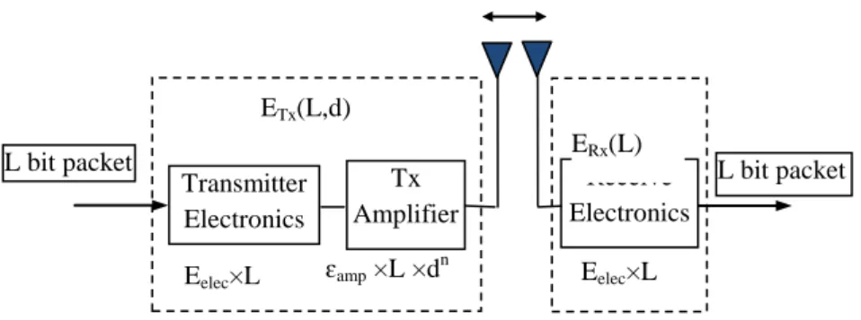
First order radio communication model introduced in [2] is considered as the radio energy module to access the energy dissipation. This radio model has three modules: the transmitter, the power amplifier, and the receiver as shown in figure 1. The distance between the transmitter and receiver is defined by d. The power amplifier consumes energy for transmitting data [2].
Figure 1: Radio Energy Dissipation Model
There are basically two propagation models: ETx(L,d) Eelec×L L bit packet Tx Amplifier Transmitter Electronics Receive Electronics ɛamp ×L ×dn Eelec×L d L bit packet ERx(L)
1. Free space propagation model and
2. Two-ray ground propagation model [2].
The free space propagation model is the model where there is direct line of sight path between the transmitter and the receiver. The two-ray ground propagation model is the model where the propagation between the transmitter and the receiver is not direct and the electromagnetic waves will bounce off the ground and arrive at the receiver from different paths at different instant of time.
The power amplifier can be used to amplify the transmitting power to compensate propagation loss during the transmission. Thus, the energy dissipation for transmitting 𝐿𝐿 bit message from the transmitter to the receiver at the distance 𝑑𝑑 is defined as:
𝐸𝐸𝑇𝑇𝑇𝑇(𝐿𝐿,𝑑𝑑) = �𝐿𝐿×�𝐸𝐸𝑒𝑒𝑒𝑒𝑒𝑒𝑒𝑒+ 𝐿𝐿𝐿𝐿𝑓𝑓𝑓𝑓×𝑑𝑑
2�,𝑖𝑖𝑖𝑖𝑑𝑑 ≤ 𝑑𝑑 0
𝐿𝐿×�𝐸𝐸𝑒𝑒𝑒𝑒𝑒𝑒𝑒𝑒+ 𝐿𝐿𝐿𝐿𝑚𝑚𝑚𝑚×𝑑𝑑4�,𝑖𝑖𝑖𝑖𝑑𝑑>𝑑𝑑0 (1)
If the distance between the transmitter and the receiver is larger than the cross-over distance, the two ray ground model is used. Otherwise, the free space model is considered to measure the energy dissipation. Energy required for receiving 𝐿𝐿 bits message [4] is
𝐸𝐸𝑅𝑅𝑇𝑇(𝐿𝐿) = 𝐿𝐿𝐸𝐸𝑒𝑒𝑒𝑒𝑒𝑒𝑒𝑒 (2)
where𝐸𝐸𝑇𝑇𝑇𝑇and𝐸𝐸𝑅𝑅𝑇𝑇is the energy dissipated by the transmitter and receiver, respectively. d 𝐸𝐸𝑒𝑒𝑒𝑒𝑒𝑒𝑒𝑒 is the energy dissipated per bit to run the transceiver circuit. The parameters 𝐿𝐿𝑓𝑓𝑓𝑓 and 𝐿𝐿𝑚𝑚𝑚𝑚are the amplifier parameters for the free space propagation model and the two-ray ground propagation model respectively. The crossover distance 𝑑𝑑0 can be obtained from
𝑑𝑑0=�ɛɛfs
𝑚𝑚𝑚𝑚 (3)
4. Low Energy Adaptive Clustering Hierarchy
Low-Energy Adaptive Clustering Hierarchy (LEACH) is a cluster-based energy efficient routing protocol for sensor networks proposed by Heinzelman et.al [1] to minimize energy dissipation in sensor networks. It is very famous hierarchical routing algorithms for sensor networks. The selection of CH is done randomly in LEACH. The operation of LEACH is divided into rounds. Each round begins with a set-up phase when the clusters are organized, followed by a steady-state phase when data are transferred from the nodes to the cluster head, which forwards the data to the BS.
4.1. Setup Phase
know that they have taken this role for the current round. To do this, each cluster head node broadcasts an advertisement message (ADV) using a carrier-sense multiple access (CSMA) MAC protocol [6]. This is a small message containing the node’s ID and a header that distinguishes this message as an announcement. Each node determines its cluster for this round by choosing the CH based on the received signal strength (RSS) from each CH. After each node has decided to which cluster it belongs, it transmits a join-request message (Join-REQ) back to the chosen CH using a CSMA protocol. This message is again a short message, consisting of the node’s ID and the CH’s ID. The CH node sets up a Time Division Multiple Access (TDMA) schedule and transmits this schedule to the nodes in the cluster. After the TDMA schedule is known by all nodes in the cluster, the set-up phase is complete and the steady-state operation (data transmission) can begin.
4.2. Steady-State Phase
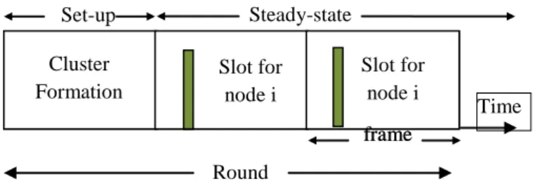
The steady-state operation is broken into frames, where nodes send their data to the cluster head at most once per frame during their allocated transmission slot. The time to send a data frame depends on the number of nodes in the cluster. Figure 2 shows the timeline for one round of LEACH. To reduce energy dissipation, each member node uses power control to set the amount of transmitting power based on the received signal strength of the cluster head advertisement. Furthermore, using a TDMA schedule is an efficient use of bandwidth.
Figure 2: Timeline Showing LEACH Operation
The cluster head must be awake to receive all data from the nodes in the cluster. Once the cluster head receives the data, it performs data aggregation to enhance the common signal. To reduce the possibility of interfering with nearby clusters and reduce its own energy dissipation, each node adjusts the transmit power.
5. Enhancement of Cluster-based Routing Protocol with Parameter Consideration (ECRP-PC) Protocol
In this section, the flow of the proposed system is described and the processes of cluster formation as well as data transmission are explained.
5.1. Proposed System Flow
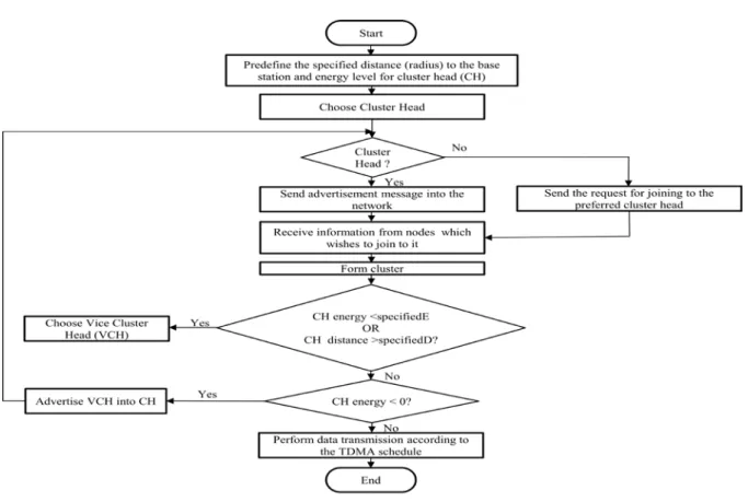
The enhanced LEACH also known as ECRP-PC includes the following steps.
1. The specified distance or predefined radius needs to be pre-assigned before simulation. 2. The cluster head (CH) is selected according to the cluster formation equation.
3. Cluster formation is performed by assigning the cluster head and the member nodes.
4. The assistant cluster head or vice cluster head (VCH) is chosen when the residual energy of the cluster Steady-state Set-up frame Slot for node i Slot for node i frame Slot for node i Slot for node i Time Cluster Formation Round
head is less than the specified energy level or the distance between the cluster head and the base station is longer than the predefined radius.
5. The vice cluster plays the role of the cluster head when the main cluster head dies. 6. The data transmission is performed according the TDMA schedule.
Figure 3: Flow chart of the proposed system
5.2. Cluster Formation
As LEACH protocol chooses cluster head randomly and it does not consider the node residual energy, it may choose the node with lower energy as a CH. If it is, the CH will die early. Hereby, the member nodes in this cluster have no connection to the network to send data to each other. And then, they have to find the next CH to join the network. To avoid choosing the nodes with least residual energy as CH, the proposed ECRP-PC protocol considers the residual energy using equation 4. ECRP-PC forms clusters based on the received signal strength. The CH acts as a router to the sink node to send data. Energy consumption is minimized, as transmission will only be done by CH node. Data fusion and aggregation are local to the cluster. The node chooses a random number between 0 and 1. The node becomes a CH for the current round if the number is less than the following threshold:
𝑇𝑇(𝑛𝑛) =� 𝑃𝑃 1− 𝑃𝑃×�𝑟𝑟𝑟𝑟𝑟𝑟𝑑𝑑1𝑚𝑚�× 𝐸𝐸𝑟𝑟(𝑖𝑖) 𝐸𝐸𝑡𝑡 ,𝑖𝑖𝑖𝑖𝑛𝑛 ∈ 𝐺𝐺 0 ,𝑟𝑟𝑜𝑜ℎ𝑒𝑒𝑟𝑟𝑒𝑒𝑖𝑖𝑒𝑒𝑒𝑒 (4)
where 𝑃𝑃 is the desired percentage of cluster heads, 𝑟𝑟 is the current round, and 𝐺𝐺 is the set of nodes that have not been CHs in the last 1
𝑚𝑚 rounds. 𝐸𝐸𝑟𝑟(𝑖𝑖) is the residual energy of each node and 𝐸𝐸𝑡𝑡 is the total residual energy. In
LEACH protocols, the nodes do not consider the residual energy. ECRP-PC calculates the threshold value by multiplying that of LEACH with the radio of current node residual energy and the total residual energy. This proposed protocol is intended to reduce the number of dead nodes and to extend network lifetime. The average energy consumption for each round is that the total energy consumption is divided by the number of sensor nodes in the network.
5.3. Data Transmission
TDMA schedule is created for all client nodes and is broadcast by CH back to all nodes when CH receives the information from each member node. This schedule is used by all member nodes to transmit their data towards CH. After receiving their TDMA slot information, the nodes begins the process of data transmission. The communication between CH and the member nodes is performed during their assigned time slot. In order to save the energy, each node turns off its radio during unallocated time slots. The nearest nodes to CH use low energy to transmit signal but consumes more energy for the longer distance between the member node and CH. Each node chooses its own transmission energy level, based on Received Signal Strength (RSS) of the CH advertisement message. When a CH receives data from all of its member nodes, compression is performed. After compressing, this data is transmitted towards BS. The operation of ECRP-RE is different from LEACH during the set-up phase. However, they both perform the data transmission in the same manner.
6. Performance Evaluation
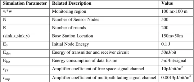
To test the performance of original and proposed protocols, the simulation parameters are defined in Table 1. The simulation is performed in 100m × 100m area and the hundred numbers of nodes are created randomly in this field to cluster the nodes in the network. The base station is located at 150 m and 50 m in the field.
Table 1: Simulation Parameter Setup
Simulation Parameter Related Description Value
w*w Monitoring region 100 m×100 m
N Number of Sensor Nodes 500
R Number of rounds 200
(sink.x,sink.y) Base Station Location 150m×50m
E0 Initial Node Energy 0.1 J
Eelec Energy of transmitter and receiver circuit 50nJ/bit
EDA Energy consumption of data fusion 5nJ/bit/signal
𝐿𝐿𝑓𝑓𝑓𝑓 Amplifier coefficient of free space signal channel 10pJ/bit/m2 𝐿𝐿𝑚𝑚𝑚𝑚 Amplifier coefficient of multipath fading signal channel 0.0013pJ/bit/m4
The sensor nodes are assumed to be stationary for their lifetime. Additionally, at any time, other assumption is that each sensor node is able to compute its residual energy (the remaining energy level).
6.1. Simulation Results
In this section, the simulation results of LEACH protocol and proposed ECRP-PC protocol are examined by measuring the number of alive nodes and total energy consumption. When the number of alive nodes is firstly measured over the number of rounds, ECRP-PC protocol is able to keep alive nodes during the simulation compared to LEACH. This is because ECRP-PC considers the residual energy and node distances when choosing the CH.
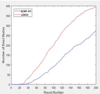
Figure 4 shows the total number of dead nodes depending on 200 rounds. At the beginning, the performance of LEACH and ECRP-PC is almost the same by maintaining the full numbers of alive nodes. The larger the number of rounds, the more increases the number of dead nodes in LEACH. Compared to LEACH protocol, a decrease rate in the number of dead nodes in ECRP-PC is evident than that of LEACH until they reach at the round no-200. Finally, the total number of dead nodes in LEACH protocol is 400 at the last round when that of ECRP-PC is about 260 nodes. In ECRP-PC, the dead node rate is very slower than LEACH. On average, the proposed ECRP-PC reduces significantly the number of dead nodes compared to LEACH.
Figure 4: Comparison of Dead Nodes
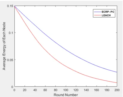
The energy consumption results of LEACH and ECRP-PC are compared based on the round number as shown in Figure 5. The red-colored curve is used to represent the energy consumption of the original LEACH and the blue ones is for the enhanced ECRP-PC. According to the total residual energy, LEACH protocol consumes energy more than the advanced LEACH.
Figure 5: Comparison of Energy Consumption
Energy levels are getting lower for both protocols when the number of rounds is getting higher. On average, the proposed protocol reduces energy consumption about 35% than the original protocol. Therefore, ECRP-PC protocol outperforms than LEACH protocol due to the consideration of parameters such as the node energy and cluster distance or radius centered around the base station. Therefore, ECRP-PC enhanced the original LEACH protocol.
7. Conclusions
In this paper, a proposed ECRP-PC minimizes global energy usage for all nodes to extend the network lifetime due to the fact that the nodes with the highest energy are considered to be CH. Also, it keeps a VCH in a sleep mode as long as CH works fine above a threshold. Due to carefully selection of CH and back up VCH, ECRP-PC thus increases significantly the number of alive nodes compared to LEACH. Considering the residual energy among the nodes and the location of each is effectively able to reduce energy dissipation and enhancing system lifetime of WSNs. Especially, the number of dead nodes is significantly reduced by ECRP-PC about 56% over LEACH in the simulation test.
References
[1] W. Heinzelman, A. Chandrakasan and H. Balakrishnan, “Energy efficient communication protocol for wireless micro sensor networks”, Proceedings of IEEE-HICSS, pp. 1-10, Jan 2000.
[2] W. Heinzelman, A. Chandrakasan and H. Balakrishnan “An application-specific protocol architecture for wireless microsensor networks”, IEEE Transactions on Wireless Communication, Vol. 1, No. 4, pp. 660-670, Oct 2002.
System," in Proceedings of the Aerospace Conference,IEEE, vol. 3, pp. 9-16, 2002.
[4] O. Younis and S. Fahmy, “Heed: A hybrid, energy-efficient, distributed clustering approach for ad hoc sensor networks”, IEEE Transactions on Mobile Computing, Vol.3, No. 4, pp. 366 – 379, Oct 2004.
[5] S. K. Singh, M. P. Singh, and D. K. Singh, “A survey of Energy-Efficient Hierarchical Clustered Routing in Wireless Sensor Networks”, IJANA, vol. 02, pp. 570–580, 2010.
[6] M. F. K. Abad and M. A. J. Jamali, “Modify LEACH algorithm for wireless sensor network”, IJCSI International Journal of Computer Science Issues, Vol. 8, No.1, pp. 219-224, 2011.
[7] R. M. B. Hani and A. A. Ijjeh, “A survey on LEACH-based energy aware protocols for wireless sensor networks”, Journal of Communications, Vol. 8, No. 3, 2013.
[8] A. Ahlawat and V. Malik, “An extended vice-cluster selection approach to improve V-LEACH protocol in WSN”, Third International Conference on Advanced Computing & Communication Technologies, 2013.
[9] G. R. Sharnappa and S. Kannale “Enhanced LEACH multipath based energy efficient routing for wireless sensor network”, International Journal of Advanced Research in Computer and Communication Engineering, Vol. 4, No. 6, 2015.