Degree Programme in Security and Mobile Computing
Shailesh Mota
Secure Certificate Management and
De-vice Enrollment at IoT Scale
Master’s Thesis Espoo, June 30, 2016
Supervisors: Professor Tuomas Aura, Aalto University
Professor Elena Dubrova, KTH Royal Institute of Technol-ogy
Degree Programme in Security and Mobile Computing MASTER’S THESIS Author: Shailesh Mota
Title:
Secure Certificate Management and Device Enrollment at IoT Scale
Date: June 30, 2016 Pages: 77
Major: Security and Mobile Computing Code: T3011 Supervisors: Professor Tuomas Aura
Professor Elena Dubrova
Instructor: Rajat Kandoi M.Sc. (Tech.), Ericsson, Finland
The Internet of Things (IoT) is expected to comprise of over 20 billion devices connected to the Internet by the year 2020, and support mission critical appli-cations such as health care, road safety and emergency services to name a few. This massive scale of IoT device deployment, heterogeneity of devices and appli-cations, and the autonomous nature of the decision making process introduces new security requirements and challenges. The devices must be securely boot-strapped in to the network to provide secure inter–device communication and also, the applications must be able to authenticate and authorize these devices to provide the relevant services.
In today’s Internet, Public Key Infrastructure (PKI) is widely used to provide au-thenticity, encryption and data integrity during network communication through the use of digital certificates. This thesis investigates the key aspects for deploying a PKI security solution in an IoT ecosystem, ranging from deploying certificates on new devices (bootstrapping) to complete life cycle management of these cer-tificates. We believe that the current PKI can be, with suitable enhancements, used to provide the efficiency, scalability and flexibility needed for IoT security. This thesis provides a survey of key aspects for deploying PKI security solution in IoT ecosystem. We investigate different certificate management protocols and motivate the applicability of enhanced security over transport (EST) protocol for IoT PKI solution. In addition, we propose a PKI deployment model and the bootstrap mechanism to bring up an IoT device and provision it with a digital certificate. Furthermore, we provide a prototype implementation to demonstrate certificate enrollment procedure with an EST server.
Keywords: IoT, PKI, EST, bootstrapping Language: English
Utbildningsprogrammet f¨or s¨aker och mobil kommunikation DIPLOMARBETET Utf¨ort av: Shailesh Mota
Arbetets namn:
S¨akra Certifikathantering och Device Inskrivning p˚a sakernas Skala Datum: Den 30 Juni 2016 Sidantal: 77 Huvud¨amne: S¨aker och mobil kommunikation Kod: T3011
¨
Overvakare: Professor Tuomas Aura Professor Elena Dubrova
Ohjaaja: Rajat Kandoi M.Sc. (Tech.), Ericsson, Finland
Sakernas Internet (IoT) f¨orv¨antas best˚a av mer ¨an 20 miljarder enheter som ¨
ar anslutna till Internet ˚ar 2020, och st¨odja verksamhetskritiska applikationer s˚asom h¨alsov˚ard, trafiks¨akerhet och r¨addningstj¨ansten f¨or att n¨amna n˚agra. Den-na massiva omfattningen av sakerDen-nas enhet drifts¨attning, heterogenitet enheter och applikationer, och den sj¨alvst¨andiga karakt¨aren av beslutsfattandet inf¨ors nya s¨akerhetskrav och utmaningar. Produkterna skall vara s¨akert stroppad in p˚a n¨atet f¨or att ge s¨aker inter - enhet kommunikation och ¨aven m˚aste ans¨okningarna kunna autentisera och auktorisera dessa enheter f¨or att tillhandah˚alla de aktuella tj¨ansterna.
I dagens Internet, ¨ar Public Key Infrastructure (PKI) anv¨ands i stor ut-str¨ackning f¨or att tillhandah˚alla ¨akthet, kryptering och dataintegritet un-der n¨atverkskommunikation genom anv¨andning av digitala certifikat. Denna avhandling unders¨oker de viktigaste aspekterna f¨or att distribuera en PKI s¨akerhetsl¨osning i ett sakernas ekosystem, fr˚an distribuera certifikat p˚a nya en-heter (bootstrapping) f¨or att slutf¨ora livscykelhantering av dessa certifikat. Vi anser att den nuvarande PKI kan vara, med l¨ampliga f¨orb¨attringar, som anv¨ands f¨or att ge effektivitet, skalbarhet och flexibilitet som kr¨avs f¨or sakernas s¨akerhet. Denna avhandling ger en ¨oversikt ¨over de viktigaste aspekterna f¨or distribution PKI s¨akerhetsl¨osning i sakernas ekosystem. Vi unders¨oker olika protokoll certifikat f¨orvaltning och motivera till¨ampligheten av f¨orb¨attrad s¨akerhet ¨over transporter (EST) protokoll f¨or sakernas Internet PKI-l¨osning. Dessutom f¨oresl˚ar vi en PKI distributionsmodell och bootstrap mekanism f¨or att ta upp en sakernas internet enheten och tillhandah˚allandet det med ett digitalt certifikat. Dessutom erbjuder vi en implementering prototyp att visa certifikatregistreringsf¨orfarande med en EST-server.
Nyckelord: IoT, PKI, EST, bootstrapping Spr˚ak: Engelska
I will like to acknowledge my supervisors for their guidance, motivation and support. The thesis is an outcome of the research insights provided by Pro-fessor Tuomas Aura. The discussions with ProPro-fessor Tuomas were highly constructive and drove the thesis to its conclusion. Professor Elena Dubrova provided useful tips for finalising the structure of the thesis. I will like to thank my friend and instructor Rajat Kandoi for highly productive brain-storming and cooking sessions. Moreover, I will like to thank Jeanne for keeping me motivated to finish the work in time. Finally, thanks to my parents for their continuous support and belief in me.
Espoo, June 30, 2016 Shailesh Mota
3GPP 3rd Generation Partnership Project
6LoWPAN IPv6 over Low power Wireless Personal Area Net-works
ASN.1 Abstract Syntax Notation One CA Certification Authority
CBOR Concise Binary Object Representation CMP Certificate Management Protocol
CMC Certificate Management Messages over CMS CMS Content Management System
CoAP Constrained Application Protocol CP Certificate Policy
CRL Certificate Revocation List
CRMF Certificate Request Message Format CSR Certificate Signing Request
DAD Duplicate Address Detection DER Distinguished Encoding Rules
DHCPv6 Dynamic Host Configuration Protocol Version 6 DN Distinguished Name
DNS Domain Name System
DNSSL DNS search list
DTLS Datagram Transport Layer Security ECC Elliptic Curve Cryptography
EST Enrollment over Secure Transport FTP File Transfer Protocol
HTTP Hypertext Transfer Protocol
IEC International Electrotechnical Commission IETF Internet Engineering Task Force
IKE Internet Key Exchange IoT Internet of Things
JAX-RS Java API for RESTful Web Services
MHT Merkle Hash Tree
MIME Multipurpose Internet Mail Extensions NGE Next Generation Encryption
NI Node Information
NIST National Institute of Standards and Technology OCSP Online Certificate Status Protocol
OWHF One Way Hash Funtions PGP Pretty Good Privacy PKI Public Key Infrastructure PoP Proof Of Possession PSN Public Services Networks PTC Positive Train Control RA Registration Authority RA Router Advertisement RDI Revocation Data Issuer
REST Representational State Transfer RPKI Resource Public Key Infrastructure SCEP Simple Certificate Enrollment Protocol
SCP Secure Copy
SCT Signed Certificate Timestamp STH Signed Tree Hash
TCP Transmission Control Protocol TLS Transport Layer Security UDP User Datagram Protocol VPN Virtual Private Network XML Extensible Markup Language
Abbreviations and Acronyms 5
1 Introduction 9
1.1 Problem statement . . . 9
1.2 Motivation . . . 10
1.3 Contribution . . . 10
1.4 Structure of the Thesis . . . 11
2 Background on Public Key Infrastructure 12 2.1 Roles in PKI model . . . 13
3 Background on Certificate Management Protocols 15 3.1 SCEP . . . 16
3.1.1 SCEP based certificate enrollment . . . 17
3.2 CMP . . . 18
3.3 CMC . . . 21
3.4 EST . . . 22
3.4.1 Operational Scenarios in EST . . . 23
3.4.2 Comparison of EST with SCEP . . . 25
3.4.3 Comparison of EST with CMC and CMP . . . 26
3.4.4 Adoption of EST . . . 27
3.4.5 Potential Use Cases of EST . . . 28
4 Security in IoT devices 29 4.1 Internet of Things market potential . . . 29
4.1.1 Deployment Scenarios with IoT . . . 30
4.1.1.1 Automotive . . . 30
4.1.1.2 Health–care . . . 31
4.1.1.3 Smart–cities . . . 31
4.1.1.4 Intelligent Transportation Systems . . . 32
4.1.1.5 IoT utilities . . . 32
4.3 PKI as a security solution for IoT . . . 36
4.3.1 Security protocols in IoT protocol stack . . . 37
4.3.2 PKI consideration for IoT . . . 37
5 Naming of IoT Devices 40 5.1 DNS name auto–configuration for IoT devices . . . 40
6 Certificate Management with Merkle Hash Trees 43 6.1 Merkle Hash Tree . . . 44
6.2 Certificate Transparency . . . 46
7 Bootstrapping IoT Device 49 7.1 IoT deployment model . . . 49
7.2 Bootstrapping Procedure . . . 50
8 Implementation and evaluation 52 8.1 CoAP . . . 52
8.2 Tools used . . . 54
8.3 EST server prototype . . . 55
9 Discussion 58 9.1 PKI challenges for IoT . . . 58
9.2 Certificate Transparency with IoT PKI . . . 59
9.3 Future work . . . 59
10 Conclusion 60 A First appendix 72 A.1 Types of PKI model . . . 72
A.1.1 A single CA or monopoly model . . . 72
A.1.2 A single CA with RA model . . . 73
A.1.3 Oligarchy CA model . . . 73
A.1.4 Configured plus Delegated CA model . . . 74
A.1.5 Anarchy model . . . 76
A.2 IoT economic impact . . . 76
Introduction
The Internet of Things (IoT) is a growing network of embedded autonomous devices or sensors with an IP address for Internet connectivity. The inter-connected system between IoT and other Internet capable system promises improved quality of life, increased efficiency and greater economic growth. Gartner’s recent reports on IoT devices indicate that there are more than 3 billion IoT devices available in the smart environment at present and there is a continuing interest in the market towards adoption of IoT devices. How-ever, Cyber threats are prevalent against IoT deployments, the number of attacks and tools available to potential attackers are becoming more efficient. This rise in the number of connected devices has created a pressing demand for robust security and authentication mechanisms. The thesis focuses on establishing trust across connected devices in large scale IoT deployments.
1.1
Problem statement
The rise in the number of connected IoT devices has lead to increase in the challenges to secure inter–device communication. Moreover, recent attacks on IoT environments demonstrate a lack of generic security architecture in operation of IoT devices. Public key infrastructures (PKI) is the trusted se-curity framework which provides authenticity, encryption and data integrity to secure current Internet. In this thesis, we answer the question “What are the various aspects to deploy a flexible, scalable, efficient and trustworthy PKI for IoT environment ?”. We investigate key aspects, challenges and the importance of deploying a PKI security solution for IoT ecosystem both from a theoretical and an engineering perspective.
1.2
Motivation
The work done in this thesis is motivated by the following factors :
1. Certificate management protocols facilitate PKI operations such cer-tificate enrollment and revocation, private key generation, key renewal and update. It is worth investigating the various existing certificate management protocols and choosing the suitable for IoT device de-ployment scenario.
2. Cyber threats are prevalent against IoT deployment scenario leading to disabling of system operation, economic loss and threat to privacy of sensitive user data. It is worth reviewing security attacks on various IoT deployment scenarios.
3. PKI is designed to provide secure communication between client–server architecture of current Internet. It is important to understand differ-ent challenges and aspects to adopt PKI solution for providing secure communication in IoT deployment scenario.
4. Certificate management system employed for PKI in IoT deployments should support billions of certificate operations. It is significant to examine a scalable data structure solution to support certificate oper-ations.
5. Certificate provisioning addresses identification of devices based on dig-ital certificates. It is appropriate to investigate different aspects for bootstrapping an IoT device to provision it with a digital certificate. 6. Compromised certificate authority (CA) can end–up issuing
unautho-rised SSL certificates. This way an attacker can impersonate a web server and extract sensitive user data. It is worth studying how ex-isting solutions can be used to introduce trustworthiness of CAs by making CA operations transparent in a PKI deployment.
1.3
Contribution
This thesis provides a survey of the key aspects and the importance of de-ploying a PKI security solution for IoT ecosystem. We examine various ex-isting protocols and mechanisms for certificate management including SCEP, EST, CMC and CMP. We propose the use of EST protocol for secure cer-tificate provisioning of IoT devices. Further, we motivate the applicability
of EST protocol for resource constrained environments. We identify various challenges in deploying PKI solution for IoT environment. Furthermore, we discuss various cyber attacks against IoT deployment scenario leading to dis-abling of system operation, economic loss and threat to sensitive user data. Moreover, we propose a PKI deployment model for IoT environment and the bootstrap mechanism to bring up an IoT device and provision it with X.509 digital certificate which ensures device authenticity, data confidentiality and integrity. In addition to the literature survey, we provide a proof-of-concept implementation which demonstrates certificate enrollment procedure with an EST server.
1.4
Structure of the Thesis
The rest of the thesis is organized as follows: Chapter 3 provides the back-ground information about certificate management protocols including SCEP, EST, CMC and CMP. We motivate the adoption of EST protocol for re-source constrained environments. Chapter 4 provides details on different IoT deployment scenarios and reviews recent attacks in IoT environments. Furthermore, we investigate various challenges and aspects to be considered in deploying PKI solution for IoT environment. Chapter 5 examines different schemes for naming and identification of IoT devices. Chapter 6 gives neces-sary details about merkle hash trees (MHT) which is a scalable data structure solution to support certificate operations performed by a CA. Chapter 7 con-tains our proposal for the bootstrap mechanism to bring up an IoT device and provision it with digital certificate. Chapter 8 explores application layer protocol used in resource–constrained environments. In addition, we demon-strate a prototype implementation for certificate enrollment procedure with an EST web–server. Chapter 9 discusses the feasibility of applying certificate transparency to increase the trustworthiness of CA operations. Chapter 10 summarizes the thesis and provides concluding remarks.
Background on Public Key
In-frastructure
PKI is a model wherein a set of roles, policies and procedures are needed for the creation, management, storage and revocation of digital certificates to facilitate public–key encryption [106]. The main purpose of PKI model is to enable secure communication between different entities involved in net-work activities. Some such activities are e–commerce, Internet banking and secure electronic mail. PKI plays a critical role in secure communication where password based authentication methods are not sufficient and a more thorough procedure is required to confirm the identities of communication parties and validation of information transferred over the network.
PKI is built on public key cryptography and digital certificates. It is an arrangement which binds the public key with the identities of different network entities such as a user, client machine or a server. The binding pro-cedure is established with the help of a CA. CA is responsible for registration and issuance of digital certificates for the requesting clients or network enti-ties. This in–turn allows clients to learn the public keys of other clients and hence, communicate securely.
To illustrate this, we assume there are two network entities Alice and Bob who want to securely communicate with each other. The CA is considered to be a trusted node which has a self-signed digital certificate. Furthermore, digital certificate is a data structure which binds name with public key. In this scenario, if Bob trusts a particular CA and has the public key of the CA he can further securely know the public key of Alice. To achieve this Bob has to obtain a digital certificate signed by the CA that certifies the public key of Alice. In some scenarios, Bob may not be pre–configured with the public key of CA that certified Alice’s public key, hence, Bob has to obtain a chain of certificates. For example, Bob knows the public key of CA1 and hence
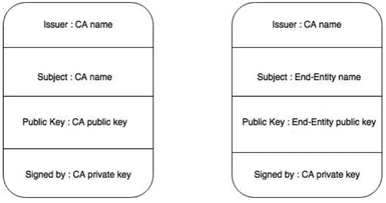
Figure 2.1: Fields in a digital certificate.
trusts CA1. Alice’s public key is signed by CA3. CA3’s public key is signed by CA2 and CA2’s public key is signed by CA1 [89]. Once Bob obtains this chain of certificates from Alice he can trust the public key of Alice and start secure communication with her.
Figure 2.1 depicts the fields and the values used in a digital certificate. Every CA has a self-signed certificate, hence, the issuer and subject fields of certificate have the same value which is the distinguished name of the CA. Public key field has the public key of the CA and the certificate is signed using the private key of the CA. Any client certificate issued by a CA has the distinguished name of the client in the subject field and the issuer field has CA’s distinguished name. The public key of the client is inserted in the public key field and the certificate is signed with the private key of the CA.
2.1
Roles in PKI model
In a generic PKI model there are multiple entities involved. Below we de-scribe different roles in a PKI model [30, 64]:
1. Certificate Authority (CA) : The CA is responsible for storing, issuing and digitally signing the certificates.
2. Registration Authority (RA) : The RA is responsible for verifying the identity of entities requesting a digital certificate from a CA. The RA is responsible for forwarding the issuance request to the CA.
3. Central directory : A secure database or repository for storing and indexing keys.
4. Certificate Policy (CP) : A CP is a document stating different roles and duties of a PKI. In case of X.509 digital certificates, a specific field can be set to indicate associated CP [34]. This value indicates the assurance level associated with a certificate. Hence, any relying party can decide the level of trust to put in the certificate.
5. Certificate management system (CMS) : A CMS is used for perform-ing tasks such as managperform-ing access to stored certificates and deliverperform-ing certificates to be further issued to the requester [74].
Background on Certificate
Man-agement Protocols
PKI is widely used to authenticate the identity of end–points such as users, devices and applications in the form of digital certificates. Digital certificates are being increasingly deployed, X.509 certificates [36] serve as the basis for authentication in the Internet Engineering Task Force (IETF) standards such as The Internet Key Exchange (IKE) [52] and IKEv2 [60], Virtual Private Networks (VPNs) [27] and Transport Layer Security Protocol (TLS) [38, 39, 41]. A CA needs a certificate issuance mechanism or a protocol for granting X.509 certificates to the end–points. Such protocols fall under the category of certificate management protocols. Through certificate management protocols a PKI client can issue requests such as certificate issuance, certificate renewal, certificate revocation, etc., to the CA. Moreover, the protocol enables PKI client to request certificate revocation status information. However, this functionality is also distinctly provided by mechanisms such as certificate revocation lists (CRLs) [114] and online certificate status protocol (OSCP) [82].
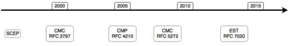
Through the efforts of IETF PKI X.509 working group two certificate management protocols have been developed – Certificate Management Pro-tocol (CMP) [98] and Certificate Management Messages over CMS (CMC) [26]. Both the protocols offer essentially the same basic functionality de-scribed in Section 3.2 and Section 3.3. However, CMP is more comprehen-sive and widely deployed [15] of the two. Moreover, over the years Cisco has developed two other protocols – Simple Certificate Enrollment Protocol (SCEP) [51] and Enrollment over Secure Transport (EST) [90]. EST and SCEP facilitate certificate provisioning and enrollment. SCEP is the evolu-tion of enrollment protocol which is widely supported in both client and CA implementations.
Figure 3.1: Time-line showing certificate management and certificate enroll-ment standards over the years.
Figure 3.1 shows the time–line for creation of the aforementioned stan-dards.
3.1
SCEP
SCEP is a PKI communication protocol which utilizes PKCS#7 and PKCS#10 messages that are sent over Hypertext Transfer Protocol (HTTP). It is the most widely deployed protocol for certificate requests and CRL queries. How-ever, the protocol does not support certain certificate management features such as in-band certificate revocation transactions. To support more compre-hensive functionality the IETF protocol suite provides two other certificate management protocols – CMP and CMC. SCEP is not a formal standard or RFC; it is a draft which has already expired and has been published as historic. The protocol supports operations such as public key distribution through CA and RA, certificate enrollment, certificate query and CRLquery [51].
The SCEP draft defines the following entity types :
1. Requester : The requester is the client or end-point for SCEP message exchange. It is allowed to submit SCEP messages for itself or on behalf of peers. Before starting a PKI transaction, a requester is required to have an appropriate RSA key pair. This key is used for signing the SCEP pkiMessage to be sent to the server. SCEP message types are based on PKCS#7 [59] and PKCS#10 [85]. Moreover, a requester must locally configure the IP address or domain name of the CA server and identity information to be used for authentication of the CA.
2. SCEP CA : A SCEP CA is responsible for signing the client certificates. The issuer field of the certificate is set with the name of issuing CA. Before any PKI transactions can begin, the SCEP CA server obtains a CA certificate which can be self–signed or issued by a higher level CA. This certificate is provided out–of–band to the SCEP requester.
To authenticate the CA certificate the requester can use the fingerprint information in the CA certificate which is obtained after sending a Get-CACert message. The CA is responsible for answering the CRL queries of the requester and must include CRLDistributionPoint information in the certificates it issues. Moreover, the CA server must be a high– availability service for answering CRL queries itself. The CA can also make the certificates available through LDAP [103]. Furthermore, the CA can also enforce policies on the client requests, reject client requests and return previously created certificates for duplicate requests. 3. SCEP RA : SCEP RA server performs authorization and validation
checks for the SCEP requester on behalf of CA server. After receiv-ing a GetCACert message from the requester, RA performs validation checks on the request and forwards the certification requests to the CA. Moreover, the RA certificate is also included in the response to Get-CACert message indicating the existence of the RA to the requester. Communication between RA and CA server can be carried out with SCEP messages or other protocols such as CMC [26].
3.1.1
SCEP based certificate enrollment
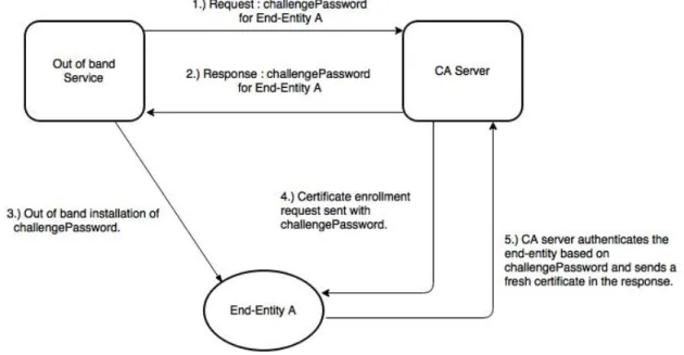
The certificate enrollment request from the requester has to be authenticated by the CA/RA server before a new certificate can be issued. The SCEP pro-tocol uses public-key cryptography to associate public keys and the identity of the requester. This prevents a man–in–the–middle attack and the data between the requester and CA is secured. The communication is secured by using SCEP secure message objects which specifies how PKCS#7 [59] is used for encryption and signing the messages. To perform signing, the requester uses a local certificate obtained from an alternate CA. The CA server may accept or reject the request by looking up at the policy settings . Moreover, the requester can also locally generate a self-signed certificate to perform the signing operation. The SCEP draft does not support client authentica-tion based on a self–signed certificate. Requester authenticaauthentica-tion can also be performed by utilizing challengePassword attribute which is sent as part of the enrollment request by the requester. This attribute has been specified as part of PKCS#9 standard[86]. The challengePassword is a shared secret distributed privately (only known to the requester) by the CA server. This attribute uniquely associates an enrollment request with the requester [51].
Figure 3.2 demonstrates certificate enrollment by utilizing challengePass-word attribute in SCEP. The SCEP CA server does not support certification revocation requests from the requester. Certificate revocation requests can
Figure 3.2: Messages exchanged during certificate enrollment in SCEP.
be performed using other certificate management protocols such as CMP and CMC.
3.2
CMP
CMP is a PKI communication protocol used by end–entities to obtain X.509 digital certificates from the CA server. CMP request and response messages are encoded in Abstract Syntax Notation One (ASN.1) using Distinguished Encoding Rules (DER) method. CMP messages are generally encapsulated over HTTP. Other possible means of transport to carry CMP messages are transmission control protocol (TCP) or any connection-oriented transport protocol such as a file over file transfer protocol (FTP) or secure copy (SCP) and through e–mail using multipurpose internet mail extensions (MIME) encoding standard. CMP uses application/pkixcmp as the content–type [61]. Through CMP, an end–point can communicate with the CA server to request, revoke, suspend and resume digital certificates. Any number of RAs can be present to mediate the request–response messages between the CA and the end–point.
End–entity certificate request messages need to be authenticated to the CA or RA server. This is know as end–entity message origin authentication.
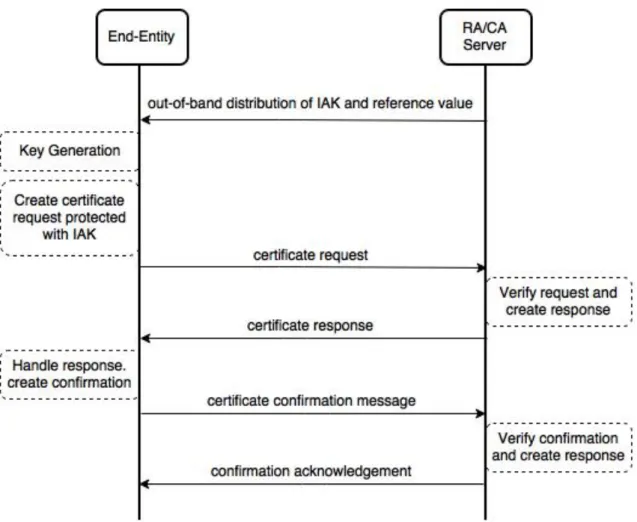
Figure 3.3: Message flow during a certificate request with CMP.
To achieve this the CA or the RA server issues the end–entity with a secret known as initial authentication key and a reference value which is used to identify the initial authentication key. Further, the initial authentication key is used to protect relevant PKI messages [98].
Figure 3.3 demonstrates a scenario where an end–entity initiates a new certificate request from the CA server. In this scenario, message authenti-cation of the end–entity is required, key generation occurs at the end–entity and a confirmation message is sent by the end–entity after the completion of the transaction.
In case, the verification of confirmation message fails at RA or CA server, the newly issued certificate is revoked immediately.
1. Root CA Initialization : A new root CA produces a self–certificate with the fingerprint. Further, using out–of–band means the end–entities acquire the fingerprint securely and can verify the self–certificate of the newly created root CA.
2. Root CA Key Update : This operations supports periodically updating CA keys.
3. End Entity Initialization : To initialize end–entities two steps are nec-essary. First, acquiring PKI information. Secondly, verifying public key of root CA. Verification is performed out–of–band.
4. Subordinate CA Initialization : The initialization of a subordinate CA is similar to end–entity initialization. However, the subordinate CAs are also updated with the revocation lists.
5. CRL production : A newly set–up CA must periodically produce ver-sions of each CRL.
6. PKI Information Request : This operation enables PKI entity (CA, RA or an end–entity) to acquire all the information about current status of a CA.
7. Cross Certification : To accomplish this operation the requester CA becomes the subject of the cross–certificate and the responder CA be-comes the issuer.
8. Certificate Request : After the end–entity is initialized, it requests the CA for a certificate with a certification request (cr) message. The CA responds back with a newly created certificate after authenticating the end–entity.
9. Key Update : This operation enables an end–entity to request an up-date for an expiring key pair. The end–entity can send upup-date requests to the CA to issue a new certificate for a new key pair or for the same key pair. The CA returns the new certificate in a key update response message.
10. Revocation operations : Scenarios such as certificate forging require revocation of the forged certificate. In this case, an authorised entity can send a revocation request to the CA server.
3.3
CMC
CMC is a certificate management protocol which is based on the existing cryptographic message syntax (CMS), PKCS#10 [58] and certificate request message format (CRMF) [97] specifications. CMC introduces a way of per-forming enrollment operations within a single round trip unlike CMP pro-tocol. The protocol is designed such that the key generation occurs at the end–entity. CMC supports all the mandatory algorithms cited by S/MIME standard [91]. Moreover, CMC also supports operations such as transac-tion management, replay detectransac-tion through tokens, deferred and pending responses to enrollment requests which requires external methods for issu-ing a certificate. Transport mechanisms exercised within CMC specification such as HTTP, FTP, SCP, e–mail or TCP are defined in [99]. Architecturally CMC is similar to SCEP, however, the specification supports more options and implements greater algorithmic agility. CMC defines message formats, message control, and data structures for supporting wider range of certificate management operations in comparison to certificate provisioning operations supported by SCEP [26].
An enrollment transaction in CMC is generally completed within a single round–trip. An end–entity sends a PKI enrollment request to the CA server and obtains a PKI enrollment response from the CA. Some exceptional cases such as delayed certificate issuance require more than one roud–trip time. CMC protocol defines two types of PKI requests and responses which are formed using PKCS#10 or CRMF structures [99]:
1. Simple PKI Request: This request if formed using the bare PKCS#10 structure.
2. Full PKI Request: This request consists of more than one PKCS#10 or CRMF messages structures encapsulated in a CMS as part ofPKIData. The two types of PKI Responses are based on SignedData or Authenti-catedData message structures :
1. Simple PKI Response: This response is a certs-only SignedData. 2. Full PKI Response: This response consists of content type
PKIRe-sponse wrapped in a SignedData message structure.
In CMC, RAs participate in the protocol by wrapping the end–entity PKI requests in another layer of PKI request and forwarding the expanded request to the CA server. Moreover, the CAs and RAs require the client to include
a proof–of–identity with the certification request. In CMC, the proof–of– identity is based on a shared secret between the client and CA/RA server. The shared–secret is a series of tokens which can be generated separately through a dedicated hardware device. The end–entity usually proves its identity by transferring this token in plain text along with a string identifier. Moreover, CMC also provides renewal and re–keying mechanisms. These requests are similar to any certification request wherein the end–entity needs to provide an identity proof such as existing certificates from another trusted CA [26].
Both CMC and CMP provide similar basic functionality for management of certificate life–cycle for PKI entities. CMP extensively reuses the existing CMS code which enables faster and efficient implementation of the protocol. CMP offers some additional functionality over CMP such as direct transfer of trusted root CA certificates to the end-entity. In terms of maturity level, deployment and interoperability CMP scores over CMC. Currently, CMP is supported in most of the PKI/CA products, offers extensive industry–wide interoperability and has been tested thoroughly in multi–vendor PKI envi-ronments. Due to the lack of implementations, CMC has not gone through extensive industry–wide testing and hence, will take more years to reach the stability and interoperability status offered by CMP [15].
3.4
EST
EST is a new protocol developed by Cisco to facilitate the life–cycle man-agement of digital certificates. EST uses PKCS#10 and CMS for generating certificate requests and definitions. Moreover, the implementation is avail-able as an open–source library developed by Cisco as libEST [21]. EST utilizes Cisco’s Next Generation Encryption (NGE) by using Elliptic Curve Cryptography (ECC) instead of RSA encryption supported in SCEP. NGE provides high level of security and scalability through a set of algorithmic suites for authenticated encryption, elliptic-curve based digital signatures and key establishment, and cryptographic hashing. Both EST and SCEP facilitate certificate provisioning with the aim to provide certificates to the end points from a CA/RA server. However, these protocols do not aim at solving certificate management issues. Certificate management is handled separately through CMC and CMP [22].
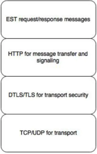
Figure 3.4 depicts the protocol stack used by EST protocol for message transfer.
Figure 3.4: Protocol layers used with EST.
3.4.1
Operational Scenarios in EST
Prior to initiation of requests/response messages, the EST clients and server are configured with information to support mutual authentication and au-thorization. This information can be in the form of shared secrets, network service names, trust anchor information, enrollment keys, etc,. Moreover, based on the network management practices in an enterprise the client’s might be pre–installed with trust anchors through an out–of–band secured procedure.
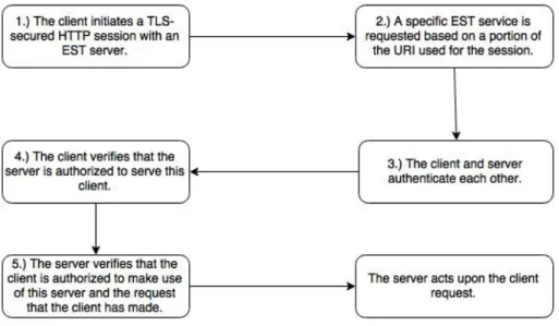
Figure 3.5 shows the general client–server interaction flow. Below we describe the operational scenarios with EST protocol in detail [90] :
1. Retrieving CA Certificates : Before performing any operation, the EST client requests a copy of EST CA certificates from the EST server. EST CA uses this certificate to sign objects that are being issued to the EST client such as certificates and CRLs. In order to authenticate and verify the authorization scope of the EST server the client can use different options including implicit trust anchor database, previously distributed trust anchor specific to the EST server, manual authenti-cation performed by network administrator or a certificate–less TLS authentication based on a shared–secret specific to the EST server. 2. Initial enrollment of the client : After the client has authenticated an
EST server, it can acquire a certificate by submitting an enrollment request to the EST server. Further, the EST server authenticates and
Figure 3.5: EST client and server interaction flow.
authorizes the EST client using different options such as TLS based authentication using vendor installed client certificate, certificate is-sued by other CAs or existing client certificate isis-sued by the same EST server. Moreover the EST server can also perform certificate–less TLS authentication based on a shared–secret or HTTP–based authentica-tion with username and password distributed out–of–band.
3. Certificate Signing Request (CSR) attribute request : An EST client can query the EST server for additional attributes before sending an enrollment request. These attributes are helpful in providing additional descriptive information to the EST server and the client. Information such as media access control (MAC) address of client interface, cryp-tographic hash function and encryption algorithm to be used can be obtained using a CSR request.
4. Re–issuance of client certificate : An EST client submits a re–enrollment request to renew its existing certificate. To authenticate itself the client can produce the existing certificate to the EST server or leverage any of the methods used for authentication during initial enrollment. 5. Server Key Generation : With the EST protocol the client can request
the server to generate a key pair. The server is responsible for imple-menting appropriate random number and key generation as per [44]. Moreover, a CA policy determines the archiving of client key pair which
is sent to the client over a secure TLS session.
3.4.2
Comparison of EST with SCEP
EST is the recommended protocol for certificate provisioning over SCEP for the following reasons [22]:
1. SCEP messages are sent over HTTP using pkiMessage. To secure the
pkiMessage, the messages are are enveloped in pkcsPKIEnvelope en-velopes. However, EST employs Transport Layer Security (TLS) for secure transport of certificates and messages. This way there is no need to envelop the messages.
2. In case of SCEP, the certificate signing request (CSR) is authenticated through a shared secret between the client and the CA. Since EST uses TLS, the requester of a CSR is pre–authenticated and trusted, hence, the CSR is always tied to the requester. The method employed in SCEP introduces a security concern.
3. Within the PKI ecosystem, it is necessary to support automated cer-tificate renewal and re-enrollment. The previous implementations of SCEP did not deploy such messages, however, recently submitted drafts of SCEP have added the support for automatic renewal and re–enrollment of certificates. In case of EST, automated certificate renewal and re-enrollment messages are built–in with the standard.
4. EST has also added server–side key generation through an enrollment request by the requester. In case of SCEP only private key generation at the client side is supported. Within resource constrained environments or devices server–side key generation can be an important aspect as they do not have enough entropy source and power for generation of a random private key.
5. As a standard SCEP was formulated in 1990s and did not receive wide community scrutiny during the development phase in IETF. EST was developed as a standard with the joint efforts of vendors and stan-dards community and has received wide community scrutiny through-out the development phase. Moreover, Cisco has provided an open– source implementation of EST standard which is useful for vendors and researchers to experiment with.
6. EST supports CA rollover for refreshing trust anchors installed on the EST clients. To accomplish CA rollover, EST uses three certificates
during the transition period. Hence, all the PKI entities can be rolled to the new CA without affecting communication between the PKI entities involved. However, CA rollover with SCEP is less flexible and lacks automation. SCEP does not have a transition period for CA rollover instead it requires a flag day.
EST provides significant security improvements over SCEP in the follow-ing ways :
1. With EST the certificate signing request is tied to a requester which is authenticated with TLS. Hence, the certificate is rendered only to the requesting entity. The requesting entity holds a private key or a user– name and password. The user–name and password acts as a proof of possession (PoP). By enforcing PoP, requesting entities or clients can not forge a certificate for other clients. However, with SCEP a CSR is authenticated using a shared secret between a client and CA. This introduces a security vulnerability in real–world deployments. Any client with an access to the shared secret can generate a CSR for other clients. Moreover, the shared secret is not a onetime secret for each client, hence, it further complicates the distribution of a shared secret. 2. Over the years, TLS protocol has been continuously improved and its security has been proven. This ensures that EST messages are secured. However, SCEP is tightly coupled with RSA to provide data protection which introduces security concerns with technological advancements. 3. EST offers better cryptographic agility than SCEP by supporting ECC
as a secure cryptographic algorithm for encryption. ECC is computa-tionally efficient and better suited to the needs of resource–constrained environments. SCEP uses PKCS#7 methods based on RSA encryp-tion.
3.4.3
Comparison of EST with CMC and CMP
CMC and CMP protocol support to certificate management including certifi-cate enrollment, certificertifi-cate status, certificertifi-cate revocation, etc,. EST certifi-caters to certificate provisioning, hence, it can be considered as a profile of CMC that uses a secure mode of transport for key enrollment and renewal. In case of CA certificate rollover, EST follows CMP standard. In brief, CMC and CMP were defined as two standards with common goal within a short time frame by IETF. However, both the standards have to failed to gather mainstream acceptance as they are complicated to implement.
1. To define the ways of processing control data CMC uses multiple wrap-pings of CMS messages and Abstract Syntax Notation (ASN.1) struc-tures. CMP incorporates enveloped message data for control data pro-cessing. However, the messages in EST are simple and lightweight. 2. EST incorporates TLS for secure transmission of messages.
3. With an enrollment request a server–side key can be generated in EST standard. Moreover, the private key for client can be securely trans-ferred with TLS without the need of further encryption. This can be a vital step in case of Resource Public Key Infrastructure (RPKI) or low power devices which do not have enough entropy for generating a random private key. Server–side key generation is not included in CMP standard. Moreover, CMC does not address server–side key generation operation.
4. EST supports the renewal of CA certificates by combining renewal messages defined in CMP with the CMC specification. However, CMC does not support the renewal of CA certificates.
3.4.4
Adoption of EST
SCEP has been supported as an industry wide standard in vendor products for more than 15 years. It is included in many standards and all the CAs sup-port it. However, the limitations of SCEP are distinguishable with resource constrained devices as described in the Section 3.4.2. CMP has been made mandatory by the 3rd Generation Partnership Project (3GPP) as part of TS 33.310 standard. However, as a part of TS 33.310 standard the utilization of CMP is limited to provisioning. Moreover, CMP is also included in the National Institute of Standards and Technology’s (NIST) Special Publication 800-57. Further, CMP and CMC are also supported by some of the CA ven-dors and PKI products. The latest EST standard is used in IETF ANIMA WG‘s bootstrapping drafts. Moreover, Wi–Fi alliance has mandated the use of EST in hot–spot 2.0. Additionally, to address security concerns within power systems the International Electrotechnical Commission (IEC) created IEC 62351. IEC also mandates the use of EST as a certificate provisioning protocol. Currently, multiple CA vendors are adding support for EST such as Cisco‘s IOS and IOS-XE product [22].
Amongst the available protocols for certificate provisioning EST stands out for its simplicity, open–source development and advantages it provides over the other protocols. The open–source implementation in the form of a portable library is easy to use and promotes quicker adoption and increases
interoperability of EST into more vendor products. As per Industry Trade Association for Public Services Networks (PSN), “Cisco’s release of its EST code into the open source community will facilitate rapid adoption by the PSN community. With the release of this code, other vendors will be able to accelerate their adoption of EST and this in turn expands the choice of encryption solutions available to public sector organizations” [16].
3.4.5
Potential Use Cases of EST
EST can be effectively deployed in a variety of use–case scenarios. One such scenario can be an enterprise with numerous network end–points which re-quire periodic certificate renewal. In case of enterprise server’s certificate expiration, EST offers automatic re–enrollment for obtaining new certificate. Subsequently, speeding up the entire procedure and this requires no manual intervention from network administrator. Moreover, EST also supports auto-matic redistribution of updated CA certificates. The future IoT environment is bound to support large number of end–points giving rise to highly complex certificate management issues. EST improvements can prove valuable and important in such IoT deployment scenarios. We will discuss in detail the deployment scenarios in Chapter 4.
TLS protocol has seen a lot of attacks including server–side certificate forging leading to server impersonation and discovery of bugs in the protocol such as SLOTH [32], Heartbleed [43, 75], BREACH [49], etc,. Such attacks set the enterprises, consumers and organization into panic to determine an immediate and appropriate solution which generally requires replacement of server certificates. Re–enrollment capabilities of EST will support rapid resolution of such security vulnerabilities.
Security in IoT devices
IoT refers to the currently growing network of smart devices and sensors with an IP address for Internet connectivity, and the communication occur-ring between these smart devices and other Internet–capable devices and systems. IoT devices share information and perform actions based on user input or an automated controlling system to interact with other Internet– capable devices and systems. This interconnected system between IoT and other Internet–capable system promises improved quality of life, increased efficiency and greater economic growth. Moreover, IoT offers advanced con-nectivity between devices, systems and applications and introduces new pro-tocols, specifications and applications [24].
4.1
Internet of Things market potential
Gartner’s recent reports on IoT devices indicate that there are more than 3 billion IoT devices available in the smart environment at present and there is a continuing interest in the market towards adoption of IoT devices, with de-ployments planned on a global scale [23]. Currently, the use of IoT devices is widespread in manufacturing sectors seeking for automation, operational ef-ficiency and resource optimization benefits [19]. However, there is a boom in the number of small–scale innovative vendors focusing on categories such as smart–connected homes, smart machines, semiconductors and IoT device se-curity [17]. Core issues such as choosing the relevant platform and database, applying appropriate cloud services and analytics, and managing the secu-rity of IoT devices, need to be addressed to help foster the adoption of IoT devices in future [20].
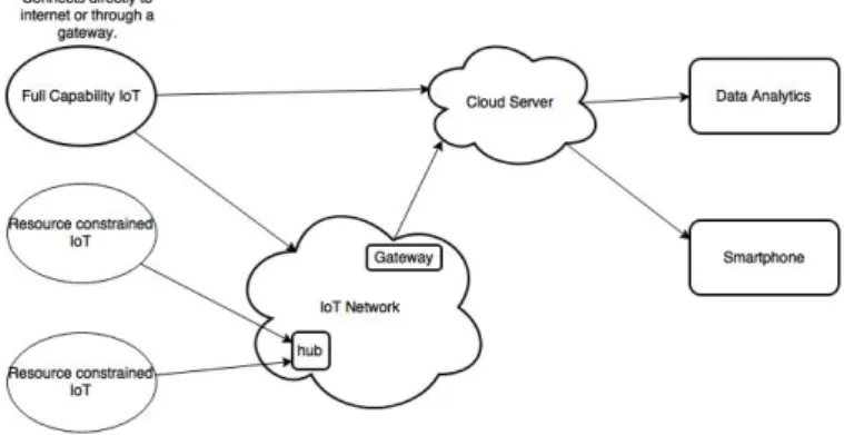
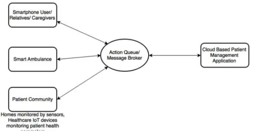
Figure 4.1 demonstrates a simplified IoT network architecture. IoT ap-plications runs as a web application on a dedicated cloud server. The server
Figure 4.1: Simplified IoT system architecture.
collects device data which is fed to data analytics module to draw conclusion suited to the requirements of enterprise deploying the architecture.
4.1.1
Deployment Scenarios with IoT
A number of different markets are integrating IoT devices into their in-frastructure and processes. IoT devices are fostering automation in fields including automotive, health–care, smart–cities, transportation and indus-tries catering to daily utilities for reducing cost and increasing energy ef-ficiency. Commercially available IoT devices such as smart meters, solar panels, etc, cater to aforesaid requirements. Moreover, IoT devices such as heart–monitoring devices, wireless insulin pumps, sensors for automobiles, smart–home appliances are also enabling development of advanced applica-tions for daily use.
4.1.1.1 Automotive
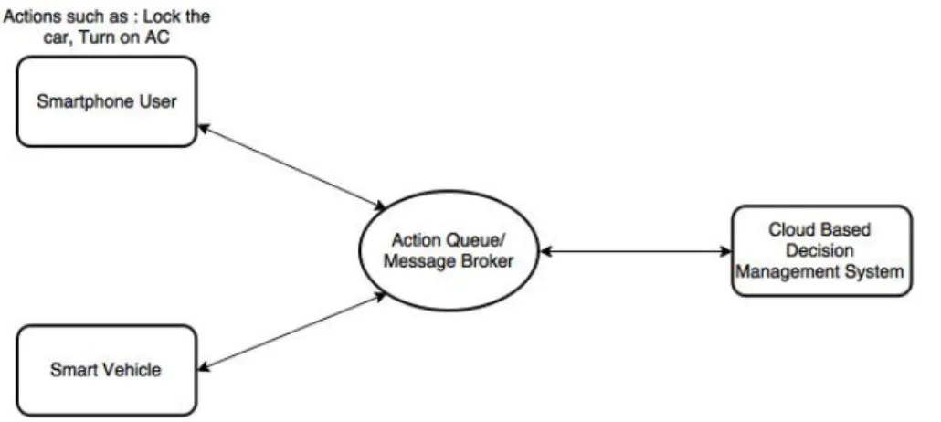
Connected vehicle technology is an ecosystem of smart–cars, trucks or buses embedded with IoT devices or internal sensors to determine accurate speed, location and temperature of the vehicle. Moreover, this ecosystem is aimed at enabling interaction between smart–vehicles with surrounding roads, build-ings, pedestrians and other smart–vehicles in order to improve road safety, reduce maintenance and insurance costs and avoid traffic congestion scenar-ios.
Figure 4.2 demonstrates the architecture for IoT applications in connected vehicular technology deployment scenario.
Figure 4.2: Automotive deployment scenario with Smart vehicular technol-ogy.
4.1.1.2 Health–care
IoT holds an immense potential to transform health–care into Internet of Health–care Things. Connected IoT devices can be used to continuously mon-itor patients with chronic conditions such as diabetes, heart–risks, etc,. to tackle emergency situations, avoid hospitalization and handle pre–hospitalization patient report generation to improve quality of life and reduce cost of care for patients with chronic diseases. Moreover, personalised IoT devices can minimize patient–doctor interaction by continuously recording, reporting and triggering emergency alarms generated over health data based on daily ac-tivities.
Figure 4.3 demonstrates the architecture for IoT applications in health– care.
4.1.1.3 Smart–cities
Smart city is a vision of interconnecting public spaces and infrastructure in urban cities through embedded sensors such as IoT devices. Smart city caters to market segments such energy, transportation, health–care, build-ings, infrastructure and governance. This concept has driven innovation and experimentation with IoT technology into adaptive traffic monitoring and controlling, self-driven cars, smart–home meters, monitoring environmental changes, resource management within a city, smart–home controllers and security systems, energy management and security solutions in office infras-tructure, improving workplace productivity, etc,. Some quick use cases where
Figure 4.3: Deployment scenario with Internet of Health–care Things.
the aforementioned technology helps include adjustment in travel schedules of commuters based on real–time tracking of public transportation, improv-ing air and water quality based on data provided through environmental monitoring, reducing electricity loss during distribution with smart–meters, etc, [78].
Figure 4.4 demonstrates the architecture for deployment of IoT applica-tions in a smart–city.
4.1.1.4 Intelligent Transportation Systems
Intelligent transportation systems are fostering the adoption of IoT devices and embedded sensors in vehicles such as cars, trucks, ships, air–crafts and passenger trains. Moreover, IoT devices are permeating into transport in-frastructure such as roadways, tunnels, bridges and railway tracks. This widespread deployment will lead to vehicle, passenger and pedestrian safety, increasing fuel efficiency, monitoring environmental pollution, routing of lo-gistics transport, efficient selection of parking space and reducing road con-gestion [28].
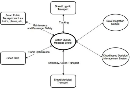
Figure 4.5 demonstrates the architecture for deployment of IoT applica-tions in intelligent transportation systems.
4.1.1.5 IoT utilities
IoT devices are increasingly becoming an important part of the utility indus-try with focus on improving energy efficiency, conserving energy and water
Figure 4.4: IoT deployment scenario in Smart–cities.
Figure 4.6: IoT deployment scenario in Smart–Home utilities.
resources, improving home safety and security, automation of daily house-work and reducing carbon emissions. This has led to adoption of devices such as smart–grids, smart–meters, smart–home appliances to enhance interaction between product, product owners and product manufacturers [29].
Figure 4.6 demonstrates the architecture for deployment of IoT applica-tions in Smart–Home utilities.
4.1.2
Impact of various IoT applications
McKinsey estimates that IoT has a potential economic impact of 3.9 trillion to 11.1 trillion dollars per year by 2025. These estimates are proposed consid-ering factors such as IoT adoption rates, economic growth and demographic trends [78].
As shown in Figure A.6, IoT applications catering to manufacturing fac-tories will have the greatest impact equalling to approximate $3.7 trillion per year. Moreover, smart–cities are the next largest IoT application deployment scenario with a potential impact of $1.7 trillion per year by 2025. Figure A.6 also demonstrates major applications that will be deployed for the specific IoT settings.
4.2
Security Attacks in IoT ecosystem
The rise of connected devices in IoT ecosystem has created a pressing de-mand for robust security mechanisms [56, 76]. The number of attacks and the tools available to potential attackers is becoming more efficient and effective as the IoT ecosystem grows [65, 100]. Moreover, Cyber threats are prevalent
against IoT deployment scenarios leading to disabling of system operation, economic loss and privacy threat to sensitive user data [33, 95]. Such secu-rity issues can hamper the deployment of IoT services and applications [48]. Moreover, hackers and attackers are showing increasing interest in exploiting the security vulnerabilities in this area [45, 107]. Hence, security and privacy are a serious concern for both device owners and manufacturers in the shift towards IoT [25, 77].
Below we list some such security attacks on various IoT deployment sce-narios :
1. In 2012, a series of hacks were perpetrated against smart–meter instal-lations in Puerto Rico costing hundreds of millions of dollars annually. The law enforcement agency expected similar threats to spread across the country as more utilities deploy smart grid technology [87].
2. In 2012, Justin W. Clarke, a security researcher from San Francisco Bay area, publicly disclosed a flaw in hardened grid and router provider RuggedCom’s switches. By accessing the private key stored in Rugged operating system, the attacker can successfully decrypt all the traffic sent to or from the switch. This can further lead to compromise of the entire energy grid [102].
3. Within a positive train control (PTC) system, the level of automation and control also exposes the system to dangerous vulnerabilities. In case, a malicious user gains system–level access, it is free to execute any set of commands to trigger unwanted automated chain of actions [18]. One such incident was reported in Poland, wherein a 14–year old hacker changed the points on the city’s tram system leading to derailment and injuring 12 passengers [35].
4. In 2014, Scott Erven and his team of security researchers released their study on the vulnerability of medical devices. The study reveals that drug infusion pumps can be remotely manipulated, X–rays can be ac-cessed by attackers on hospital’s network, attackers can take down crit-ical equipment during emergency situations and reset the configuration of testing equipment [109].
5. In the recent past, cyber attacks have been launched against public utility infrastructure such as power systems and water treatment plants to affect the distribution of water and electricity [66].
6. In early 2015, a German steel mill was attacked by hackers leading to massive physical damage. The hackers managed to manipulate and
disrupt the control systems such that the blast furnace could not shut down properly [110].
7. In 2015, two well known hackers Charlie Miller and Chris Valasek re-motely compromised Jeep Cherokee and gained complete physical con-trol over the vehicle. Prior to this, their research on vulnerabilities in connected cars lead them to hacking Toyota Prius and a Ford Escape by plugging a laptop into the vehicle’s diagnostic port allowing them to control headlights, steering and brakes [80].
8. In 2015, Samsung shipped a smart–fridge with a significant security flaw that can allow an attacker to gain access to login credential of the user. The application level implementation does not validate SSL server’s certificates [112].
9. In 2015, Marc Rogers and Kevin Mahaffey, demonstrated vulnerabil-ities found in Tesla Model S that can allow an attacker to start the vehicle by connecting a laptop to the car’s network cable. Moreover, the security researchers could also plant a remote-access trojan on the car’s internal network which allowed them to remotely control the car [111].
10. In 2015, several vulnerabilities were disclosed inHello Barbie, an iconic toy which enables children to communicate with the doll over a cloud server connection. The vulnerability allows an attacker to intercept and spoof the audio communication between the toy and children [88].
4.3
PKI as a security solution for IoT
The rise in the number of connected IoT devices has lead to increase in the challenges to secure inter–device communication. The IoT ecosystem requires proven, reliable and tested network security solutions for data confidentiality, data integrity, device authentication and device authorization. However, recent attacks on various IoT deployment scenarios as discussed in Section 4.2 demonstrate a lack of generic security architecture or standard in deployment and operation of IoT devices [73, 113].
From IoT ecosystem perspective, communications occur between the IoT devices or between IoT devices and cloud server. Data confidentiality and integrity are concerned with securing this data exchange against interception, interruption and modification. Moreover, authentication and authorization provide assurance that an IoT device is an entity it claims to be and the
IoT device is authorized to perform a particular action. As a security so-lution PKI provides and manages digital certificates which bind a public key to an IoT device identity or private key such that any other entity in the environment can validate this binding [101]. Currently, digital certifi-cates used for identity management are based on X.509 certificertifi-cates which are self–descriptive entities specified using ASN.1. X.509 certificates are en-coded using DER standards and are stored as an ASCII string using BASE64 encoding [36].
4.3.1
Security protocols in IoT protocol stack
With TCP/IP protocol stack, secure Internet communication is provided through 3 key components :
1. Network protocols such as IPsec and TLS provide authentication and data confidentiality at network and application layer for peer–to–peer communication [40, 62].
2. Digital certificates provide a valid identity to each peer in the network. 3. PKI infrastructure supports the provisioning, management and
revo-cation of the digital certificates.
This three component based security solution can further be applied to IoT networks. As shown in Figure 4.7 IoT protocol stack at network layer is based on IPv6 over Low power Wireless Personal Area Networks (6LoWPAN) [53]. Hence, network layer secure communication can be provided through IPsec. Moreover, IoT uses Datagram Transport Layer Security (DTLS) to secure application layer data. DTLS protocol is based on TLS and provides equivalent security to secure peer–to–peer communications [93]. In addition, IoT protocol stack has been optimized for low power devices and hence the data overhead generated through the stack is much smaller in comparison to the TCP/IP protocol stack [63].
4.3.2
PKI consideration for IoT
PKI is designed to provide secure communication between Internet–based client–server architecture. There are various challenges to be considered prior to adopting PKI to provide secure communication in IoT deployment scenario :
1. Peer authentication in IoT : In IP networks device authentication and secure communication for application layer data is done with TLS pro-tocol. TLS uses X.509 certificates during initial authentication phase
Figure 4.7: Comparison of IoT protocol stack with TCP/IP protocol stack.
between two peers to negotiate the session key. Moreover, only server presents a X.509 certificate to authenticate its identity with the client. It is optional for the client to present X.509 certificate during the initial authenticate phase. In case of IoT deployment scenario, it is necessary to configure TLS to provide client’s X.509 certificate for mutual authen-tication between communicating IoT devices or between IoT device and the cloud server.
2. Key Generation : IoT devices are resource constrained devices and may not have enough entropy to generate random private key. Therefore, it is preferable to generate the private key at the CA/RA server. EST certificate management protocol supports generation of client keys at CA server and further secure transportation of the key over TLS and DTLS. Moreover, the PKI solution should consider whether the key should be completely removed to maintain the integrity of generated certificates or securely store them through RA/CA server for revocation or renewal cases.
3. Choice of Cryptographic Algorithm: As shown in Figure 4.7, DTLS is the proposed protocol for securing device authentication and communi-cation for applicommuni-cation layer data. Using asymmetric encryption based on RSA and PKI certificates, imposes high energy consumption in the
IoT deployment scenario. In consequence, ECC is a better suited ap-proach for IoT deployment scenario in comparison to RSA as it is more energy efficient and offers same level of security with lesser key size [50]. Moreover, EST offers CA side support for generation of private keys based on ECC algorithm. Hence, EST can be used as the protocol for certificate management in PKI security solution for IoT deployment scenario.
4. Scalable Database Solution : PKI security solution should be effective in scaling for different IoT deployment scenarios. IoT devices can be deployed within a home or a building or over an entire city. Hence, there is a need for an efficient and scalable database management system for storing certificates that cater to different scale of IoT devices ranging from thousands to millions to billions.
5. Life–Span of Digital Certificates : The lifetime of a digital certificate may vary based on the type of IoT device, device manufacturer and IoT deployment scenario. Some situations may warrant that certificates and private keys can never be updated or replaced because they are permanently stored on the device. However, some other scenarios for IoT deployment may demand storing short–lived certificate on the IoT device. In such situation handling revocation or renewal at a high scale has to be considered in the design of the PKI solution.
6. Certificate Management Protocol : Currently, various certificate man-agement protocol such as SCEP, CMC and EST, exist for supporting secure certificate provisioning. It is necessary to consider advantages and disadvantages of each before choosing the suitable one for PKI solution.
7. Managing High–Volume Issuance : Irrespective of deployment scenario, every IoT device will be installed with a vendor certificate during man-ufacturing. This requirement necessitates a highly available, fault-tolerant and scalable CA server.
8. Number of certificates per device : Depending on the deployment sce-nario the number certificates installed on the device may vary. For example, a smart vehicle will not only need a pre–installed vendor cer-tificate but an operator cercer-tificate and other necessary cercer-tificates in order to communicate with entities such as other smart–vehicles, trans-portation infrastructure (traffic lights), etc., while on the move.
Naming of IoT Devices
To support large scale deployment of IoT devices, naming and identi-fication of the device is a pre–requisite. However, it is impossible to assign names to IoT devices from a single name–space considering the number of devices deployed will reach to billions. Naming of the IoT devices can be either hierarchical or flat. Hierarchical names cater to scalable name assignment and resolution while flat names, generated based on unique identifier such as MAC address, work as a self–certified IDs [57].
5.1
DNS name auto–configuration for IoT
devices
Currently, network devices support automatic configuration of IPv6 address using neighbour discovery [84], default gateway configuration by employing IPv6 stateless address auto–configuration [105] and DNS server configuration with IPv6 router advertisement (RA) options for DNS configuration [54]. However, DNS names have to be configured manually and will prove to be cumbersome in IoT deployment sce-nario considering the growing scale of deployed devices. For our scal-able and flexible PKI solution we will consider the auto–configuration scheme of DNS names [55]. The auto–configuration scheme generates a DNS name at the host, assisting easy monitoring and remote con-trolling of IoT devices [72]. This scheme works in unicast mode as opposed to multicast mode used in bonjour application [1] and hence, generates less network traffic. To generate the DNS name, the auto–
Figure 5.1: Message flow to demonstrate auto–generation of DNS name.
configuration mechanism needs to acquire the DNS search list (DNSSL) either through RA options [54] or via dynamic host configuration pro-tocol version 6 (DHCPv6) options [42]. DNSSL is a list of DNS suffix domain names that are used by IPv6 hosts.
The auto–generated DNS name is of the formatunique id.device model. device category.location.domain name. unique id is a unique identifier in ASCII characters. It can be a sequence of numbers or set of al-phanumeric characters. device model is the model name for the device in ASCII characters provided by manufacturer. device category is the category to which the device belongs such as refrigerator, smart–tv, smart–meter, etc,. location represents the physical location of the de-vice. domain name is the DNS domain name such as example.com or aalto.com [55].
The procedure for DNS name auto–configuration is completed in two phases. In the first phase, the IoT device generates it own DNS name and in the second phase the generated name is registered with the DNS server [72].
Figure 5.1 shows the first phase in DNS name auto–configuration. In this phase, the IoT device gets the DNSSL list through either RA or DHCPv6 options. It performs validity check on the DNSSL option received. If it is valid, then the IPv6 host or IoT device generates the unique DNS name after performing duplicate address detection (DAD). Figure 5.2 shows the second phase in DNS name auto–configuration. In this phase, an IoT device receives a node information (NI) [37] query from the router in the same sub–net. It sends the NI response with the
Figure 5.2: Message flow to demonstrate DNS name registration.
generated DNS name. The router then registers the DNS information with the DNS server through dynamic DNS update [108].
Certificate Management with
Merkle Hash Trees
Certificate management system maintained by the CA server supports insertion, deletion and searching of digital certificates. Our proposed PKI solution uses merkle hash tree data structure based on authenti-cated dictionary called as AD–MHT [81, 83] for supporting the afore-mentioned operations. Identity certificates are used to bind a pub-lic key with an identity. It is an association between a distinguished name (DN) and the requesting entity’s public key. It is necessary that each requesting entity posses a unique DN. Moreover, X.509 standard defines the data and data format for identity certificates. The data fields in X.509 certificates include version, serial number, signature algorithm identifier, issuer name, validity period, subject name and subject public–key information. Serial number is generated by the CA and is used to uniquely identify a certificate. Issuer name is the DN of the issuing entity. Subject name is the DN of the entity requesting a certificate. Moreover, validity period defines the expiration time of the certificate. The certificate has to be revoked once it is expired.
PKI handles the management of certificates during the entire lifetime. With certificate revocation an issuer can revoke the binding between the identity and the public key before the certificate expires. Certificate revocation is needed in case of loss or compromise of private keys, change of access rights of the certificate owner, policy changes at CA or as a precautionary measure against certificate forging attacks [47]. Figure 6.1 demonstrates the certificate revocation mechanism. In order to revoke a certificate the issuer initiates the revocation process and
Figure 6.1: CA reference model for certificate revocation [81].
sends a revocation request to the revocation data issuer (RDI). RDI has the access to the database of the revoked certificates and is also responsible for maintaining an appropriate status data format for the revoked certificates that can be distributed to the end–entities [81]. CMP is one of the protocol that can be used for communication in revocation reference model. Moreover, the end–entities can use CRL for status checking. CRL is digitally signed by the CA and includes information such as certificate serial number, revocation reason and revocation date [36].
6.1
Merkle Hash Tree
MHT stores data only in the leaves of the tree. The contents of the leaf nodes are hashed and combined to generate nodes for the upper level of the tree. This process is recursively applied to generate the root node of the tree which is digitally signed by the CA to authenticate the entire MHT [81].
Figure 6.2 shows a sample MHT. MHT employs properties of one way hash functions (OWHF). OWHFs are 10,000 times faster to compute than digital signatures. Ni,j denotes a node in MHT where i represents
Figure 6.2: An example of MHT [81].
the depth or the level of the node and j represents the number of the node. Moreover, Hi,j is the hash value stored by the node Ni,j. The
nodes at level 0 are called leaf nodes and they store the data in the tree. The data stored is represented by the set φ[79].
φ={c0, c1, c2...cn}
where cj is the data stored by leaf node N0,j. Hence,H0,j can be computed
as :
H0,j =h(cj)
where h is the OWHF. In order to construct a MHT, a set of t adjacent nodes at level i; Ni,j, Ni,j+1, ..., Ni,j+t−1 are concatenated to create the node for
upper level which is denoted byNi+1,k. Hence,Hi+1,kis obtained by applying
h or OWHF to the concatenation which is denoted by the equation as : Hi+1,k=h(Hi,j|Hi,j+1|...|Hi,j+t−1)
The root node at the top level is a digest for all the data stored in the MHT. MHT shown in Figure 6.2 is a binary tree with the adjacent nodes combining in pairs to form the node in the next level. MHT–AD is a 2–3 tree structure where each internal node has two or three children. For a MHT–AD with n leaves, certificate management operations such as insertion, deletion and search can be performed in O(log(n)) time. Each leaf in the MHT-AD