Internet of Things Architecture
FP7 Contract no.: 257521
WP3 - Protocol Suite
Deliverable D3.3
Deliverable ID: IOT-A_WP3_D3.3
Deliverable Title: D3.3 Initial IoT Protocol Suite definition
Deliverable Editor: Michele Rossi (CFR)
Authors: Alexandru Serbanati (CATTID), Alexis Olivereau (CEA), Alessan-dro Bassi (HEU), Andreas Nettstraeter (FhG), Angelo Castellani (CFR), Konstantinos Koutsopoulos (CSE), Pierpalo Giacomin (HEU), Michele Rossi (CFR), Riccardo Bonetto (CFR)
PROPRIETARY RIGHTS STATEMENT
This document contains information, which is proprietary to the IOT-A Consortium. Neither this document nor the information contained herein shall be used, duplicated or communicated by any means to any third party, in whole or in parts, except with prior
Document Information
Deliverable ID: IOT-A_WP3_D3.3
Deliverable Title: D3.3 Initial IoT Protocol Suite definition
Version: Draft
Version Date: April 12, 2012
Editor: Michele Rossi (CFR)
Authors: Alexandru Serbanati (CATTID), Alexis Olivereau (CEA), Alessan-dro Bassi (HEU), Andreas Nettstraeter (FhG), Angelo Castellani (CFR), Konstantinos Koutsopoulos (CSE), Pierpalo Giacomin (HEU), Michele Rossi (CFR), Riccardo Bonetto (CFR)
Contents
Contents 1
1 Introduction 5
2 Networks and communication entities 5
2.1 Network Types . . . 5
2.2 Terminal Types . . . 6
2.3 Gateway . . . 6
3 Communication types 7 4 Communication scenarios 7 4.1 Scenario S1 (Unicast and Multicast) . . . 8
4.2 Scenario S2 (Unicast) . . . 8 4.3 Scenario S3 (Unicast) . . . 8 4.4 Scenario S4 (Unicast) . . . 8 4.5 Scenario S5 (Multicast) . . . 9 4.6 Scenario S6 (Anycast) . . . 9 4.7 Required Functionalities . . . 10 5 Security Scenarios 10 5.1 Security Functions . . . 11 5.1.1 Integrity . . . 11 5.1.2 Source authentication . . . 11 5.1.3 Confidentiality . . . 11 5.1.4 Non repudiation . . . 11
5.1.5 Traffic flow confidentiality . . . 12
5.2 Security Elements . . . 12
5.2.1 Nodes capabilities and impact on security . . . 12
5.2.2 Network entry. . . 12
5.2.3 End-to-end vs. Hop-by-hop security . . . 13
5.2.4 Trust model involvement . . . 14
5.2.5 Shared secret establishment . . . 14
5.3 Security Scenarios . . . 16
5.3.1 Secured network entry, enabling hop-by-hop security. . . 16
5.3.2 Hop-by-hop security in the constrained domain only . . . 16
5.3.3 Secured communications between constrained devices . . . 17
5.3.4 Server-assisted group security for constrained devices . . . 17
6 Gateway Functionalities 18 6.1 Communication Scenario S1 . . . 19
6.1.1 External Network Access . . . 20
6.1.3 IoT Devices and Services Registry . . . 20
6.2 Communication Scenario S2 . . . 21
6.2.1 External Network Access . . . 21
6.2.2 M2M Communication Bridge . . . 21
6.2.3 IoT Devices and Services Registry . . . 21
6.3 Communication Scenario S3 . . . 22
6.3.1 External Network Access . . . 22
6.3.2 M2M Communication Bridge . . . 22
6.3.3 IoT Devices and Services Registry . . . 23
6.4 Communication Scenario S4 . . . 23
6.4.1 External Network Access . . . 23
6.4.2 M2M Communication Bridge . . . 23
6.4.3 IoT Devices and Services Registry . . . 24
6.5 Communication Scenario S5 . . . 24
6.5.1 External Network Access . . . 24
6.5.2 M2M Communication Bridge . . . 24
6.5.3 IoT Devices and Services Registry . . . 25
6.6 Communication Scenario S6 . . . 25
6.6.1 External Network Access . . . 25
6.6.2 M2M Communication Bridge . . . 25
6.6.3 IoT Devices and Services Registry . . . 25
7 IOTA Protocol Stack 26 7.1 Protocol Stack Components . . . 26
7.2 Security Procedures . . . 31
7.2.1 Network Entry Procedure . . . 31
7.2.2 Establishment of a Secure Connection . . . 34
7.3 M2M Layer . . . 37
7.3.1 UPnP . . . 37
7.3.2 DPWS . . . 42
7.3.3 IETF CoAP . . . 48
7.4 Comparison among M2M protocols. . . 53
7.4.1 Architectural Communication Model . . . 53
7.4.2 Protocol Stack Requirements . . . 54
7.4.3 Suitability for Constrained Devices . . . 54
7.4.4 Comparison in Terms of Security Features . . . 55
7.4.5 Concluding Remarks. . . 55
7.5 Protocol Translation for M2M Interoperability. . . 56
7.5.1 Security considerations . . . 59
7.6 Transport Layer . . . 60
7.6.1 Optimization for Constrained Networks . . . 60
7.6.2 Optimization for Unconstrained Networks . . . 62
7.7 ID Layer . . . 66
8 Example for the Establishment of an End-to-End Secure Channel 68 8.1 Practical Security Considerations . . . 69
8.2 An IPsec-based Security Association Example . . . 70
List of Figures
1 Communication scenario S2. . . 8
2 Communication scenario S4. . . 8
3 Communication scenario S5. . . 9
4 Communication scenario S6. . . 9
5 Network entry procedure. . . 13
6 End-to-end vs. Hop-by-hop Security . . . 14
7 General IoT-A WP3 Security Architecture. . . 27
8 EAP-based Network Entry. . . 32
9 High-level view of the Network Entry Procedure. . . 33
10 KEM-assisted shared secret establishment. . . 34
11 Collaborative key establishment wherein the initiator relies on assisting nodes to perform heavy cryptographic operations in the delivery of a secret value x to the responder. . . 34
12 High-level view of the establishment of a secure channel with a distant peer. . 36
13 UPnP standalone implementation. . . 40
14 UPnP bridge-type implementation. . . 41
15 DPWS protocol stack. . . 43
16 Schematic view of a DPWS gateway. . . 47
17 CoAP-based protocol stack. . . 51
18 Translation among different M2M standards for communication scenario S2. . 57
1
Introduction
The objective of this document is twofold: 1) detailing the communication scenarios that we foresee for Internet of Things and especially for their usage within wider Internet networks and 2) presenting the initial design for the protocol stack within WP3.
1) Communication scenarios: for the first objective we detail the technical scenarios that are relevant to the design of the IOTA protocol stack in WP3. Our emphasis here will be on communication aspects and as such we will be focusing on: 1) the type of networks, including their capabilities and 2) the type of terminals, including their ca-pabilities, which will be involved in the communication, 3) the type of communication path that is involved in the end-to-end communication between terminals, i.e., which type of networks and terminals are involved in the end-to-end communication. Note that for communication within WP3 we generally mean end-to-end communication oc-curring between a pair of terminals, which are possibly located within different network domains.
The end-to-end communication involves:
APP The communication at the application layer (mandatory) TRA Transport functionalities (optional)
ROU Routing functionalities (mandatory)
SEC End-to-end security functionalities (optional but recommended).
2) Protocol design: we present the initial reference IOTA protocol stack detailing the role of each layer. As one of the main requirements of the stack is to be compati-ble with existing applications wherever possicompati-ble, the document will discuss the avail-able techniques/mechanisms that can be used at each layer with no or little change. In latter case, we illustrate available standardization activities along with their exist-ing implementations, givexist-ing recommendations for their usage and/or their adaptation for coexistence with other standards (either residing at the same of different layers). Where standards or solutions are not available, we will provide our own, motivating our design choices and providing guidelines for the implementation of the corresponding schemes.
2
Networks and communication entities
2.1
Network Types
In this documentnetworksare classified as unconstrained (NTU) or constrained (NTC) : • NTU: Unconstrained networks are characterized by high speed communication links
(e.g., offering transfer rates in the Mbit/s range or higher) as the wired Internet of today. Link level transfer latencies are also short and mainly impacted by possible congestion events in the network rather than by the physical transmission technology.
• NTC:Constrained networks are characterized by relatively low transfer rates, typically smaller than 1 Mbit/s, as offered by, e.g., IEEE 802.15.4. These networks are also characterized by long latencies and this is due to several factors including: 1) the involved low rate physical layer technology and 2) the power saving policy of the termi-nals populating these networks, which may imply the periodic power off of their radios for energy efficiency purposes.
2.2
Terminal Types
For what concernsterminals, three categories are defined unconstrained (TT1), constrained (TT2), and tag-type (TT3):
• TT1:Unconstrained terminals have sufficient computational power and energy reserve to implement complex tasks, e.g., implementing complex security functions, dealing with standard HTTP traffic, XML and supporting the high transmission rates that are typical of NT1 networks. Internet servers, fixed and laptop computers are classified as unconstrained terminals.
• TT2: Constrained terminals have: 1) reduced transmission capabilities in terms of transmission rates (usually smaller than 1 Mbit/s), 2) constraints in terms of energy reserve as these terminals are usually battery operated or co-powered through energy scavenging circuitry, 3) constrained in terms of memory storage, typical values are RAM smaller than 10 Kbytes, ROM smaller than 100 Kbytes, 4) constrained in terms of computational capabilities, typically their micro-controllers have clock speeds smaller than 100 MHz.
• TT3: Tag-type terminals are typically not able to participate in an end-2-end IP com-munication. This is justified due to their extreme limitations in computing power, mem-ory storage and limited energy storage. Some typical Near Field Communication (NFC) tag-types are limited to a storage of 48 bytes [NFC-Forum] - RFID tags may be even limited to send an ID without being able to store information. (NFC-Forum: http://www.nfc-forum.org/specs/spec_list/#tagtypes) The typical access to those kind of tags is implemented via direct communication with a reader device, which is a con-straint or even unconcon-straint device and realizes the end-to-end IP-based communica-tion.
2.3
Gateway
Gatewayin the current document refers to the communication entity that has the role of either bridging different networks - generally of different Network Types - or relaying messages between different Terminal Types. These two interworking aspects can be combined in case it is required by the communication scenario. In this context the Gateway is supposed to:
• offer a number of physical interfaces through which different Network Types can be accessed,
• interoperate with a number of communication protocols ranging from layer 2 to layer 4, • implement and M2M logic in the context of IOT-A defined model that allows it to
inte-grate a wide range of devices.
3
Communication types
In the following, we describe the types of communications that we foresee for IoTs: • UNI:Unicast: involves the communication between two terminals.
• MUL: Multicast: a single terminal sends data to a group of terminals which may be located within the same or a different network domain.
• RMU:Reverse multicast: a group of terminals send data (possibly aggregated at some intermediate point) to a single terminal located within the same or a different network domain.
• ANY: Anycast: a single terminal (the sender) sends data to a destination terminal, which is selected based on a set of attributes specified by the sender rather than on its specific identity or network address. As an example, a monitoring server may be interested in the temperature in a given room and, as such, will issue a command to address any of the sensor located within the room (the physical location in this case will be the attribute).
• BRO: Broadcast: a single terminal (the sender) sends data to all terminals of a net-work. This can be performed either at Datalink or Network layer. In some cases it is possible to specify the distance the message should be sent to in terms of network morphology. This function is essential for nodes that need to discover services over an unknown network that doesn’t implement a Discovery component.
4
Communication scenarios
With the termsresource anduser in this document we mean the devices hosting the com-munication endpoint and, more specifically:
Resource is the device having access to sensed data and can either be constrained or uncon-strained.
User is the device requiring data from a resource and can either be constrained or un-constrained. Note: a user becomes a resource when it requires data from another resource. That is, the term is associated with the current action taken / device role. The communication scenarios are presented in the next subsections in increasing order of complexity.
4.1
Scenario S1 (Unicast and Multicast)
S1 (UNI / MUL): in this communication scenario one (multiple) user(s) communicates with a single (multiple) resource(s) and all terminals are placed within the same network, which can either be constrained or unconstrained. This scenario comprises unicast as well as multicast communication, depending on the number of users and resources involved.
4.2
Scenario S2 (Unicast)
G
NTU
NTC
U
R
Figure 1: Communication scenario S2.
S2 (UNI): a single user (U), placed within an NTU, communicates with a single resource (R) placed within an NTC. The two networks are connected through a gateway node (G). Forwarder nodes may be used within both networks to route the data: routing within the NTU may occur according to standard solution, i.e., IP routing, whereas dedicated solutions are needed for the NTC. A diagram for this scenario is shown in Fig.1.
4.3
Scenario S3 (Unicast)
S3 (UNI): a single user (U), placed within an NTC, communicates with a single resource (R) placed within an NTU. The two networks are connected through a gateway node (G).
4.4
Scenario S4 (Unicast)
G
NTU
NTC
U
R
NTC
G
S4 (UNI): a single user (U), placed within an NTC, communicates with a single resource (R) placed within a different NTC. The two networks are connected through an NTU and gateway nodes (G) are used to connect constrained and unconstrained networks. Forwarders are used within the NTU to route the data and may also be used within the two NTCs. A diagram for this scenario is shown in Fig.2.
4.5
Scenario S5 (Multicast)
G
NTU
NTC
U
R
Figure 3: Communication scenario S5.
S5 (MUL): in this scenario a single user positioned within the unconstrained network com-municates through a multicast tree to multiple resources, which are located within the con-strained network and belong to a multicast group. The corresponding diagram is shown in Fig.3. This scenario comprises both the multicast case (MUL) where the user sends com-mands to multiple resources and the reverse multicast case (RMU) where the resources send data back to the user. This scenario also includes the cases where 1) users are placed within the NTC and resources are placed within the NTU and 2) users and resources are placed within constrained networks as in scenario S4 above.
4.6
Scenario S6 (Anycast)
G NTU NTC U R SERVER 1 2 3 NTU NTC U R 2 1 G Case a: Case b:Figure 4: Communication scenario S6.
S6 (ANY): in this scenario a user placed within the NTU communicates with a resource placed within the NTC. However, the user does not specify the full address of the resource
but rather a set of attributes that the resource should satisfy and an address that identifies the NTC. This scenario can be further specialized as shown in Fig.4according to two cases:
Case a: this first case entails the use of a smart (or application level) gateway. In this case, the user (U) first connects with the gateway through its own address, specifying a set of attributes for the resource of interest. After this, in a second step the gateway, which should know the attributes of the resources within its NTC and their current status, con-tacts the most appropriate resource (R) specifying the address of the original caller (U) in the message. From here on, the user U may connect directly to selected resource R as per scenario S2.
Case b: in this second case the user (U) first connects with a server, specifying a set of at-tributes of interest for a given NTC. All the resources within the NTC are known to the server, which keeps a local copy of their attributes and statuses. Thus, the server sends back to the user a message which specifies the most suitable resource (R) within the NTC, including the corresponding network address. From here on, the user U may connect directly to the resource R as per scenario S2.
4.7
Required Functionalities
In each of the above scenarios we foresee end-to-end communication occurring among the involved terminals and this communication entails:
• Addressing: the usage of a common (or compatible) addressing scheme at the layer 3 of the networks involved. This functionality is mandatory.
• Routing: the use of suitable routing algorithms which will sit on top of the addressing scheme and may differ for the different networks involved. This functionality is manda-tory.
• Transport: a transport solution to ensure a certain level of end-to-end reliability and congestion control. The transport functionality may be split at the gateway, which will thus act as a proxy. In this case the most appropriate transport algorithm can be im-plemented inside each network. The drawback of this solution is the higher complexity required at the gateway, which must include layer 4 algorithms. The transport function-ality is mandatory.
• Security:security features that can be enforced. Wherever possible we suggest using an end-to-end communication approach. This functionality is optional for the establish-ment of a IoT communication channel but highly recommended and will thus covered by the communication stack of WP3.
5
Security Scenarios
In this section, we take the above communication scenarios (including the definition of de-vices and networks) into account in order to define suitable security scenarios for IoTs. The
objectives of this section are:
• The definition of security goals;
• The identification of suitable encryption and authentication algorithms for the different network and device classes;
• The identification of suitable security protocols (including the handshake(s) needed to bootstrap security routines) for the different network and device classes.
5.1
Security Functions
This section reviews the security functions that can be envisioned in IoT-A.
5.1.1 Integrity
Integrity service is provided when the recipient of a message can verify, through a crypto-graphic means, that a received message has not been altered “en route” since it has been sent. Cryptographic enablers are Message Authentication Codes (MACs) when symmetric cryptography is used, or digital signatures when asymmetric cryptography is used.
5.1.2 Source authentication
Source authentication is provided when the recipient of a message is given a cryptographic proof of the identity of the sender of a received message. Cryptographic enablers are MACs when symmetric cryptography is used, or digital signatures when asymmetric cryptography is used. As opposed to peer-to-peer security, group security discards the use of shared secret-based message authentication codes. Source authentication primitives in group context are based on asymmetric cryptography or advanced symmetric schemes such as TESLA (Timed Efficient Stream Loss-tolerant Authentication [1]).
5.1.3 Confidentiality
The confidentiality service prevents transmitted data from inspection by an eavesdropper. The sender applies cryptographic processing to the data it sends in order to obfuscate it to all network entities except the legitimate receiver(s). Cryptographic enablers are symmetric or asymmetric encryption/decryption algorithms.
5.1.4 Non repudiation
The non-repudiation service prevents the sender of a data unit to later pretend that it did not send this data unit. This is achieved through the use of asymmetric cryptography, wherein the sender is asked to sign the data unit with its private key.
5.1.5 Traffic flow confidentiality
Traffic flow confidentiality service prevents an attacker from inducing the status of a node simply by examining traffic patterns to/from that node. For example, determining which spe-cific action is triggered on an actuator and when. This service can be provided by introducing (encrypted) faked messages in a conversation, or by arbitrarily changing the size of the data packets exchanged between two nodes.
5.2
Security Elements
5.2.1 Nodes capabilities and impact on security
From the security point of view, the heterogeneity of M2M nodes leads to defining classes among them that specify the security primitives they can use. A high-level overview lead to a three-class split:
• Highly resource-constrained sensor nodes, unable to support public key cryptography. This correspond to the less powerful TT2 terminals and almost all TT3 terminals. • Other sensor nodes, less constrained, able to use only public operations of
asymmet-ric cryptography. In an asymmetasymmet-ric cryptosystem, public operations are cryptographic operations performed with the public key, namely plaintext encryption or signature ver-ification. These operations have been shown in [2] to be far less resource demanding than operations involving the use of a private key in RSA cryptosystems. These nodes, able to use public operations of asymmetric cryptography, correspond to the most pow-erful TT2 terminals.
• M2M nodes with high energy, computing power and storage capabilities (e.g., line-powered remote servers). This category corresponds to TT1 terminals.
5.2.2 Network entry
As the first security operation performed when a node enters (through initial bootstrap-ping or mobility) the IoT topology, a network entry procedure is likely to be required, see Fig.5. This procedure is accomplished make sure that a newly arrived node is authorized to send/receive packets over the IoT topology. Depending on the local architecture and tech-nologies, different network entry procedures can be envisioned. In most cases, a network entry procedure leverages on an authentication phase, followed by the establishment of a shared secret between the newly arrived node and the node(s) in charge of network ac-cess control enforcement. This shared secret is then used to protect (source authentication and data integrity) the traffic exchanged between the newly arrived node and the controlling node(s) (such as ad-hoc neighbor, access router, unconstrained gateway, etc.).
Figure 5: Network entry procedure.
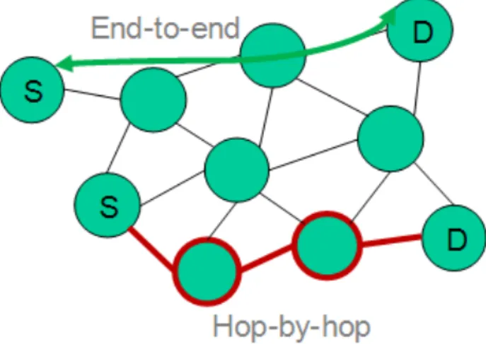
5.2.3 End-to-end vs. Hop-by-hop security
End-to-end security means that both endpoints that wish to establish a secure communi-cation share a common cryptographic secret that can be used for encryption and integrity check and ensures that no other peer can interfere with the exchanged data. For example, a data packet would be encrypted at node S with a certain secret key, and decrypted at node D using the same secret key. Therefore, end-to-end security requires that both peers S and D have initially agreed on a shared secret, used to enable cryptographic security protection between them.
On the other hand, hop-by-hop security assumes that security will be provided on multiple contiguous segments on the path from S to D. A certain cryptographic protection will be applied between S and intermediary node I1, then another between intermediary nodes I1
andI2, etc. Eventually, another is used betweenIn and D. Of course, all intermediary nodes
I1,l2, ... ,In on the path from S to D have access to the plaintext exchanged between these
nodes, including the ability of modifying the exchanged data, if integrity protection is provided on a hop-by-hop basis. Yet, this scheme can advantageously be used if, for example, both S and D already have a security context with a third party they both trust. For example, as a result of their respective network entry procedures, S and D may have established a secure context with acommon gateway. Communication from S to D may not require, then, an additional end-to-end security protection.
Figure 6: End-to-end vs. Hop-by-hop Security
5.2.4 Trust model involvement
Reliance on a trust model may be especially useful for enabling hop-by-hop security, for example if two nodes about to communicate together discover that they both trust a common third party (e.g., two constrained devices trusting a common gateway through which they can securely communicate).
5.2.5 Shared secret establishment
Whenever end-to-end security is to be used, a shared secret has to be established between the two communicating peers as a first step. This shared secret will later be used either directly as a key for a certain cryptographic primitive, or to derive further cryptographic ma-terial (e.g., distinct keys for integrity and confidentiality services). Multiple authenticated key exchange (AKE) protocols exist for this purpose. They depend on the credentials that both peers exploits for mutual authentication. As an example, the EAP [3] protocol allows the use of a wide variety of authentication methods, most of which allow the derivation of a master session key. Of course, it is important to definewhat is authenticated in the authenticated key exchange: for example, a name or an IP address.
It is also worth noting that the key exchange step is generally very expensive in terms of required computing power, whereas subsequent use of the generated key(s) is in general much more light. This is due to the fact that mutual authentication without initial knowledge and derivation of a shared secret having the perfect forward secrecy property involves the use of computationally heavy algorithms (for example, respectively RSA and Diffie-Hellman). Depending on the node capabilities and the initial knowledge they have on each other, dif-ferent key establishment systems can therefore be envisioned in IoT-A:
• Standard key exchange mechanism. A standard key exchange mechanism involves the use of a dedicated protocol, which is generally bound to the subsequent integrity/ encryption scheme. For example, the Internet Key Exchange (IKE [4]) protocol is the
standard way for automatically establishing IPsec security associations, including gen-eration of the required shared secrets. Key exchange generally requires mutual au-thentication. Yet, in some cases, it is acceptable to have "better-than-nothing" [5] se-curity.
• Standard, address-based key exchange mechanism. An address-based key ex-change mechanism ex-changes the above scheme in that the identifiers used by peers to authenticate to each other are their IP addresses, built as Cryptographically Generated Addresses (CGA [6]). The Host Identity Protocol (HIP [7]) or a CGA-enabled [8] IPsec make use of such a mechanism.
This scheme can advantageously benefit from a secure, trustworthy resolution system that is itself responsible from returning an IP address corresponding to a looked up resource. Provided that this IP address is cryptographically generated, it can imme-diately be used to leverage a key establishment phase, without requiring additional credentials such as certificates.
In addition to the change in authentication identifiers (IP addresses instead of, for ex-ample, certified identities) a key exchange system bound on cryptographically gener-ated addresses also changes the way a shared secret can be derived between both peers. For example, usual IKE-based key exchange methods are replaced in HIP with a specific one, which makes use of the available key material.
• Server-assisted key exchange mechanism. This third scheme introduces a third party in the key exchange operation. An example of this scheme is the Kerberos [9] system. In Kerberos, a client receives the shared secret it will subsequently use with a server from a Ticket Granting Server (TGS]. The TGS also delivers the same secret to the server itself. Eventually, both peers (client and server) can exchange secure data without having been involved in a peer-to-peer key agreement protocol. The example of a more global framework can be found in [10], which defines various family of solutions in which a client and a server obtain a means to bootstrap secure communications from a remote (AAA) server.
This key exchange scheme is interesting in that most of the key exchange burden is centralized at a third party server and does not drain energy from IoT devices. A key kAB is simply generated at the server and is -securely- communicated to both A and B.
This scheme can also be used in a PKI-less infrastructure where two devices have to establish a shared secret without being able to authenticate each other. If a device A can be authenticated by its AAA serverAAAAonly and a device B can be authenticated
by its AAA serverAAAB only, then A and B have to rely on each other’s AAA server to
generate a common shared secret between them. This represents a realistic, yet more complex, form of server-assisted key exchange.
• Collaborative key exchange mechanism. Collaboration can be leveraged for estab-lishing a shared secret between two entities that have not enough knowledge of each other, or not enough resources to do it otherwise. Hop-by-hop security could be used, for example, to trigger establishment of a shared secret between the two endpoints of
a hop-by-hop connection. Of course, the derived security connection will be far from perfect in that each intermediary node will eventually be able to obtain the end-to-end secret. Yet this latter might be used for authentication purpose only of an authenti-cated Diffie-Hellman exchange, which would protect the final secret against all passive attacks.
Alternatively, collaboration can be used on a larger scale basis, wherein multiple nodes, not necessarily on the path between the two parties, collaborate in order to enable the establishment of a shared secret between them. This will prove particularly useful when one node is too resource constrained to take part to the (costly) key agreement exchanges. Delegating heavy cryptographic computations to more powerful trusted nodes would be the only solution for nonetheless agreeing on a secret key with a more powerful remote peer.
5.3
Security Scenarios
5.3.1 Secured network entry, enabling hop-by-hop security
This scenario assumes that a network topology is formed of multiple nodes that have all undertaken a secured network entry procedure before being considered as valid members. As a consequence and as part of the network access control procedure, each terminal is then to send/receive data through the gateway, over a secure tunnel. Security services afforded to the sent/received data packets would normally only include integrity and source authentication. This is what is needed by the terminal and gateway to certify that they are still communicating with the initially authenticated peer.
When two (constrained) terminals want to communicate together in a secure manner, they can do it on a hop-by-hop basis through the gateway, provided that they do not need the confidentiality service. Confidentiality would require that both peers update their secure channel to the gateway, so as to also enable hop-by-hop confidentiality.
This security scenario is relevant to communication scenario S1.
5.3.2 Hop-by-hop security in the constrained domain only
In this security scenario, a constrained device is exchanging data with an unconstrained device (as per communication scenarios S2 and S3). Depending on the type of architecture in the constrained domain, different approaches can be envisioned:
• Simplex hop-by-hop security through the gateway. In this scheme, data is secured on a hop-by-hop basis, using a certain security mechanism on the path between the constrained device and the gateway, and another security mechanism on the path between the gateway and the unconstrained device.
• Collaborative end-to-end security establishment [11]. This scheme fits better to non-hierarchical model wherein an entity playing the role of the gateway does not emerge clearly. Typically, the node connecting the constrained domain to the rest of the world may be more powerful than the other nodes in the constrained domain
while being yet too constrained to terminate all security tunnels in both directions. Or the use of this scheme may also be mandated by a strong requirement of confiden-tiality, because of which constrained nodes would not want to expose their data to any intermediary node. Various hop-by-hop transports of key elements from a highly con-strained node to less concon-strained nodes would then take place, each less concon-strained node playing the role of the gateway. End-to-end confidentiality could therefore be achieved provided that the number of misbehaving assisting node does not exceed a certain threshold, fixed by the secret splitting and transmitting scheme.
5.3.3 Secured communications between constrained devices
This security scenario consider how constrained devices can securely communicate across an unconstrained domain, each constrained device being locate within a constrained domain connected to the unconstrained domain through a dedicated gateway, as per communication scenario S4.
A three-segment hop-by-hop security scheme is the most realistic basis for a security sce-nario; it would consist of:
• a secure connection between constrained device 1 and its serving gateway GW1; • a secure connection between gateway GW1 and gateway GW2 (serving gateway of
constrained device 2);
• a secure connection between gateway GW2 and constrained device 2.
Note that the secured connections between a constrained device and its serving gateway could be based on the network access control mechanism used during the network entry phase. The communication between the two gateways must itself be secured. Eventually, a coherent hop-by-hop security scheme must be ensured wherein the same security services (e.g. authentication only or authentication and confidentiality) are provided, optimally with a similar security level (algorithms robustness). What is also important is that both peers taking part of the end-to-end connection be informed of all security services applied on each different hop, which is non-trivial and has to be addressed through dedicated protocolar and cryptographic operations.
An end-to-end security scheme is more difficult to establish, yet it could be envisioned it this situation too. Here also, the most complex operation is the establishment of a shared secret between both parties. Some solutions, wherein a AAA architecture is leveraged to establish a shared secret between an IoT node and an applicative server, could be leveraged and extended to enable mutual authentication and shared secret agreement between two IoT nodes. This requires, however, an existing AAA architecture (or equivalent) interconnecting the domains of the two involved IoT nodes.
5.3.4 Server-assisted group security for constrained devices
This security scenario is relevant to communication scenario S5 in that in considers bidirec-tional communications between a server and a group of constrained devices. The security
of this scenario is said to be server-assisted in that the secure group management is en-sured by a dedicated entity acting as a Group Controller and Key Server (GCKS). As a first part of this scenario, the secure multicast group has to be built by the GCKS, which should therefore deliver to all group members the security material needed to be able 1) to decipher messages sent to the group (MUL) and 2) to generate reverse multicast (RMU) messages identified as originated in the group.
The simplest and recommended option consists for each gateway to provide a certain shared secret to all served constrained nodes belonging to a given group. If the group is limited to members of a single constrained domain, the serving gateway of that domain will then act as a GCKS for the group. Otherwise, the serving gateway of each constrained domain acts as a sub-GCKS, delivering group cryptographic material to the constrained devices it is in charge of.
If an end-to-end security scheme is applied, the other endpoint of the secure connection, namely the unconstrained device communicating with the group, must be provided with the same cryptographic material, in order to send encrypted data to the group or to authenticate messages received from the group member. This cryptographic material would be learned through a dedicated exchange with the GCKS. How the unconstrained device would learn the location of the GCKS should normally be a WP4 issue. Hop-by-hop security could be applied also, and could be a straightforward approach if the trust model allows it, as the gateway (responsible of last hop encryption with group shared secret) would also be on path of the multicast traffic (last multicast router on the path from the source to the group members).
6
Gateway Functionalities
It is clear from the communication scenarios that the IoT comprises various types of end-points and networks. IoT gateways will play a key role in establishing communication be-tween the endpoints, as well as providing the endpoints with access to networks which they do not have the means to access by default. In particular, the gateways will have the fun-damental role of providing PHY and MAC layer bridging between networks. In addition to this, there are further functionalities that are needed for the correct interworking of devices across constrained and unconstrained networks. These functionalities span from security functions to protocol translation and in some cases consist of running dedicated protocols (e.g., addressing) for the constrained domain.
Minimum functionality set: the minimum set of functionalities that the gateway should pro-vide consist of MAC layer bridging, i.e., the gateway in this case will have the unique role of enabling communications between different PHY (and thus MAC) layer technologies. This, however, assumes that the devices within the constrained network have a full-fledged proto-col stack above the MAC layer, which is also perfectly interoperable with the protoproto-cols within the unconstrained network. While this may be the case for particular networks, it is expected to be an exception rather than the rule.
Protocol translation: more likely, the constrained terminals will adopt addressing schemes that are compatible with those in use within the unconstrained network with the difference that, for efficiency purposes, their headers and in general protocol fields that are carried in the transmitted packets will be compressed. This increases the transmission efficiency within the constrained domain, which is beneficial in terms of energy consumption. In this case, the gateway node will have to act as a so called “translation proxy”, which has to per-form runtime protocol translation of the messages passing across it. This translation will occur at the network layer (e.g., IP address translation) but also transport (e.g., TCP) and M2M (i.e., application layer) may need some sort of proxy functionality in the gateway. More details about the protocol translation functionality of the Gateway are given in Section7.5.
Gateway vs External Servers: the extra functionalities such as protocol translation may be directly implemented on the gateway or moved onto external servers residing within the unconstrained network. Note that having these functionalities in the gateway will usually provide better performance as the functionalities will be closer to the point where they are actually needed.
In the following, we analyze the required gateway functionalities for each of the aforemen-tioned communication scenarios by bearing in mind that these functionalities can also be placed onto an external server as per our discussion above
The analysis develops around three basic lines:
1. how the gateway enables the end points to access external networks, 2. the way the gateway enables M2M communication between the endpoints,
3. how the gateway can enable the end points to discover each other’s presence, as well as the services each end point can offer.
This side-by-side comparison based on the aforementioned features enables a clear distinc-tion between the funcdistinc-tionalities required by the gateway in each scenario, thus making the identification of the intricacies of each scenario straightforward.
6.1
Communication Scenario S1
In scenario S1, where all IoT endpoints are located in the same network, the gateway may perform the following tasks:
• provide physical connectivity between endpoints,
• enable the discovery of endpoints and the services each endpoint offers, so that they are available to all other endpoints within the network.
Note that in the case where the constrained network is self-organized (e.g., multi-hop wire-less sensor networks), the devices therein will not require any gateway. In this case, devices will be able to perform service/terminal discovery as well as message routing across end-points. A gateway will facilitate these operations and will be needed especially for terminals of type TT3 or very constrained terminals of type TT2.
6.1.1 External Network Access
This type of functionality is not applicable to scenario S1, due to the fact that resources between which communication takes place, are located in the same network, whether that is constrained, or unconstrained.
6.1.2 M2M Communication Bridge
A significant aspect of the gateway functionality in S1, is to provide the physical connectivity between resources present on the network. For example, if the network is based on the IEEE 802.3 protocol, the gateway will be the Ethernet switch through which traffic will be directed to the appropriate node. Similarly, if the network uses the IEEE 802.15 protocol, the gateway will be the access point through which the endpoints will be able to communicate. To take the reasoning a step further, there may be both constrained and unconstrained net-works under the control of the gateway, e.g., nodes running IEEE 802.3 and nodes running Zigbee. In this case, the gateway may possibly behave as a M2M communication bridge, providing translation services between the different protocols. In order to do so, it will also have to integrate the physical interfaces and protocol stacks necessary. In this last case, the gateway will be termed as “application gateway” to underline the fact that it provided services covering all layers of the protocol stack up to and including the application.
As a side remark, note that some of the gateway functionalities, such as the translation of M2M (application level) messages across different networks can also be performed by proxies residing within the unconstrained network.
6.1.3 IoT Devices and Services Registry
For IoT endpoints to be aware of the existence of other endpoints under the control of the same gateway, as well as to be able to use the services these endpoint are able to offer, it is necessary to maintain a central point acting as a devices and services registry. Such an entity will maintain a list of all the available resources and the services each resource can provide. Taking as a real-life example the deployment of UPnP for device discovery and control, the IoT devices and services registry is the counterpart of the UPnP control point. The IoT gateway is a good candidate to implement this functionality.
However, this is not necessary; such a registry can be implemented in a stand-alone entity present in the domain that the gateway controls or be implemented as a service residing in the unconstrained network.
6.2
Communication Scenario S2
Scenario S2 covers the case where a user within an unconstrained network, communicates with a resource in a constrained network. The two networks are connected through a gate-way node. In S2, the recommended gategate-way functionalities are summarized next:
• identifying the resource to which traffic received from the user must be routed to, • bridging the constrained network to the unconstrained network to establish
communi-cation between the user and the resource,
• publishing the services of the resource to the unconstrained network.
6.2.1 External Network Access
In cases where the constrained resource is not able to directly access the unconstrained network, the gateway will be the intermediary, implementing the hardware interfaces and protocol stacks necessary to establish physical connectivity between the user and the re-source.
6.2.2 M2M Communication Bridge
M2M communication between the user and the resource may require additional functionality on the resource. In case the end point is constrained, such functionality may not be avail-able. Therefore, it should be implemented on a separate entity, which will act as a M2M proxy, performing M2M communication operations on behalf of the device. Taking UPnP as an example, the M2M proxy would implement the UPnP protocol and thus would perform the UPnP message exchanges.
This M2M translation service may be implemented in the gateway itself or in a server resid-ing in the unconstrained network (in that case this server will be referred to as “translation proxy”).
6.2.3 IoT Devices and Services Registry
The actual resources present in the constrained network, along with the services they can offer must be exposed to the external networks, so that the user(s) present in unconstrained networks may utilize them. The devices and service registry is responsible for maintaining a list of available resources and services in the domain it is responsible for, as well as for locating the actual resource that offers a particular service.
The service registry can be implemented in the gateway or in a server residing in the uncon-strained network.
6.3
Communication Scenario S3
In scenario S3, a single user placed within a constrained network, communicates with a single resource placed within an unconstrained network using a gateway. The particular scenario imposes requirements on the gateway which are analogous to scenario S2, as the gateway is the intermediate node between the unconstrained and constrained networks. Therefore, its functionalities include:
• identifying the destination of the request and direct the request to the appropriate re-source. This functionality is optional; it is not needed when the constrained resources use IP addressing and are thus reachable directly from the external unconstrained network. In case some type of compressed-IP is used within the constrained network domain, the gateway just needs to perform protocol translation.
• PHY layer bridging: bridging the constrained network to the unconstrained network to establish communication between the user and the resource,
• making the services of the resource available to the constrained network and ensuring that the user can utilize them.
6.3.1 External Network Access
Different protocol stacks will be used by the user in the constrained and the resource in the unconstrained network. Thus, the gateway needs to implement the logic necessary to provide the translation between the protocol stacks; additionally it will have to integrate the hardware interfaces necessary for establishing the communication link between the user and the resource.
6.3.2 M2M Communication Bridge
In order for the user to discover and exploit the services offered by the resource, it must implement the related mechanism. Therefore, a twofold issue is raised.
On the one hand, if the M2M communication mechanism is based on protocols and/or func-tionalities that can not be realized on the resource, these funcfunc-tionalities must be moved towards the gateway, having the gateway act as a proxy on behalf of the constrained re-source, relaying M2M-related messages and responses between the user and the resource. The communication between the gateway and the resource in this case will be adapted to the technology that the resource supports, possibly relaying on dedicated communication and messaging protocols.
On the other hand, in case multiple resources offer the same service the gateway must be able to make a selection on the actual resource to be used.
6.3.3 IoT Devices and Services Registry
The user must be aware of the IoT resources available on the constrained network, along with the services they provide. Therefore, both resource and service availability must be ad-vertised in the unconstrained network in order to have a centralized point where this informa-tion can be stored and interrogated by users interested in using the services of a particular resource. As mentioned earlier, this centralized point may be located on the gateway, along with the service-to-resource mapping functionality. However, this is not a requirement and the IoT devices and services registry can also be located in a server.
6.4
Communication Scenario S4
According to communication scenario S4, both the user and the resource reside in con-strained networks, which are connected via an unconcon-strained network. The concon-strained networks are connected to the unconstrained networks via gateway nodes. In this scenario, the gateways must:
• PHY layer bridging: interface the constrained networks to the unconstrained network, • in case constrained resources do not support some end-to-end addressing format
(that is also understood by the unconstrained network), the gateway should identify the destination resource of the user request, and the destination user of the resource response, performing the corresponding forwarding actions. In this case, the gateway will perform the addressing functionality for the constrained resources by intercepting the messages coming from the unconstrained network and performing the adequate selection of resource within the constrained domain.
• enable the user to identify, locate and use the services of the resource. As said above, this functionality may as well reside in an external server.
• expose the services of the resource to the unconstrained network so that they can be discovered by potential users. This service can be also moved in a separate server residing in the unconstrained network.
6.4.1 External Network Access
Both gateways must provide the interfaces necessary for the resource and the user to access the unconstrained network. This includes both the hardware interfaces, as well as potential protocol bridging functionality as per scenarios S2, S3.
6.4.2 M2M Communication Bridge
Similarly to scenarios S2, S3, the gateway must implement the proxy logic to handle M2M communication between the user and the resource, for the case where the M2M commu-nication mechanism deployed requires the usage of protocols/functionality that can not be
implemented in the resource and/or the user. Depending on the limitations of the user and the resource, the proxy logic may need to be implemented on the resource gateway, only on the user gateway on both gateways or on servers residing in the unconstrained network.
6.4.3 IoT Devices and Services Registry
Due to the fact that in scenario S4 the resource is the IoT endpoint hosting services, an entity responsible for managing IoT devices and services catalogue must reside in the con-strained network. Thus, users residing in external networks, whether these are concon-strained or unconstrained will be able to locate and use these services.
6.5
Communication Scenario S5
In case the same multicast protocols are used within the constrained and unconstrained net-works, the gateway only has to perform protocol translation.
However, when dedicated multicast solutions (construction and maintenance of the multicast trees as well as addressing) are used within the constrained domain, the gateway will have to perform the following tasks:
• Identifies the requests directed to a multicast resource;
• Delivers the request to the set of nodes forming the multicast group; • Collects the responses and handles the related timeout;
• Aggregates the responses and deliver them to the user.
6.5.1 External Network Access
In the context of multicast exchanges, where the gateway locally maps a multicast request received on a unicast channel (e.g., HTTP) to a multicast channel (e.g., CoAP multicast), the nodes do not get external network access directly, but they rely on the gateway collection and aggregation process in order to deliver the responses to the user on the NTU.
6.5.2 M2M Communication Bridge
In order to enable multicast communication from the user to a set of resources, the gateway has to perform the task to identify a multicast resource. The complexity related to this task depends upon the specific multicast communication technology in use.
When assuming to have support for IPv6 multicast communication in the constrained net-work, this task could be trivial because the multicast group information is embedded in the IPv6 destination address of the resource, available in the URI. However, under a wide range
of deployments the multicast address cannot be used directly to address the multicast re-source; in this cases the URI of the multicast resource should contain a FQDN as URI au-thority, which should resolve in the external network as a unicast address, possibly directly pointing to the gateway.
6.5.3 IoT Devices and Services Registry
Multicast resources should be contained in the services registry as regular resources, marked as special resources involving communication to a group of nodes.
6.6
Communication Scenario S6
In scenario S6a, the gateway performs the following tasks: • Identifies the requests directed to an anycast resource;
• Maps the request to a suitable resource to provide the anycast resource service; • Relays the request through the constrained network;
• Provides the response to the user, when available.
In scenario S6b, the gateway does not perform any special task with respect to scenario S2 for unicast resources, or to scenario S5 for multicast resources but an external server will instead perform the required resource location/mapping service. Scenario S6b will not be further discussed in this section.
6.6.1 External Network Access
The gateway provides external network access to the nodes, as per the scenario S2 or S5, depending upon the kind of resource providing the requested service.
6.6.2 M2M Communication Bridge
In scenario S6a, the gateway has to perform the mapping between the requested anycast resource and the actual resource offering the requested service. This typically involves mapping the URI of the anycast resource to the URI of the actual resource. To perform this mapping, cooperation with the IoT services registry is required.
6.6.3 IoT Devices and Services Registry
The IoT services registry provides the means to identify which resource provides the re-quested anycast service, to this end it should contain semantical descriptions of the cur-rently available resources. A possible approach to maintain such information could be that of tagging actual resources with the URI aliases of possible anycast resources that can be offered through this resource.
7
IOTA Protocol Stack
This section presents our initial design of the IoT protocol stack. Our approach is to illustrate in the next Section 7.1the WP3 Protocol Stack Architecture by starting from its discussion from the point of view of information security. We subsequently delve into the description of its relevant communication elements as follows:
• We start with the Section 7.3 where we discuss current M2M communication tech-nologies, especially discussing their limits and the lack of interoperability among different M2M standards.
• We continue with Section7.5 where we detail our proposal to fill this gap, through the provision of aprotocol translationengine at the Gateway.
• In Section 7.6 we discuss issues related with the design of the transport protocol, detailing the innovations that will be brought by WP3.
• In Section7.7we discuss pros and cons associated with the adoption of an ID-locator split approach.
We adopted this approach as our aim is to come up with an architecture that is “secure by design”. Toward this end, we think is appropriate to start with the description of security functionalities, looking first at their interactions and needs in terms of communications (e.g., in terms of involved messages and devices) and only after that tackling the design of the actual communication elements.
7.1
Protocol Stack Components
The generic IoT-A WP3 security architecture is depicted in Fig. 7. In the right-hand side of this figure we find the IoT-A communication protocol stack. This stack is composed of the following protocols (from top to bottom):
• M2M: this is the Machine-to-Machine layer which for IoT devices is the Application layer. Work on this layer is very important for Internet of Things as it contains the ma-chinery in charge of making different network elements able to communicate with each other (i.e., the lack of interoperability of current M2M technology). Toward this end, we have to deal with message translation, when different application-layer “languages” are adopted by communicating peers. This will be covered by our design and in particular by a suitable translation proxy (which may reside in the Gateway). M2M standards are analyzed in Section7.3and in Section 7.5we detail our design to address the lack of interoperability of current M2M technology.
• TRA:this is the transport layer which is used to provide some end-to-end performance guarantees between communicating peers, especially in terms of in-order-delivery and
Figure 7: General IoT-A WP3 Security Architecture.
reliability. For IoT devices the use of a transport layer is optional and depends on the required Quality of Service (QoS). Within WP3 we propose some modifications in the following two directions: 1) how transport protocols operate within the constrained communication network: our intention here is to improve the performance over current transport approaches and 2) how data flows at this layer are routed over unconstrained networks: our intention here is to optimize (higher speeds, less overhead involved) the transmission of transport flows over unconstrained domains.
• ID:this is the identification layer. This layer is an addition to standard protocol stacks. IP addresses, since the advent of IP as the global addressing technology in the In-ternet, have been used as both “locators” (where a given entity can be found) and “identifiers” (the name of the resource, which somewhat includes its properties). Re-cently, there has been an increasing interest in the IoT community in splitting these two roles, by using IP addresses as locators and adding a further protocol layer, referred to as ID layer, to deal with the resource identification task. This has pros and cons, as we discuss in deeper detail in the following. Our approach in the WP3 protocol stack
design has been to include an ID layer by however do not requiring its adoption as mandatory. In case we have it, we will adopt the ID/locator approach, in case we do not, our protocol stack will work with current IP technology. The technology behind this layer is discussed in Section7.7.
• Network: this layer is responsible for node addressing and packet routing and is the place where the Internet Protocol resides. In WP3 we assume IP to be the technology for addressing (and in particular we focus on IPv6 due to its larger address space). Our aim is to use current IP technology outside the constrained IoT network, by exploiting the communication “language” that unconstrained terminals talk nowadays (e.g., HTTP, IP, etc.) by however introducing some adaptations within the constrained domain: this entails security as well as communication features, as it will become clearer from the next sections.
• MAC:this layer is responsible for the channel access, i.e., how devices schedules their transmissions over the physical layer transmission medium. As in the previous point, proposals for this layer are outside the scope of our design in WP3.
• Physical layer (PHY):labelledϕin the figure, the PHY deals with mo/de-modulation, PHY layer coding and actual signal transmission over the medium (radio, wires, fiber, etc.). This layer is technology specific. Our aim in IoT-A and in WP3 as well is to make systems interoperable by filling the gaps that prevent different physical layer technologies to communicate with one another. The entails the design of protocol elements at higher layers and, in turn, working on PHY layer aspects is outside the scope of our design in WP3.
The left-hand side of Fig.7includes the Functional Security Blocks of our protocol architec-ture. As is evident from this figure, these blocks are not independent of the communication stack but are tightly interrelated with it. These blocks are presented in detail in the following: • Bootstrapping and authenticationis the functional block in charge of controlling the node’s network entry. Bootstrapping does not directly fit into the scope of IoT-A, and should therefore not be a major research area. It is suggested that it be only consid-ered as a specific form of authentication. Authentication, on the other hand, is highly relevant to IoT-A and is likely to be the first operation carried out by a node when it joins a new network, for example after mobility. Authentication is performed with a remote server using an end-to-end authentication protocol such as EAP. This end to end protocol may need to be carried by a dedicated authentication transport protocol such as PANA. Upon successful authentication, a security association protocol (such as IKE followed by IPsec) is launched between the newly authenticated node and an entity in the joined network that is in charge of network access control enforcement; the authentication module is also in charge of triggering this security association protocol. The authentication module may have interactions with WP4-defined authentication and authorization modules, in order to enable leverages between them ("single sign-on" between service authentication and authentication for network access). The authenti-cation module may have interactions with key management (e.g., a node acquires key
material upon network entry) through the Identity and Key Management module. For simplicity reason, this interaction is supposed to happen through the adaptation and awareness module.
• The static profile represents the knowledge by a device of its own resources (e.g., battery, computing power, memory size, etc.), the profile it adopts (TT1, TT2, TT3) and the security settings it will use. The static profile can be read-only (preset by vendor), write-once (set by OEM) or rewritable (settable by the user).
• Collaborative action managementis invoked whenever it is determined that a node cannot fulfill by itself a task it has to accomplish, e.g., the task is too computationally heavy for the resource constrained IoT node. Thus, we may account for the support of collaborative cryptographic operations, which are characterized by the involvement of more powerful peers to offer to a highly resource-constrained node the support of advanced cryptography operations. This module interacts with a trusted entity in the constrained topology ("Local trust manager"), from which it can learn possible assist-ing peers. To elaborate, think of a resource-constrained node that has to establish a shared secret with a remote peer authenticated through a certificate, the resource-constrained node may have to rely on assisting nodes to perform ciphering of the shared secret with the recipient’s public key, whereas it would have been unable to do so by itself [11]. In this case, the collaborative actions management module would run the collaborative key exchange protocol.
• Identity and key management: this functional block is responsible for ensuring secure interactions with other nodes. It establishes node privacy by choosing which identity to use in the communication stack (hence the interaction with WP4 PN). It leverages secure communications by agreeing on a key with a peer, e.g., through a dedicated authenticated key exchange (AKE) protocol, which may be bound to the identities in use as with HIP. Alternatively, this module may interact with WP4 key management module in order to bootstrap a shared secret with a remote peer (e.g., WP4 KEM may proactively deliver a shared secret to both peers upon resolution attempt). Interac-tion with WP4 KEM may also initiate an interoperability system (e.g., for an HIP node communicating with non-HIP one), which could result in the dynamic provisioning of authenticating material, to be provided to the remote peer.
• Adaptation and awareness: this functional block is responsible for configuring the protocol stack of the node and gathering information on its current status. Regarding the interaction with the IP layer, for example, the adaptation and awareness module would push security parameters (keys) to IPsec. It would also push IP addresses (or at least, suffixes) to use, as learned from WP4 PN through the identity and key management module. As per the awareness part, this module should have knowledge on the current node’s status and on its capabilities (protocols, secrets with peers, etc.). • Group security: this functional block is responsible for enforcing multicast security at
• Security level imprintingrefers to the concept of adding on each packet an informa-tion about the security robustness that protected it on its path. This module could learn the information it adds to the packets through the awareness module. The Security level imprinting uses information available from the Adaptation and Awareness module and imprints it at a chosen layer of the protocol stack. If this occurs within the Ser-vice / M2M layer, ad hoc fields could be used in structured messages according to the specific protocols. This information could also be sent as an optional part of a header (even in lower layer protocols). Having this information at a higher layer grants that any end-to-end security features in place will also protect this content. The information contained in the imprint will include: 1) if the gateway requests authentication, 2) if the gateway is authenticated, 3) if traffic in peripheral network is encrypted (and at which layer).
• Routing security moduleimplements a protocol solution aimed at preventing/mitigating classical routing attacks. This module is likely to have relationships with Authentication & BS (because a node generally routes a packet if it comes from a trusted neighbor YET a neighbor becomes trusted when the node shares a key with it YET the key to the (at least one) neighbor may be established upon network entry). And likely it will also have relationships with a Local Trust Manager (a node will not route through a neighbor that drops all of its packets, so it needs to know whom to trust). For sim-plicity reason, these interactions are supposed to happen through the adaptation and awareness module. Routing security can be instantiated through the implementation-dependant parameters of the RPL (IPv6 Routing Protocol for Low power and Lossy Networks [12]) protocol. These parameters include the setup of the RPL security policy database (which defines which security parameters are to be applied for RPL control messages issued to a given peer) or choice of candidate neighbors through which to route (for which a trust evaluation should be performed).
• Authorization Management: this functional block manages inbound and outbound access to Services, interacting with the Authorization infrastructure component in order to: 1) Retrieve certificates for accessing other resources and 2) verify if authenticated users are authorized to access its resources (if they do not use certificates).
Table 1 below shows the security blocks that can be exploited or implemented by network elements of different type. Tags are the most resource constrained devices and may access to a very limited set of functionalities. Devices of type TT2 can be of two different classes, that are indicated here with - and + according to their resources. The former indicates TT2 devices that are only able to ask for support, whereas the latter for TT2 devices that can also provide some support in authentication and encryption procedures. A TT1 is in principle capable of taking the full burden associated with security procedures: which functionalities will be implemented of course depends on the specific implementation requirements. Note also that TT1 functionalities can be implemented in the Gateway or as well into a proxy server.
Modules TT3 (tag) TT2 (-) TT2 (+) TT1 (Gateway) Bootstrapping and authenti-cation X X X Static profile X X X X Collaborative actions man-agement X (may request support if ac-tive tag) X (may request support) X (may offer support) X
(may offer sup-port) Identity and key manage-ment X (interoperability support) Adaptation and aware-ness X X Group secu-rity X Security level imprinting X (optional) X (optional) Routing security X X X Local Trust Manager X Authorization Management X X
Table 1: Security functionalities exploited/provided by network elements of different type.
7.2
Security Procedures
In this section we discuss two relevant security procedures, namely, the Network Entry (Sec-tion7.2.1), which is used for the authentication of a IoT node to a remote server or host and the Establishment of a Secure Connection to a Distant Peer (Section7.2.2), through which a IoT node establishes a secure channel with a network element residing outside the con-strained domain.
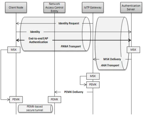
7.2.1 Network Entry Procedure
TheNetwork Entry Proceduredictates how a constrained IoT node authenticates to a re-mote server through a neighbor (possibly being the network access control enforcement point) and the gateway connecting the constrained domain to the unconstrained domain. In the depicted procedure, EAP-based authentication [13] is used between the client node and a (possibly WP4-operated) remote EAP and AAA server. EAP is carried by the PANA protocol [14] between the client node and the gateway, and by a AAA protocol (such as [15])