HVA200
High Voltage Amplifier
18014-D02 Rev B, Jan 26, 2009 Page 2 www.thorlabs.com
Table of Contents
Part 1.
Important Safety Notice ... 3
Part 2.
Product Overview ... 4
Part 3.
Setup and Operation... 5
3.1. HVA200 Controls and Features... 7
Part 4.
HVA200 Specifications ... 8
Part 5.
Maintenance ... 10
5.1. Fuse Replacement ... 10
5.2. Ventilation ... 10
5.3. Troubleshooting ... 10
Part 6.
Warranty Information... 11
Part 7.
Declaration of Conformity ... 12
Part 8.
Regulatory ... 13
Part 9.
Thorlabs Worldwide Contacts ... 14
Table of Figures
Figure 1: HVA200 Front Panel Features... 7Figure 2: HVA200 Rear Panel Features... 7
Part 1. Important Safety Notice
Danger High Voltage
The HVA200 can produce hazardous voltages and
currents which may be harmful or even lethal. Use
caution and exercise preventative safety measures
to prevent contact between these high voltages and
any personnel.
Warning!
The line switch and fuse must be set to the correct
mains voltage. The unit is shipped ready to
operate on 115 V. To operate on 230 V, the line
switch and fuse must be changed. See Section 5.1:
Fuse Replacement.
Do Not Open Housing!
The HVA200 has no user-serviceable parts. Service should only be
performed by trained service personnel.
18014-D02 Rev B, Jan 26, 2009 Page 4 www.thorlabs.com
Part 2. Product Overview
The Thorlabs HVA200 High Voltage Amplifier is designed to directly drive the Thorlabs Electro-Optic Modulators. The amplifier features: a large, ±200 V output, a continuous current output of 100 mA, a wide, 1 MHz bandwidth, and low noise. The voltage gain of -20 boosts the input up to the high voltages needed to drive our lithium niobate broadband modulators. An adjustable bias allows for precise DC offset control.
The HVA200 uses a high voltage, wideband, high slew rate output amplifier to achieve an output range of ±200 V at a bandwidth up to 1 MHz. The input amplifier includes a summing junction which allows an adjustable DC bias to be added to the input modulation. This composite signal is then boosted by a fixed voltage gain of 20 by the output amplifier. For added safety, a front panel HV Enable button must be pressed to connect the HV output to the output BNC. The output is automatically disabled each time the HVA200 is powered on.
The DC Bias control consists of a rotary encoder which allows precise control and repeatability. The bias adjustment is typically used to shift the DC level of the output as needed by the application.
A voltage monitor output is provided to allow real-time monitoring of the high voltage output. The monitor has a scaling of 20:1 so that an output of 200 V results in a 10 V monitor voltage.
Part 3. Setup and Operation
Warning
Before plugging the amplifier into an AC outlet, check that the line
switch voltage matches your AC outlet. The amplifier is configured
from the factory to operate on 115 V by default. The fuse and line
switch will need to be changed for 230V operation. See Section 5.1:
Fuse Replacement.
To setup the unit, refer to Figures 1 and 2, and the legend table on the preceding page and perform the following steps:
1. See the warning above. Attach the supplied AC power cord to the AC connector on the rear panel and plug into a suitable AC outlet.
2. Connect an EO-modulator to the HV Output connector (6) on the front panel.
HV Output Warning
The HV output is capable of producing hazardous voltages and
currents. The HV output will handle an accidental short circuit
without damage, but the output should not be shorted
continuously. The current is internally limited to 100 mA.
3. (Optional) Connect the HV monitor (4) to an oscilloscope or volt meter. The input impedance must be at least 50Ω; however, at this value the ratio will be 40:1. The true HV Output to monitor ratio can be calculated with the following equation:
(
)
input input monitor out R R V V =20 +50Ω Where:Vout is the HV output
Vmonitor is the HV Monitor output
Rinput is the input impedance of the measurement device
For impedance values of 50Ω, the equation becomes: monitor
out
V
V
=
40
For impedance values of greater than 10 kΩ, the internal impedance is insignificant and the equation becomes:
monitor
out
V
18014-D02 Rev B, Jan 26, 2009 Page 6 www.thorlabs.com
HV Output Monitor Warning
The HV Output Monitor requires a minimum load of 50
Ω
. The
port will handle an accidental short circuit without damage, but
must not be shorted for more than 5 sec to prevent excessive
heating of the output resistor. The output will source up to 200mA
when a short circuit is applied.
4. If a modulating signal is to be used, connect it to the Modulation Input connector (2) on the front panel. This signal will be amplified by a fixed voltage gain of -20.
5. Turn the power switch (1) on. At this point the amplifier is powered up but the HV Output is disabled. The power indicator should be illuminated. If not, check the AC fuse (see page 10). Confirm that the HV Enable LED (5) is off. 6. After confirming that all connections are correct, the amplifier output can be
enabled by pressing the HV Enable button on the front panel (5). 7. Adjust the amplitude of the modulation signal as needed.
8. The DC level of the output can be shifted by adjusting the DC Bias Adjust control (3).
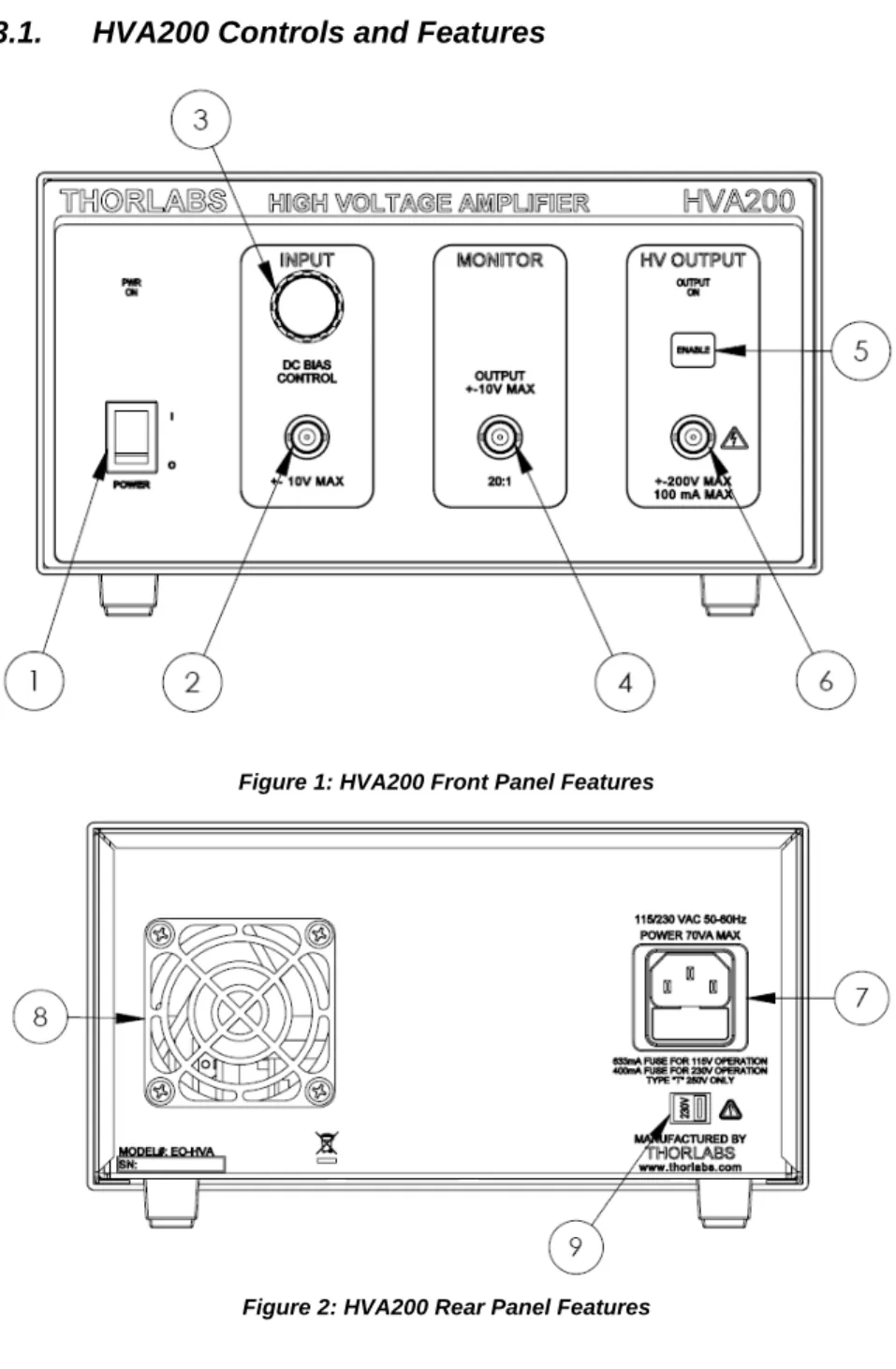
Legend Table for Facing Page
Legend Description 1 Main Power Switch
2 Modulation Input Signal - BNC 3 DC Bias Adjust Knob & Indicator Dial 4 HV Output Monitor - BNC
5 HV Enable Button
6 HV Output – BNC (DANGER, High Voltage) 7 AC Input Connector – IEC and Fuse Drawer
8 Cooling Fan
3.1.
HVA200 Controls and Features
Figure 1: HVA200 Front Panel Features
18014-D02 Rev B, Jan 26, 2009 Page 8 www.thorlabs.com
Part 4. HVA200 Specifications
Specification Description
Physical Features
Input Connector BNC (± 10V, 10 mA)
HV Output Connector2 BNC (± 200V, 100 mA)
HV Monitor Connector3 BNC (± 10V, 200 mA, Min Load 50 Ω)
Bias Adjustment Digital Encoder
Output Enable Front Panel Pushbutton
Output HV Indicator Bright LED
Power Switch Rocker Switch
Dimensions 9″ x 5″ x 12.5″ 228.6 mm x 127 mm x 317.5 mm
Weight 11.6 lbs
Other Tilting Rubber-Padded Feet
Max Ratings:
Max Output Current 100 mA DC
Max Input Voltage Range -10 to 10 V
Fuse Rating 630 mA @ 115 VAC (5x20 mm SLO-BLO) 400 mA @ 230 VAC (5x20 mm SLO-BLO) Operating Temperature Range 10 to 40°C, MAX 85% RH Electrical Characteristics
Max. Input Voltage Range -10 to 10 V
Input Impedance 1 kΩ Output Voltage -200 to 200 V Output Impedance 50Ω Slew Rate 400 V/μs Output Noise 1.5 mV RMS Voltage Gain1 -20 ± 2% DC Bias Adjust -200 to 200 V
HV Monitor to Output Ratio:
With Input Impedance of 50Ω 40:1 (Vout / 40 ± 6%) With Input Impedance of >10 kΩ 20:1 (Vout / 20 ± 6%)
HV Monitor Output Impedance 50Ω
AC Power 115V/230V, 50-60 Hz, 70 VA
1 The voltage gain is inverted to preserve the high slew rate of the output amplifier (i.e., a -1 V input results in +20 V output).
2 The HV output will handle an accidental short circuit without damage, but the output should not be shorted continuously.
3 The HV monitor output will handle accidental short circuits without damage, but must not be shorted for more than 5 sec to prevent excessive heating of the output resistor. The HV monitor output will source up to 200 mA when a short circuit is applied.
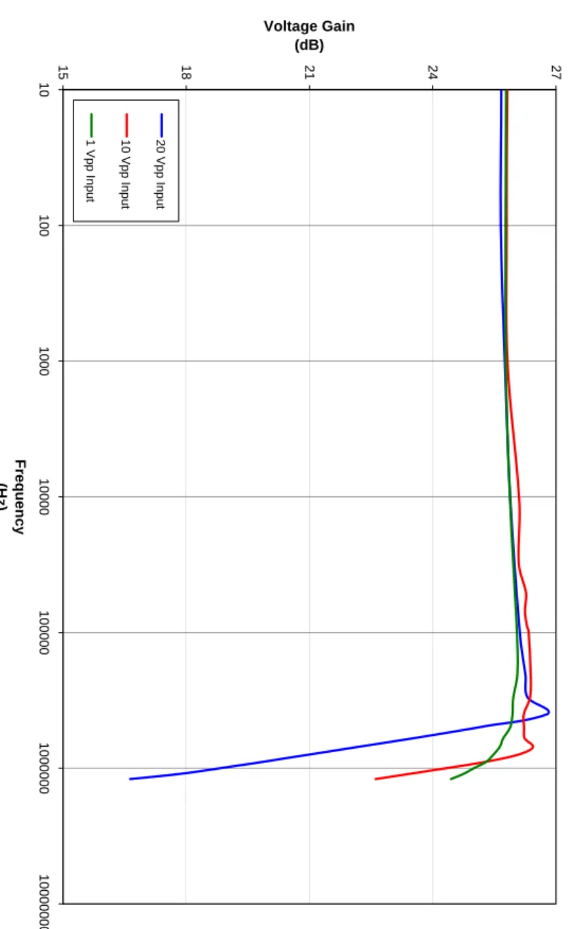
Figure 3: Typical Gain Bandwidth
Ty
p
ical Gain Band
w idt h 15 18 21 24 27 1 0 100 100 0 1 0 000 10 000 0 1 0 000 00 10 00 000 0 Fr eq u e nc y (H z) Voltage Gain (dB) 20 V pp In put 10 V pp In put 1 Vp p Inp u t
18014-D02 Rev B, Jan 26, 2009 Page 10 www.thorlabs.com
Part 5. Maintenance
The HVA200 amplifier needs very little maintenance under normal operating conditions. There are no serviceable parts in the HVA200. The enclosure may be cleaned by wiping with a soft damp cloth. If you suspect a problem with your HVA200 please call Thorlabs and technical support will be happy to assist you.
5.1. Fuse
Replacement
The AC input is protected by a fuse located in a pull out compartment drawer on the rear panel AC connector. Refer to Figure 2 on page 7. If replacement is needed, disconnect the power cord from the back of the amplifier and pull the fuse compartment drawer out to expose the fuse. A small screwdriver may be used to pry the drawer open.
Replace the fuse with the correct rating. Do not use a fuse with a current rating higher than the unit is rated for. The fuse ratings are as follows:
• 115V: 630 mA 5x20mm SLO-BLO
• 230V: 400 mA 5x20mm SLO-BLO
5.2. Ventilation
For proper operation and protection of the output amplifier, it is important that the ventilation passages located on the sides and rear of the unit not be obstructed from free airflow.
5.3. Troubleshooting
Problem Solutions
“PWR ON” not illuminating, unit is not functioning
Check that the power switch in the on position, the mains connection is correct,
and the fuse has not been damaged. Output will not enable, “OUTPUT ON” is
flashing
The amplifier has gone into a protection mode because the circuitry has sensed that
one of the HV supplies is not working correctly.
Part 6. Warranty Information
General Product Warranty
Thorlabs warrants that all products sold will be free from defects in material and workmanship, and will conform to the published specifications under normal use and service when correctly installed and maintained.
Opto-Mechanics
Lifetime Warranty: Thorlabs offers a lifetime warranty on all opto-mechanical components. Thorlabs will repair or replace any opto-mechanical product which after evaluation has failed to perform in the above conditions.
Optical Tables and Breadboards
Lifetime Warranty: We provide a lifetime guarantee that all of our passively damped optical tables and breadboards will meet all originally stated performance specifications under normal use and proper handling. We additionally guarantee that all our table tops and breadboards, both active and passive, will be free from defects in workmanship, including de-lamination of the skins under normal use and handling.
Lasers and Imaging Systems
Thorlabs offers a one year warranty on all lasers and imaging systems, with the exceptions of laser diodes. Some products are warranted for the number of hours specified in the operating manual of each laser.
Opto-Electronics, Control Electronics, Optics, and Nano-Positioning Product Lines Thorlabs offers a two year warranty on the above mentioned product lines, provided normal use and maintenance of the products and when properly handled and correctly installed. Thorlabs shall repair or replace any defective or nonconforming product as detailed above. We ask that buyer contact Thorlabs for a Return Material Authorization number (RMA #) from our Customer Service/Returns department in order to most efficiently process the return and/or repair.
Products returned for repair that are not covered under warranty, a Thorlabs standard repair charge shall be applicable in addition to all shipping expenses. This repair charge will be quoted to the customer before the work is performed.
Warranty Exclusions
The stated warranty does not apply to Products which are (a) specials, modifications, or customized items (including custom patch cables) meeting the specifications you provide; (b) ESD sensitive items whose static protection packaging has been opened; (c) items repaired, modified or altered by any party other than Thorlabs; (d) items used in conjunction with equipment not provided by, or acknowledged as compatible by, Thorlabs; (e) subjected to unusual physical, thermal, or electrical stress; (f) damaged due to improper installation, misuse, abuse, or storage; (g) damaged due to accident or negligence in use, storage, transportation or handling.
18014-D02 Rev B, Jan 26, 2009 Page 12 www.thorlabs.com
Part 7. Declaration of Conformity
Part 8. Regulatory
As required by the WEEE (Waste Electrical and Electronic Equipment Directive) of the European Community and the corresponding national laws, Thorlabs offers all end users in the EC the possibility to return “end of life” units without incurring disposal charges.
• This offer is valid for Thorlabs electrical and electronic equipment:
• Sold after August 13, 2005
• Marked correspondingly with the crossed out “wheelie bin” logo (see right)
• Sold to a company or institute within the EC
• Currently owned by a company or institute within the EC
• Still complete, not disassembled and not contaminated
As the WEEE directive applies to self contained operational electrical and electronic products, this end of life take back service does not refer to other Thorlabs products, such as:
• Pure OEM products, that means assemblies to be built into a unit by the user (e.g. OEM laser driver cards)
• Components
• Mechanics and optics
• Left over parts of units disassembled by the user (PCB’s, housings etc.). If you wish to return a Thorlabs unit for waste recovery, please contact Thorlabs or your nearest dealer for further information.
8.1.
Waste Treatment is Your Own Responsibility
If you do not return an “end of life” unit to Thorlabs, you must hand it to a company specialized in waste recovery. Do not dispose of the unit in a litter bin or at a public waste disposal site.
8.2. Ecological
Background
It is well known that WEEE pollutes the environment by releasing toxic products during decomposition. The aim of the European RoHS directive is to reduce the content of toxic substances in electronic products in the future.
The intent of the WEEE directive is to enforce the recycling of WEEE. A controlled recycling of end of live products will thereby avoid negative impacts on the environment.
18014-D02 Rev B, Jan 26, 2009 Page 14 www.thorlabs.com