Buoyancy-driven heat transfer enhancement
in a two-dimensional enclosure utilizing nanofluids
Khalil Khanafer
a,b, Kambiz Vafai
a,*, Marilyn Lightstone
baMechanical Engineering Department, University of California, A363 Bourns Hall, Riverside, CA 92521-0425, USA bMechanical Engineering Department, McMaster University, Hamilton, Canada L8S 4L7
Received 26 November 2002; received in revised form 8 March 2003
Abstract
Heat transfer enhancement in a two-dimensional enclosure utilizing nanofluids is investigated for various pertinent parameters. A model is developed to analyze heat transfer performance of nanofluids inside an enclosure taking into account the solid particle dispersion. The transport equations are solved numerically using the finite-volume approach along with the alternating direct implicit procedure. Comparisons with previously published work on the basis of special cases are performed and found to be in excellent agreement. The effect of suspended ultrafine metallic nano-particles on the fluid flow and heat transfer processes within the enclosure is analyzed and effective thermal conductivity enhancement maps are developed for various controlling parameters. In addition, an analysis of variants based on the thermophysical properties of nanofluid is developed and presented. It is shown that the variances within different models have substantial effects on the results. Finally, a heat transfer correlation of the average Nusselt number for various Grashof numbers and volume fractions is presented.
Ó 2003 Elsevier Ltd. All rights reserved.
1. Introduction
Nanotechnology is considered by many to be one of the significant forces that drive the next major industrial revolution of this century. It represents the most rele-vant technological cutting edge currently being explored. It aims at manipulating the structure of the matter at the molecular level with the goal for innovation in virtually every industry and public endeavor including biological sciences, physical sciences, electronics cooling, trans-portation, the environment and national security.
Low thermal conductivity of conventional heat transfer fluids such as water, oil, and ethylene glycol mixture is a primary limitation in enhancing the per-formance and the compactness of many engineering electronic devices. To overcome this drawback, there is a strong motivation to develop advanced heat transfer
fluids with substantially higher conductivities to enhance thermal characteristics. Small particles (nanoparticles) stay suspended much longer than larger particles. If particles settle rapidly (microparticles), more particles need to be added to replace the settled particles, result-ing in extra cost and degradation in the heat transfer enhancement. As such an innovative way in improving thermal conductivities of a fluid is to suspend metallic nanoparticles within it. The resulting mixture referred to as a nanofluid possesses a substantially larger thermal conductivity compared to that of traditional fluids [1].
The presence of the nanoparticles in the fluids in-creases appreciably the effective thermal conductivity of the fluid and consequently enhances the heat transfer characteristics. Nanofluids have a distinctive character-istic, which is quite different from those of traditional solid–liquid mixtures in which millimeter and/or micro-meter-sized particles are involved. Such particles can clot equipment and can increase pressure drop due to settling effects. Moreover, they settle rapidly, creating substantial additional pressure drop. However, nano-fluids exhibit little or no penalty in pressure drop when
*
Corresponding author. Tel.: 787-2135; fax: +1-909-787-2899.
E-mail address:[email protected](K. Vafai).
0017-9310/03/$ - see front matterÓ 2003 Elsevier Ltd. All rights reserved.
doi:10.1016/S0017-9310(03)00156-X
flowing through the passages. Moreover, they flow smoothly through microchannels without clogging them. Thus, nanofluids are best for applications in which fluid flows through small passages because nanoparticles are small enough to behave similar to liquid molecules. Nanofluids show promise in signifi-cantly increasing heat transfer rates in a variety of ap-plications, with minimum pressure drop. Enhancements were recently reported for copper Cu nanofluids, where just a 0.3% volume fraction of 10 nm diameter copper Cu nanoparticles led to an increase of up to 40% in the thermal conductivity of ethylene glycol [2]. This can be attributed to several factors such as nanoparticle clus-tering [3], ballistic phonon transport [3], layering at the solid/liquid interface [3], the interaction and collision among particles and surface area enhancement. In ad-dition, the suspended particles increase the surface area and the heat capacity of the fluid. That is, a significant improvement in the effective thermal conductivity is achieved as a result of decreasing the size of the sus-pended particles (nano-sized particle) rather than using larger particles (micro-sized particle). Since heat transfer occurs on the surface of a solid, this feature greatly en-hances the fluidÕs heat conduction contribution. Wang et al. [4] studied the thermal conductivity of nano-sized SiC suspensions using a transient hot-wire method. Their experimental results showed that the thermal conductivities of the studied suspensions were increased
and the enhancement was proportional to the volume fraction of the solid phase. The dependence of the thermal conductivity of nanoparticle–fluid mixture on the base fluid was analyzed by Xie et al. [5].
When simulating heat transfer enhancement using nanofluids, modeling of the effective thermal conduc-tivity possesses a challenge. This can be attributed to several factors such as gravity, Brownian motion, fric-tion force between the fluid and the ultrafine solid particles, sedimentation, layering at the solid/liquid interface, ballistic phonon transport through the parti-cles and the clustering of nanopartiparti-cles. This implies that the slip velocity between the fluid phase and the nano-particles is not zero, although the nano-particles are ultrafine. A body of theoretical work in the literature [6–8] is available on the effective thermal conductivity of two-phase mixtures that contain powders with particle dia-meters in the order of millidia-meters or even microdia-meters since the first published theoretical work by Maxwell [9]. MaxwellÕs model predicted that the effective thermal conductivity of suspensions containing spherical parti-cles increases with an increase in the volume fraction of the solid particles. Hamilton and Crosser [10] investi-gated the possibility of increasing particle surface area by controlling particle shapes to be non-spherical. Ap-proximately, an order of magnitude improvement in surface area per particle volume was achieved experi-mentally using this approach alone. The authors devel-Nomenclature
A aspect ratio,L=H
cp specific heat at constant pressure
dp nanoparticle diameter
~gg gravitational acceleration vector
Gr Grashof number,gbfDTH3=m2f
H cavity height
kf fluid thermal conductivity
ks solid thermal conductivity
L cavity width
Nu average Nusselt number
Pr Prandtl number,mf=af
Q total heat transfer from the left wall
t time
T temperature
U,V dimensionless interstitial velocity
compo-nents
u,v interstitial velocity components
x,y Cartesian coordinates
X,Y dimensionless coordinates
Greek symbols
a thermal diffusivity
bf fluid thermal expansion coefficient
bs solid expansion coefficient
/ solid volume fraction
mf kinematic viscosity h dimensionless temperature, ðTTLÞ= ðTHTLÞ x vorticity X dimensionless vorticity, ffiffiffiffiffiffiffiffiffiffiffiffiffixH gbfDTH3 p w stream function
W dimensionless stream function, w
H ffiffiffiffiffiffiffiffiffiffiffiffiffigbfDTH3
p
d variable used in Eq. (19)
q density s dimensionless time,t ffiffiffiffiffiffiffiffiffiffiffiffiffi gbfDTH3 p H l dynamic viscosity Subscripts eff effective f fluid H hot L cold nf nanofluid o reference value s solid
oped an expression for the effective thermal conductivity of two-component mixtures as a function of liquid and solid particle thermal conductivities, particle volume fraction, and an empirical scaling factor that takes into account the effect of different particle shapes on the ef-fective thermal conventional solid particles suffer from significant clogging problems due to their significant size conductivity. An alternative expression for calculating the effective thermal conductivity of solid–liquid mix-tures with a sphericity of one was established by Wasp [11].
Two main approaches have been adopted in the lit-erature to investigate the heat transfer enhancement by small solid particles (millimeter and/or micrometer-sized particles) suspended in a fluid. The first approach is the two-phase model, which enables a better understanding of both the fluid and the solid phases role in the heat transfer process. The second approach is the single-phase model in which both the fluid single-phase and the particles are in thermal equilibrium state and flow with the same local velocity. The latter approach is simpler and more computationally efficient. Several factors may affect heat transfer enhancement using nanofluids. These factors include gravity, Brownian motion, layering at the solid/liquid interface, ballistic phonon transport through the particles, nanoparticles clustering, and the friction between the fluid and the solid particles. The phenomena of Brownian diffusion, sedimentation, and dispersion may coexist in the main flow of a nanofluid. In the absence of any experimental data and suitable theoretical studies in the literature to investigate these factors, the existing macroscopic two-phase model is not applicable for analyzing nanofluids. Accordingly the modified single-phase, taking into the account some of the above factors, is more convenient than the two-phase model if the main interest is focused on the heat transfer process. Moreover, superior characteristics of the nanofluid allow it to behave more like a fluid than the conventional solid–fluid mixtures.
The chaotic movement of the ultrafine particles in-creases the energy exchange rates in the fluid, i.e., ther-mal dispersion takes place within the flow of the nanofluid. To account for the random motion of the particles, dispersion model is implemented. So far, there is a lack of theoretical and experimental works published on the thermal diffusivity coefficients of nanofluids. Thermal diffusivity coefficient for nanofluid can be modeled similar to the thermal dispersion models for flow through porous media. The dispersed model was first applied by Taylor [12] to simulate salt diffu-sion in water. Xuan and Li [13] presented a proce-dure for preparing a nanofluid which is a suspension consisting of nanophase powders and a base liquid. Later on, Xuan and Roetzel [14], analyzed theoreti-cally the flow of a nanofluid inside a tube using a dis-persion model. Recently, Keblinski et al. [3] investigated
the mechanisms of heat flow in suspensions of nano-sized particles (nanofluids). Four possible explana-tions were reported for an increase in the thermal conductivity with decreasing grain size. They devel-oped a fundamental understanding of heat transport in solid nanoparticle colloids under stationery condi-tions.
To the best knowledge of the authors, the problem of buoyancy-driven heat transfer enhancement of nano-fluids in a two-dimensional enclosure has not been ana-lyzed. This problem may be encountered in a number of electronic cooling and MEMS applications. The present study is focused on the analysis of several pertinent parameters on the heat transfer characteristics of nano-fluids within the enclosure. The dispersion effect is analyzed in the present investigation. Effective thermal conductivity maps will be developed in the present study for various pertinent parameters.
2. Mathematical formulation
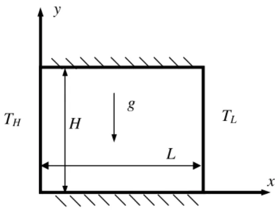
Consider a two-dimensional enclosure of height H
and widthL filled with a nanofluid as shown in Fig. 1. The horizontal walls are assumed to be insulated, non-conducting, and impermeable to mass transfer. The nanofluid in the enclosure is Newtonian, incompressible, and laminar. The nanoparticles are assumed to have a uniform shape and size. Moreover, it is assumed that both the fluid phase and nanoparticles are in thermal equilibrium state and they flow at the same velocity. The left vertical wall is maintained at a high temperature ðTHÞ while the right vertical wall is kept at a low tem-perature ðTLÞ. The thermophysical properties of the nanofluid are assumed to be constant except for the density variation in the buoyancy force, which is based on the Boussinesq approximation.
The initial and boundary conditions for the present investigation are presented as
y
x
T
LT
Hg
H
L
u¼v¼T ¼0 fort¼0 ð1Þ u¼v¼oT oy¼0 aty¼0;H and 06x6L T ¼TH; u¼v¼0 atx¼0; 06y6H T ¼TL; u¼v¼0 atx¼L; 06y6H 3 7 5 fort>0 ð2Þ
The governing equations for the present study taking into the account the above mentioned assumptions are written in dimensional form as
Vorticity equation ox ot þu ox oxþv ox oy ¼ leff qnf;o r2 xþ 1 qnf;o ½/qs;obs þ ð1/Þqf;obfg oT ox ð3Þ Energy equation oT ot þu oT oxþv oT oy¼ o ox anf þ kd ðqcpÞnf o T ox þ o oy anf þ kd ðqcpÞnf oT oy ð4Þ Kinematics equation o2w ox2 þ o2w oy2 ¼ x ð5Þ
whereanf¼ ðkeffÞstagnant=ðqcpÞnf.
The effective density of a fluid containing suspended particles at a reference temperature is given by
qnf;o¼ ð1/Þqf;oþ/qs;o ð6Þ where qf;o, qs;o, and / are the density of clear fluid, density of the particles, and the volume fraction of the nanoparticles, respectively. The effective viscosity of a fluid of viscosity lf containing a dilute suspension of small rigid spherical particles is given by Brinkman [15] as
leff¼ lf
ð1/Þ2:5 ð7Þ
The heat capacitance of the nanofluid can be presented as
ðqcpÞnf¼ ð1/ÞðqcpÞfþ/ðqcpÞs ð8Þ The effective stagnant thermal conductivity of the solid– liquid mixture was introduced by Wasp [11] as follows ðkeffÞstagnant
kf
¼ksþ2kf2/ðkfksÞ
ksþ2kfþ/ðkfksÞ
ð9Þ This equation is applicable for the two-phase mixture containing micro-sized particles. In the absence of any convenient formula for the calculations of the stagnant thermal conductivity of nanofluids, Eq. (9) may ap-proximately apply to obtain a reasonable estimation.
The effective thermal conductivity of the nanofluid may take the following form
keff¼ ðkeffÞstagnantþkd ð10Þ
Therefore, the enhancement in the thermal conductivity due to the thermal dispersion is given as [16]
kd¼CðqcpÞnfjVj/dp ð11Þ
where jVj ¼pffiffiffiffiffiffiffiffiffiffiffiffiffiffiu2þv2 and C is an unknown constant which should be determined by matching experimental data. The above equations can be cast in non-dimen-sional form by incorporating the following dimension-less parameters X ¼x H; Y¼ y H; U¼ u ffiffiffiffiffiffiffiffiffiffiffiffiffi gbfDTH3 p ; V ¼ ffiffiffiffiffiffiffiffiffiffiffiffiffiv gbfDTH3 p ; s¼t ffiffiffiffiffiffiffiffiffiffiffiffiffi gbfDTH3 p H ; X¼ xH ffiffiffiffiffiffiffiffiffiffiffiffiffi gbfDTH3 p ; W¼ w H ffiffiffiffiffiffiffiffiffiffiffiffiffigbfDTH3 p ; h¼ TTL THTL; 9 > > > > > = > > > > > ; ð12Þ oX osþU oX oXþV oX oY ¼ r 2X ð1/Þ2:5 /qs;o qf;oþ ð1/Þ h i ffiffiffiffiffiffi Gr p þkoh oX ð13Þ oh osþU oh oXþV oh oY¼ 1 PrpffiffiffiffiffiffiGr o oX v oh oX þ o oY v oh oY ð14Þ o2W oX2þ o2W oY2 ¼ X ð15Þ where v¼ ðkeffÞstagnant kf h i ð1/Þ þ/ðqcpÞs ðqcpÞf þC/dp HPr ffiffiffiffiffiffi Gr p ffiffiffiffiffiffiffiffiffiffiffiffiffiffiffiffiffi U2þV2 p ð16Þ
In the above equations,Gr¼gbfDTH3=v2f is the Grashof number,Pr¼vf=af is the Prandtl number and/is the volume fraction of the nanoparticles. The aspect ratio is defined asA¼L=H and is assumed unity in this inves-tigation. The diameter of the nanoparticledpis taken as 10 nm in the present study. The physical dimension of the enclosureHis chosen to be 1 cm.
The coefficientkthat appears next to the buoyancy term is given as k¼ 1 1þð1//Þqf;o qs;o bs bf 2 4 þ 1 1þ / ð1/Þ qs;o qf;o 3 5¼bnf bf ð17Þ
The Nusselt number of the nanofluids is expected to depend on a number of factors such as thermal con-ductivity and heat capacitance of both the pure fluid and ultrafine particles, the volume fraction of the suspended
particles, the dimensions of these particles, flow struc-ture, and the viscosity of the nanofluid. The local vari-ation of the Nusselt number of the nanofluid can be expressed as Nu¼ Q Qcond;fluid ¼ ðkeffÞstagnant kf oh oX ð18Þ where Q¼ ðkeffÞstagnantA oT oxjx¼0 3. Numerical method
The governing equations (13)–(15) were discretized using a finite volume approach [17]. A brief description of the numerical approach is presented here. The gov-erning equations can be represented by a general dif-ferential equation as follows
du ou osþ o oX Uu Cu ou oX þ o oY Vu Cu ou oY ¼Su ð19Þ whereustands for eitherXorhwith
dX¼1; CX¼ 1 ð1/Þ2:5 /qs;o qf;oþ ð1/Þ h i ffiffiffiffiffiffi Gr p ; SX¼koh oX ð20Þ dh¼1; Ch¼ v PrpffiffiffiffiffiffiGr; Sh¼ 1 PrpffiffiffiffiffiffiGr ov oX oh oX þov oY oh oY ð21Þ The transient finite difference equations, Eqs. (13) and (14), were solved using an alternating direct implicit (ADI) algorithm in conjunction with the power-law 0 0.2 0.4 0.6 0.8 1 0 0.2 0.4 0.6 0.8 1 X Te m p er at u re 0 0.2 0.4 0.6 0.8 1 -0.05 -0.04 -0.03 -0.02 -0.01 0 0.01 0.02 0.03 0.04 0.05 U-Velocity Y -0.1 -0.06 -0.02 0.02 0.06 0.1 0 0.2 0.4 0.6 0.8 1 X V-Ve lo c ity 31 31 41 41 61 61 81 81 31 31 41 41 61 61, 81 81 41 41 61 61 81 81 31 31 × × × × × × × × × × × ×
Fig. 2. Velocity and temperature profiles at mid-sections of the
cavity for various mesh sizes (Gr¼105,Pr¼6:2,/¼5%).
Fig. 3. Comparison of the streamlines and the isotherms
be-tween the present work and that of Fidap [18] (Pr¼0:7,
technique [17]. In addition, false transient accelerator was implemented to expedite the convergence rate of the solution towards steady state condition. Furthermore, successive over relaxation (SOR) method was applied to solve for flow kinematics, as described by Eq. (15).
The vorticity on the boundaries is presented from its definition in terms of the primitive velocity variables as
Xi;1¼ ð4Ui;2þUi;3Þ 2DY ; Xi;N¼ ð4Ui;N1Ui;N2Þ 2DY ; X1;j¼ ð4V2;jV3;jÞ 2DX ; XM;j¼ ð4VM1;jþVM2;jÞ 2DX 9 > = > ; ð22Þ To test and assess grid independence of the solution scheme, numerical experiments were performed as shown in Fig. 2. These experiments show that an equally spaced grid mesh of 6161 is adequate to describe the flow and heat and mass transfer processes correctly. Further increase in the number of grid points produced essentially the same results. The validation of our in-house numerical code was performed against the results generated by a commercial package [18] for pure fluid as shown in Figs. 3–6. It can be seen from these figures that the solution of the present numerical code is in excellent agreement with the numerical results fromFIDAP[18]
for various Rayleigh numbers. Comparison of the so-lution with previous works for different Rayleigh num-bers is shown in Table 1. The comparison is concerned with the average Nusselt number along the hot wall, maximum and minimum velocity values and their cor-responding locations. This table shows an excellent agreement between the present results and other bench-mark solutions. Moreover, the present numerical code was also validated against the experimental results of Krane and Jessee [23] for natural convection in an en-closure filled with air as shown in Fig. 7. It can be seen from the comparison that both solutions are in a very good agreement.
4. Discussion
The numerical code developed in the present inves-tigation is used to carry out a number of simulations for a wide range of controlling parameters such as Grashof number and the volume fraction of particles. The range of the Grashof numberGrfor this investigation is varied between 1036Gr6105. The range of the volume frac-tion/used in this study is varied between 06/625%. The thermophysical properties of fluid and the solid phases are shown in Table 2.
Fig. 4. Comparison of the streamlines and the isotherms
be-tween the present work and that of Fidap [18] (Pr¼0:7,
Ra¼104).
Fig. 5. Comparison of the streamlines and the isotherms
be-tween the present work and that of Fidap [18] (Pr¼0:7,
To show that nanofluids behave more like a fluid than the conventional solid–fluid mixture, a comparison of the temperature and the velocity profiles is conducted inside a thermal cavity with isothermal vertical walls at
various Grashof numbers and volume fractions as shown in Fig. 8. This figure shows that the nanofluid behaves more like a fluid than the conventional solid– fluid mixtures in which relatively larger particles with
0 0.2 0.4 0.6 0.8 1 -0.8 -0.6 -0.4 -0.2 0 0.2 0.4 0.6 0.8 Temperature Y -1 -0.6 -0.2 0.2 0.6 1 0 0.2 0.4 0.6 0.8 1 X T e m p er at u re 0 0.2 0.4 0.6 0.8 1 -0.3 -0.2 -0.1 0 0.1 0.2 0.3 U-Velocity Y -0.5 -0.25 0 0.25 0.5 0 0.2 0.4 0.6 0.8 1 X V-Ve loc it y Ra=103 Ra=105 Ra=104 X=0.5 Ra=103 Ra=105 Ra=104 Y=0.5 Ra=103 Ra=104 Ra=105 Y=0.5 Ra=105 Ra=104 Ra=103 X=0.5 __ Present result _ _ Fidap [18] __ Present result _ _ Fidap [18] __ Present result
_ _ Fidap [18] __ Present result_ _ Fidap [18]
Fig. 6. Comparison of the temperature and velocity profiles at the mid-sections of the cavity between the present results and that of
Fidap [18]ðPr¼0:7Þ.
Table 1
Comparison of laminar solution with previous works for differentRa-values
Present Barakos and
Mitsoulis [19]
Markatos and Pericleous [20]
De Vahl Davis [21] Fusegi et al. [22]
Ra¼103 Nu 1.118 1.114 1.108 1.118 1.105 Umax(aty=H) 0.137 (0.812) 0.153 (0.806) – (0.832) 0.136 (0.813) 0.132 (0.833) Vmax(atx=H) 0.139 (0.173) 0.155 (0.181) – (0.168) 0.138 (0.178) 0.131 (0.200) Ra¼104 Nu 2.245 2.245 2.201 2.243 2.302 Umax(aty=H) 0.192 (0.827) 0.193 (0.818) – (0.832) 0.192 (0.823) 0.201 (0.817) Vmax(atx=H) 0.233 (0.123) 0.234 (0.119) – (0.113) 0.234 (0.119) 0.225 (0.117) Ra¼105 Nu 4.522 4.510 4.430 4.519 4.646 Umax(aty=H) 0.131 (0.854) 0.132(0.859) – (0.857) 0.153 (0.855) 0.147 (0.855) Vmax(atx=H) 0.258 (0.065) 0.258 (0.066) – (0.067) 0.261 (0.066) 0.247 (0.065) Ra¼106 Nu 8.826 8.806 8.754 8.799 9.012 Umax(aty=H) 0.077 (0.854) 0.077 (0.859) – (0.872) 0.079 (0.850) 0.084 (0.856) Vmax(atx=H) 0.262 (0.039) 0.262 (0.039) – (0.038) 0.262 (0.038) 0.259 (0.033)
millimeter or micrometer orders are suspended for var-ious Grashof number. Fig. 8 illustrates the effect of Grashof number and the volume fraction on the tem-perature and the velocity profiles at the mid-sections of the cavity for water with a Prandtl number of 6.2. The numerical results of the present study indicate that the heat transfer feature of a nanofluid increases remarkably with the volume fraction of nanoparticles. As the vol-ume fraction increases, irregular and random move-ments of particles increases energy exchange rates in the
Table 2
Thermophysical properties of different phases
Property Fluid phase
(water) Solid phase (copper) cp(J/kg K) 4179 383 q(kg/m3) 997.1 8954 k(W/m K) 0.6 400 b(K1) 2 .1104 1.67105 0 0.2 0.4 0.6 0.8 1 0 0.2 0.4 0.6 0.8 1 X T e mp eratu re 0 0.2 0.4 0.6 0.8 1 -0.2 -0.15 -0.1 -0.05 0 0.05 0.1 0.15 0.2 U-Velocity Y -0.4 -0.3 -0.2 -0.1 0 0.1 0.2 0.3 0.4 0 0.2 0.4 0.6 0.8 1 X V-Vel oci ty Experimental data [23]
Present numerical result
Fig. 7. Comparison of the temperature and the velocity profiles inside a thermal cavity with isothermal vertical walls between the present results and the experimental results by Krane and
Jessee [23] (Ra¼1:89105,Pr¼0:71). 0 0.2 0.4 0.6 0.8 1 0 0.2 0.4 0.6 0.8 1 X T e m p er atu re 0 0.2 0.4 0.6 0.8 1 -0.08 -0.06 -0.04 -0.02 0 0.02 0.04 0.06 0.08 U-Velocity Y -0.15 -0.1 -0.05 0 0.05 0.1 0.15 0 0.2 0.4 0.6 0.8 1 X V-V e lo ci ty Gr=105 Gr=104 =0, 0.1, 0.2 =0.2, 0.1,0 __ nanofluid _ _ pure fluid __ nanofluid _ _ pure fluid =0, 0.1, 0.2 =0.2, 0.1, 0 Gr=104 Gr=105 __ nanofluid _ _ pure fluid =0, 0.1, 0.2 Gr=104 Gr=105 =0.2, 0.1, 0 φ φ φ φ φ φ
Fig. 8. Comparison of the temperature and velocity profiles between nanofluid and pure fluid for various Grashof numbers
fluid and consequently enhances the thermal dispersion in the flow of nanofluid. In addition, the velocities at the center of the cavity for higher values of Grashof number are very small compared with those at the boundaries where the fluid is moving at higher velocities. This
be-havior is also present for a single-phase flow. As the volume fraction increases, the velocity components of nanofluid increase as a result of an increase in the energy transport through the fluid. High velocity peaks of the vertical velocity component are shown in this figure at
high volume fractions. The effect of an increase in the volume fraction on the velocity and temperature gradi-ents along the centerline of the cavity is shown in Fig. 8.
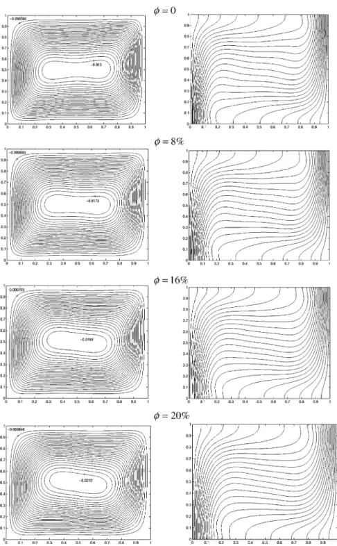
The effect of the volume fraction on the streamlines and isotherms of nanofluid for various Grashof numbers is shown in Figs. 9 and 10. In the absence of
ticles and for a low Grashof number ðGr¼103Þ, a central vortex appears as a dominant characteristic of
the fluid flow. As the Grashof number increases, as shown in Figs. 9 and 10ð/¼0Þ, the central vortex tends
Fig. 11. Comparison of the streamlines and isotherms contours between nanofluid (––) and pure fluid (- - -) at various Grashof
to become elliptic forGr¼104and eventually breaks up into three vortices for a Grashof number of Gr¼105. Figs. 9 and 10 show that the intensity of the streamlines
increase with an increase in the volume fraction as a result of high-energy transport through the flow asso-ciated with the irregular motion of the ultrafine particles.
In addition, for a Grashof number of 104, the central elliptic vortex of the streamline rotates clockwise as the volume fraction increases. This is associated with higher velocities along the centerline of the enclosure.
As the volume fraction increases, the velocities at the center of the cavity increase as a result of higher solid– fluid transportation of heat. Moreover, the velocities along the vertical walls of the cavity show a higher level of activity as predicted by thin hydrodynamic boundary layers. This is illustrated in the vertical velocity com-ponent variation along the horizontal centerline of the cavity for various volume fractions. The isotherms in Figs. 9 and 10 show that the vertical stratification of the isotherms breaks down with an increase in the volume fraction for higher Grashof numbers. This is due to a number of effects such as gravity, Brownian motion, ballistic phonon transport, layering at the solid/liquid interface, clustering of nanoparticles, and dispersion effect. In this study we considered only the effect of dispersion that may coexist in the main flow of a nanofluid.
A comparison of the streamlines and isotherms contours between nanofluid and the conventional fluid is conducted for various Grashof numbers and a volume
fraction of /¼10% as shown in Fig. 11. This figure
clearly shows the impact of the presence of nanoparticles on the isotherms for a low Grashof number. For a clear fluid, the isotherms at the center of the cavity are hori-zontal (stratification in the vertical direction) and be-come vertical only inside the thermal boundary layers at the vertical walls. The streamlines of a clear fluid show that the central vortex occupies a larger zone than that for nanofluid at a Grashof number of 104. For a Gras-hof number of 105, the central vortex does not breakup into three vortices as in the case of a clear fluid. This is associated with the dispersion effect.
The effective thermal conductivity enhancement contours of the nanofluid within the enclosure at dif-ferent Grashof numbers and volume fractions are shown in Fig. 12. This figure shows a significant enhancement in the effective thermal conductivity of nanofluid com-pared to the thermal conductivity of a clear fluid ððkeff;nfkfÞ=kfÞ.
5. Heat transfer correlation
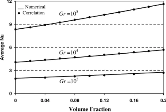
The average Nusselt number along the hot vertical wall is correlated in terms of the Grashof number ð1036Gr6105Þ and the particles volume fraction ð06/60:25Þ. Using the results from the present sim-ulations, the correlation can be expressed as
Nu¼0:5163ð0:4436þ/1:0809ÞGr0:3123 ð23Þ
where the confidence coefficient of the above equation is determined asR2¼99:9%. The average Nusselt number
along the hot wall from the correlation and the numer-ical results for various Grashof numbers and volume fractions is shown in Fig. 13. This figure shows a linear variation of the average Nusselt number with the void fraction. It should be noted that the trend in Fig. 13 for the average Nusselt number versus the volume fraction would be downward if the Nusselt number is based on the effective thermal conductivity, keff, instead of the fluid thermal conductivity, kf. The presence of nano-particles in the fluid enhances the Nusselt number by about 25% for Gr¼104 andGr¼105 at volume frac-tion of /¼0:2. This increase in the average Nusselt number plays a significant role in engineering applica-tions such as in electronic cooling.
6. Sensitivityto model properties
Different models based on the physical properties of nanofluid as displayed in Table 3 are examined with respect to variations of the average Nusselt number as a function of the volume fraction. These variations are based on different scenarios for the density, viscosity, and thermal expansion of nanofluid as shown in Table 2 and displayed in Fig. 14. All models used the effective thermal conductivity of nanoparticles in the present simulations. Fig. 14 gives the upper and lower bounds for the average nanofluid Nusselt number variations for different values of volume fractions. It can be seen that modeling of the density, viscosity and the thermal ex-pansion coefficient of nanofluid play a central role in heat transfer enhancement. Model III has the highest average Nusselt number among other models due to a higher thermal expansion and density, which results in a higher convection heat transfer. It should be noted that model IV has a lower average Nusselt number than model III due to a lower thermal expansion coefficient.
0 3 6 9 12 0 0.04 0.08 0.12 0.16 0.2 A v er ag e N u __Numerical Correlation Gr=104 Gr=105 Gr=103 Volume Fraction
Fig. 13. Comparison of the average Nusselt number between the numerical results and that obtained by the correlation ðPr¼6:2Þ.
Both models have the same nanofluid density and ef-fective viscosity except for the thermal expansion coef-ficient which is lower for model IV. As such, the resulting convection heat transfer for model IV is less than the one for model III. Model I has a higher average Nusselt number than model II due to a larger effective viscosity for model II resulting in a thicker momentum boundary layer and an increase in the shear stress be-tween the fluid layers. As such, the average Nusselt number for model II is lower than model I. Models II and III have the same effective viscosity and thermal expansion coefficient except that model III has a higher nanofluid density than model II. Higher effective density indicates higher momentum and consequently more heat transfer enhancement. Model IV is the one that is used as the default model earlier in the paper. It should be noted again that the trend in Fig. 14 for the average Nusselt number versus the volume fraction would be downward if the Nusselt number is based on the effective thermal conductivity, keff, instead of the fluid thermal conductivity,kf.
7. Conclusions
Heat transfer enhancement in a two-dimensional enclosure is studied numerically for a range of Grashof numbers and volume fractions. The present results il-lustrate that the suspended nanoparticles substantially increase the heat transfer rate at any given Grashof number. In addition, the results illustrate that the nanofluid heat transfer rate increases with an increase in the nanoparticles volume fraction. The presence of nanoparticles in the fluid is found to alter the structure of the fluid flow. A comparative study of different models based on the physical properties of nanofluid is analyzed in detail. The variances among these models are analyzed in the present study. The variants among models for the nanofluid density are found to be
sub-0 4 8 12 16 0 0.05 0.1 0.15 0.2 Avera g e Nu Gr=104 Gr=105 ) ( , , , ___ ) ( , , , __ _ I eff k f f f III eff k f eff eff ) ( , , , ) ( , , , _ . _ II eff k f eff f IV eff k nf eff eff (I) (II) (III) (IV) (I) (II) (III) (IV) Volume Fraction µ µ µ µ ρ ρ ρ ρ β β β β
Fig. 14. Average nanofluid Nusselt number variations for dif-ferent models. Table 3 Differen t mode ls of nano fluid density , visc osity, and therma l expan sion coeffi cient Model Density Visco sity Ther mal expan sion coeffi cient Non-d imensional viscou s term Non-d imensional buoy ancy term Phys ical basis I qf lf bf 1 ffiffiffiffiffiffi Gr p 1 Clear fluid II qf leff ¼ lf ð 1 / Þ 2 : 5 bf 1 ð 1 / Þ 2 : 5 ffiffiffiffiffi ffi Gr p 1 qf qs , / 6 5% III qeff ¼ /q s þð 1 / Þ qf leff ¼ lf ð 1 / Þ 2 : 5 bf 1 ð 1 / Þ 2 : 5 / qs; o qf; o þð 1 / Þ hi ffiffiffiffiffi ffi Gr p 1 / 6 0 : 5% IV qeff ¼ /q s þð 1 / Þ qf leff ¼ lf ð 1 / Þ 2 : 5 beff ¼ kb f 1 ð 1 / Þ 2 : 5 / qs; o qf; o þð 1 / Þ hi ffiffiffiffiffi ffi Gr p k ¼ 1 1 þ ð 1 / Þ / qf; o qs; o bs bf þ 1 1 þ / ð 1 / Þ qs; o qf; o 2 4 3 5 Gene ral model
stantial. Model III has the highest average Nusselt number. The variants among models for the effective viscosity are found to be more pronounced. Model I is found to have a higher average Nusselt number than model II. Finally, the variants among models for ther-mal expansion coefficient are found to be significant. A heat transfer correlation for the nanofluid is obtained and verified for various Grashof numbers and volume fractions. This work paves the way for a well-described systematic experimental investigation to better model nanofluids.
Acknowledgements
We acknowledge support of this work by DOD/ DARPA/DMEA under grant number DMEA 90-02-2-0216. The grant from National Sciences and Engineering
Research Council of Canada (NSERC-2002) is
ac-knowledged and appreciated.
References
[1] J.A. Eastman, S.U.S. Choi, S. Li, W. Yu, L.J. Thompson, Anomalously increased effective thermal conductivities of ethylene glycol-based nanofluids containing copper nano-particles, Appl. Phys. Lett. 78 (2001) 718–720.
[2] S.U.S. Choi, Enhancing thermal conductivity of fluids with nanoparticles, in: D.A. Siginer, H.P. Wang (Eds.), Devel-opments and Applications of Non-Newtonian Flows, FED-vol. 231/MD-vol. 66, ASME, New York, 1995, pp. 99–105.
[3] P. Keblinski, S.R. Phillpot, S.U.S. Choi, J.A. Eastman, Mechanisms of heat flow in suspensions of nano-sized particles (nanofluids), Int. J. Heat Mass Transfer 45 (2002) 855–863.
[4] X.W. Wang, X.F. Xu, S.U.S. Choi, Thermal conductivity of nanoparticle–fluid mixture, J. Thermophys. Heat Trans-fer 13 (1999) 474–480.
[5] H.Q. Xie, J.C. Wang, T.G. Xi, Y. Li, F. Ai, Dependence of the thermal conductivity of nanoparticle–fluid mixture on the base fluid, J. Mater. Sci. Lett. 21 (2002) 1469–1471. [6] Z. Hashin, S. Shtrikman, A variational approach to the
theory of the effective magnetic permeability of multiphase materials, J. Appl. Phys. 33 (1962) 3125–3131.
[7] R.H. Davis, The effective thermal conductivity of a composite material with spherical inclusion, Int. J. Ther-mophys. 7 (1986) 609–620.
[8] D.J. Jeffrey, Conduction through a random suspensions of spheres, Proc. R. Soc. Lond. A 335c (1973) 355–367. [9] J.C. Maxwell, A Treatise on Electricity and Magnetism,
second ed., Oxford University Press, Cambridge, 1904, pp. 435–441.
[10] R.L. Hamilton, O.K. Crosser, Thermal conductivity of heterogeneous two-component systems, I & EC Fundam. 1 (1962) 182–191.
[11] F.J. Wasp, Solid–liquid slurry pipeline transportation, Trans. Tech. Berlin, 1977.
[12] G.I. Taylor, Dispersion of soluble matter in solvent flowing through a tube, Proc. R. Soc. Col. A 219 (1953) 186–203. [13] Y. Xuan, Q. Li, Heat transfer enhancement of nanofluids,
Int. J. Heat Fluid Flow 21 (2000) 58–64.
[14] Y. Xuan, W. Roetzel, Conceptions for heat transfer correlation of nanofluids, Int. J. Heat Mass Transfer 43 (2000) 3701–3707.
[15] H.C. Brinkman, The viscosity of concentrated suspensions and solutions, J. Chem. Phys. 20 (1952) 571–581. [16] A. Amiri, K. Vafai, Analysis of dispersion effects and
non-thermal equilibrium, non-Darcian, variable porosity, in-compressible flow through porous media, Int. J. Heat Mass Transfer 37 (1994) 939–954.
[17] S.V. Patankar, Numerical Heat Transfer and Fluid Flow, Hemisphere, Washington, DC, 1980.
[18] FIDAP Theoretical Manual, Fluid Dynamics Interna-tional, Evanston, IL, 1990.
[19] G. Barakos, E. Mitsoulis, Natural convection flow in a square cavity revisited: laminar and turbulent models with wall functions, Int. J. Numer. Methods Fluids 18 (1994) 695–719.
[20] N.C. Markatos, K.A. Pericleous, Laminar and turbulent natural convection in an enclosed cavity, Int. J. Heat Mass Transfer 27 (1984) 772–775.
[21] G. De Vahl Davis, Natural convection of air in a square cavity, a benchmark numerical solution, Int. J. Numer. Methods Fluids 3 (1962) 249–264.
[22] T. Fusegi, J.M. Hyun, K. Kuwahara, B. Farouk, A numerical study of three-dimensional natural convection in a differentially heated cubical enclosure, Int. J. Heat Mass Transfer 34 (1991) 1543–1557.
[23] R.J. Krane, J. Jessee, Some detailed field measurements for a natural convection flow in a vertical square enclosure, Proceedings of the First ASME-JSME Thermal Engineer-ing Joint Conference, vol. 1, 1983, pp. 323–329.

![Fig. 5. Comparison of the streamlines and the isotherms be- be-tween the present work and that of Fidap [18] (Pr ¼ 0:7, Ra ¼ 10 5 ).](https://thumb-us.123doks.com/thumbv2/123dok_us/1312412.2675509/6.816.429.753.568.962/fig-comparison-streamlines-isotherms-tween-present-work-fidap.webp)
![Fig. 6. Comparison of the temperature and velocity profiles at the mid-sections of the cavity between the present results and that of Fidap [18] ðPr ¼ 0:7Þ.](https://thumb-us.123doks.com/thumbv2/123dok_us/1312412.2675509/7.816.135.681.108.482/comparison-temperature-velocity-profiles-sections-cavity-present-results.webp)