Data-Over-Cable Service Interface Specifications
DOCSIS 1.1
Operations Support System Interface Specification
CM-SP-OSSIv1.1-C01-050907
CLOSED
SPECIFICATION
Notice
This document is a cooperative effort undertaken at the direction of Cable Television Laboratories, Inc. (CableLabs®) for the benefit of the cable industry in general. Neither CableLabs nor any member company is responsible for any liability of any nature whatsoever resulting from or arising out of use or reliance upon this specification by any party. This document is furnished on an "AS IS" basis and neither CableLabs nor its members provides any representation or warranty, express or implied, regarding its accuracy, completeness, or fitness for a particular purpose.
© Copyright 1999-2005 Cable Television Laboratories, Inc. All rights reserved.
Document Status Sheet
Document Control Number: CM-SP-OSSIv1.1-C01-050907
Revision History: I01 – First Interim Release, April 7, 2000 I02 – Second Interim Release, July 14, 2000 I03 – Third Interim Release, December 15, 2000 I03 – Re-posting of I03, December 20, 2000 I04 – Fourth Interim Release, August 29, 2001 I05 – Fifth Issued Release, March 1, 2002 I06 – Sixth Issued Release, August 30, 2002 I07 – Seventh Issued Release, July 30, 2003 C01 – Closed September 7, 2005
Date: September 7, 2005
Status Code: Work in
Process
Draft Issued Closed
Distribution Restrictions: CableLabs & Members Only
CableLabs, Members, and Vendors Only
Public
Key to Document Status Codes
Work in Process An incomplete document, designed to guide discussion and generate feedback, that may include several alternative requirements for consideration.
Draft A document in specification format considered largely complete, but lacking review by Members and vendors. Drafts are susceptible to substantial change during the review process.
Issued A stable document which has undergone rigorous member and vendor review
and is suitable for product design and development, cross-vendor interoperability, and for certification testing.
Closed A static document, reviewed, tested, validated, and closed to further engineering change requests to the specification through CableLabs.
Trademarks:
DOCSIS® , eDOCSIS™, PacketCable™, CableHome®, OpenCable™ and CableLabs® are trademarks of Cable Television Laboratories, Inc.
Table of Contents
1 Scope and Purpose...1
1.1 SCOPE...1
1.2 REQUIREMENTS ...1
2 SNMP Protocol ...2
2.1 SNMP MODE FOR DOCSIS 1.1 COMPLIANT CMTS...2
2.1.1 KEY CHANGE MECHANISM ... 3
2.2 SNMP MODE FOR DOCSIS 1.1 COMPLIANT CMS...3
2.2.1 SNMPV3 INITIALIZATION AND KEY CHANGES ... 5
2.2.2 SNMPV3 INITIALIZATION... 5
2.2.3 DH KEY CHANGES ... 7
2.2.4 VACM PROFILE... 7
3 Management Information Bases (MIBs)...10
3.1 IPCDN DRAFTS AND OTHERS ... 10
3.2 IETF RFCS... 11
3.3 MANAGED OBJECTS REQUIREMENTS ... 11
3.3.1 CMTS MIB REQUIREMENTS ... 11
3.3.2 REQUIREMENTS FOR RFC-2669... 12
3.3.3 REQUIREMENTS FOR DOCS-IF-MIB... 12
3.3.4 REQUIREMENTS FOR RFC-2863... 13
3.3.5 INTERFACE MIB AND TRAP ENABLE... 15
3.3.6 REQUIREMENTS FOR RFC-2665... 15
3.3.7 REQUIREMENTS FOR RFC-1493... 16
3.3.8 REQUIREMENTS FOR RFC-2011... 16
3.3.9 REQUIREMENTS FOR RFC-2013... 16
3.3.10 REQUIREMENTS FOR RFC-3418... 16
3.3.11 REQUIREMENTS FOR DOCS-QOS-MIB ... 17
3.3.12 REQUIREMENTS FOR “DRAFT-IETF-IPCDN-IGMP-MIB-01.TXT”... 17
3.3.13 REQUIREMENTS FOR RFC-2933... 17
3.3.14 REQUIREMENTS FOR DOCS-BPI2-MIB ... 17
3.3.15 REQUIREMENTS FOR USB-MIB ... 17
3.3.16 REQUIREMENTS FOR DOCS-SUBMGT-MIB... 18
3.3.17 REQUIREMENTS FOR RFC-2786... 18
3.3.18 REQUIREMENTS FOR RFC-3083... 18
3.3.19 REQUIREMENT FOR DOCS-IF-EXT-MIB ... 19
3.3.20 REQUIREMENTS FOR DOCS-CABLE-DEVICE-TRAP-MIB ... 19
3.3.21 REQUIREMENTS FOR SNMPV3 MIBS... 19
3.4 CM CONFIGURATION FILES, TLV-11 AND MIB OIDS/VALUES... 19
3.4.1 CM CONFIGURATION FILE TLV-11 ELEMENT TRANSLATION (TO SNMP PDU)... 19
3.4.2 IGNORE CM CONFIGURATION TLV-11 ELEMENTS WHICH ARE NOT SUPPORTED BY CM 20 3.4.3 CM STATE AFTER CM CONFIGURATION FILE PROCESSING SUCCESS... 20
3.4.4 CM STATE AFTER CM CONFIGURATION FILE PROCESSING FAILURE... 21
3.5 TREATMENT AND INTERPRETATION OF MIB COUNTERS ON THE CM ... 21
3.6 CONFIG FILE ELEMENT – SNMP V3NOTIFICATION RECEIVER ... 21
3.6.1 MAPPING OF TLV FIELDS INTO CREATED SNMP V3 TABLE ROWS ... 22
4 OSSI for Radio Frequency Interface...29
4.1 SUBSCRIBER ACCOUNT MANAGEMENT INTERFACE SPECIFICATION ... 29
4.1.1 SERVICE FLOWS, SERVICE CLASSES, AND SUBSCRIBER USAGE BILLING ... 29
4.1.3 HIGH-LEVEL REQUIREMENTS FOR SUBSCRIBER USAGE BILLING RECORDS... 32
4.1.4 BILLING COLLECTION INTERVAL ... 33
4.1.5 BILLING FILE RETRIEVAL MODEL... 34
4.1.6 BILLING FILE SECURITY MODEL ... 35
4.1.7 IPDR RECORD STRUCTURE ... 36
4.2 CONFIGURATION MANAGEMENT ... 41
4.2.1 VERSION CONTROL... 41
4.2.2 SYSTEM INITIALIZATION AND CONFIGURATION ... 42
4.2.3 SECURE SOFTWARE UPGRADES ... 42
4.3 PROTOCOL FILTERS... 47 4.3.1 LLC FILTER... 47 4.3.2 SPECIAL FILTER ... 47 4.3.3 IP SPOOFING FILTER... 48 4.3.4 SNMP ACCESS FILTER ... 48 4.3.5 IP FILTER... 49 4.4 FAULT MANAGEMENT ... 49 4.4.1 SNMP USAGE... 49 4.4.2 EVENT NOTIFICATION ... 51
4.4.3 THROTTLING, LIMITING AND PRIORITY FOR EVENT, TRAP AND SYSLOG... 60
4.4.4 NON-SNMP FAULT MANAGEMENT PROTOCOLS... 61
4.5 PERFORMANCE MANAGEMENT... 61
4.5.1 ADDITIONAL MIB IMPLEMENTATION REQUIREMENTS ... 62
4.6 COEXISTENCE ... 62
4.6.1 COEXISTENCE AND MIBS, ... 63
4.6.2 COEXISTENCE AND SNMP ... 64
5 OSS for BPI+...65
5.1 DOCSIS ROOT CA... 65
5.2 DIGITAL CERTIFICATE VALIDITY PERIOD AND RE-ISSUANCE... 65
5.2.1 DOCSIS ROOT CA CERTIFICATE ... 65
5.2.2 DOCSIS MANUFACTURER CA CERTIFICATE ... 65
5.2.3 DOCSIS CM CERTIFICATE... 66
5.2.4 DOCSIS CODE VERIFICATION CERTIFICATE ... 66
5.3 CM CODE FILE SIGNING POLICY... 66
5.3.1 MANUFACTURER CM CODE FILE SIGNING POLICY... 66
6 OSSI for CMCI...68
6.1 SNMP ACCESS VIA CMCI ... 68
6.2 CONSOLE ACCESS ... 68
6.3 CM DIAGNOSTIC CAPABILITIES... 69
6.4 PROTOCOL FILTERING... 69
6.5 MANAGEMENT INFORMATION BASE (MIB) REQUIREMENTS ... 69
7 CM Operational Status Visualization...70
7.1 CM LEDS REQUIREMENTS AND OPERATION ... 70
7.1.1 POWER AND SELF TEST ... 71
7.1.2 SCANNING AND SYNCHRONIZATION TO DOWNSTREAM ... 71
7.1.3 DOCSIS UPSTREAM OBTAINING PARAMETERS... 71
7.1.4 BECOMING OPERATIONAL... 71
7.1.5 DATA LINK AND ACTIVITY ... 71
7.2 ADDITIONAL CM OPERATIONAL STATUS VISUALIZATION FEATURES ... 72
Appendix A. Detailed MIB Requirements ...73
Appendix B. RFC-2863 ifTable MIB-Object details...111
Appendix C. RFC-1493 and RFC-2863 MIB-Object Details for CCCM ...129
C.1RFC-1493 MIB-OBJECT DETAILS... 129
C.2IMPLEMENTATION OF RFC-1493 MIB FOR CCCM... 131
C.2.1 RFC-2863 IFTABLE MIB-OBJECT DETAILS FOR CCCM... 133
Appendix D. Business Process Scenarios For Subscriber Account Management ...134
D.1THE OLD SERVICE MODEL: “ONE CLASS ONLY” & “BEST EFFORT” SERVICE ... 134
D.2THE OLD BILLING MODEL: “FLAT RATE” ACCESS ... 134
D.3A SUCCESSFUL NEW BUSINESS PARADIGM ... 134
D.3.1 INTEGRATING “FRONT END” PROCESSES SEAMLESSLY WITH “BACK OFFICE” FUNCTIONS 134 D.3.2 DESIGNING CLASS OF SERVICES... 135
D.3.3 USAGE-BASED BILLING ... 136
D.3.4 DESIGNING USAGE-BASED BILLING MODELS... 136
Appendix E. IPDR Standards Submission for DOCSIS 1.1 Cable Data Systems Subscriber Usage Billing Records ...138
E.1SERVICE DEFINITION ... 138
E.1.1 DOCSIS SERVICE REQUIREMENTS ... 138
E.1.2 DOCSIS IPDR SERVICE USAGE ELEMENT LIST... 139
E.2DOCSIS-3.1-B.0.XSD – DOCSIS IPDR SCHEMA FILE... 145
E.3EXAMPLE IPDRDOC XML FILE CONTAINING DOCSIS SUBSCRIBER USAGE IPDRS ... 148
Appendix F. SNMPv2c INFORM Request Definition for Subscriber Account Management (SAM)...158
Appendix G. Summary of the CM Authentication and the Code File Authentication...159
G.1AUTHENTICATION OF THE DOCSIS 1.1 COMPLIANT CM... 159
G.1.1 RESPONSIBILITY OF THE DOCSIS ROOT CA ... 159
G.1.2 RESPONSIBILITY OF THE CM MANUFACTURERS ... 160
G.1.3 RESPONSIBILITY OF THE OPERATORS... 160
G.2AUTHENTICATION OF THE CODE FILE FOR THE DOCSIS 1.1 COMPLIANT CM... 160
G.2.1 RESPONSIBILITY OF THE DOCSIS ROOT CA ... 161
G.2.2 RESPONSIBILITY OF THE CM MANUFACTURER ... 161
G.2.3 RESPONSIBILITY OF CABLELABS ... 161
G.2.4 RESPONSIBILITY OF THE OPERATORS... 162
Appendix H. Format and Content for Event, SYSLOG and SNMP Trap...163
Appendix I. Trap Definitions for Cable Device ...185
Appendix J. Application of RFC-2933 to DOCSIS 1.1 active/passive IGMP devices ...186
J.1 DOCSIS 1.1 IGMP MIBS ... 186
J.1.1 IGMP CAPABILITIES: ACTIVE AND PASSIVE MODE... 186
J.1.2 IGMP INTERFACES... 186
J.2.1 IGMPINTERFACETABLE- IGMPINTERFACEENTRY ... 186
J.2.2 IGMPCACHETABLE - IGMPCACHEENTRY... 189
J.3 DOCSIS 1.1 CMTS SUPPORT FOR THE IGMP MIB ... 190
J.3.1 IGMPINTERFACETABLE- IGMPINTERFACEENTRY ... 191
J.3.2 IGMPCACHETABLE - IGMPCACHEENTRY... 194
J.3.3 IGMP MIB COMPLIANCE ... 195
J.3.4 MIB GROUPS... 196
Appendix K. Expected Behaviors for DOCSIS 1.1 modem in 1.0 and 1.1 modes in OSS area...197 Appendix L. DOCS-IF-EXT-MIB...200 Appendix M. DOCS-CABLE-DEVICE-TRAP-MIB ...203 Appendix N. References...225 Appendix O. Acknowledgements ...228 Appendix P. Revisions ...229
Figures
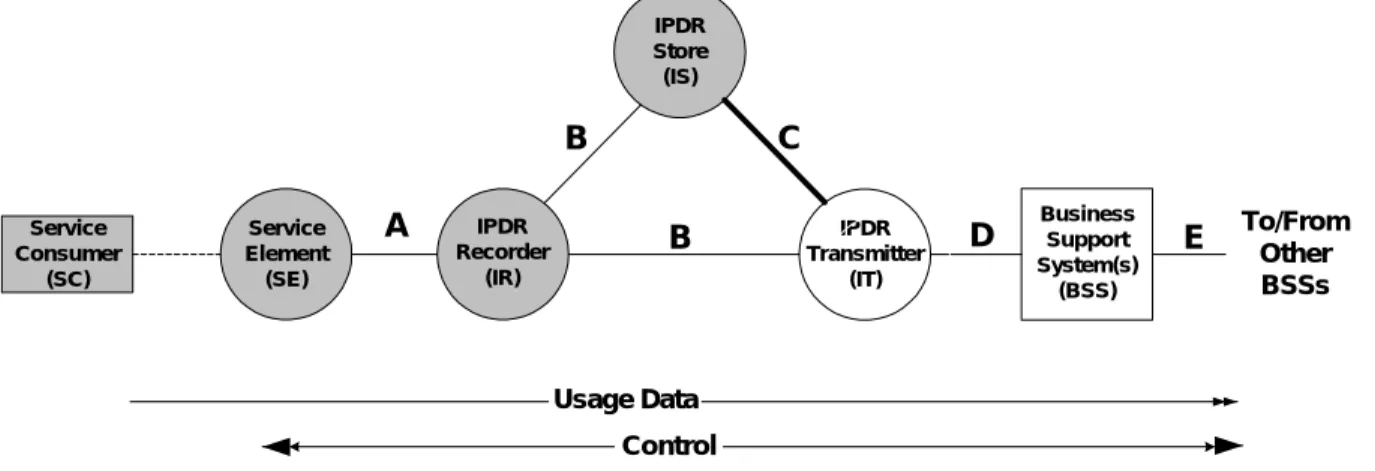
Figure 1. Ifindex Example for CMTS... 14Figure 2. Basic Network Model (ref. NDM-U 3.1 from www.ipdr.org) ... 31
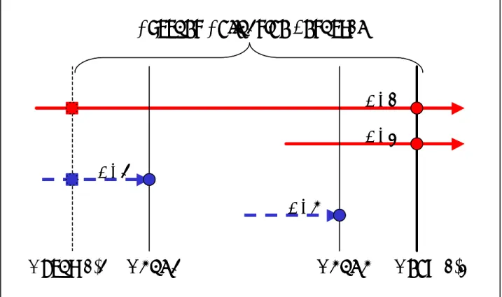
Figure 3. Billing Collection Interval Example... 34
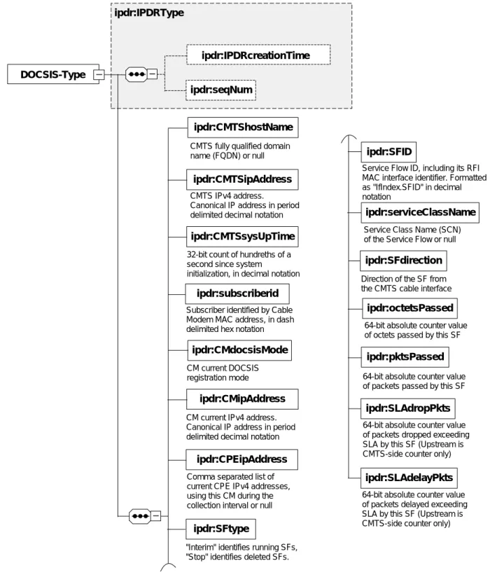
Figure 4. IPDRDoc 3.1 Generic Schema ... 36
Figure 5. DOCSIS IPDR 3.1 Schema ... 37
Figure 6. Manufacture control scheme ... 43
Figure 7. Operator control scheme. ... 43
Figure 8. Coexistent (DOCSIS 1.0 mode VS DOCSIS 1.1 mode)... 62
Figure 9. CM DOCSIS Mode and MIBs Requirement ... 63
Figure 10. Authentication of the DOCSIS 1.1 compliant CM ... 159
Tables
Table 1. IPCDN Drafts,, ... 10
Table 2. IETF RFCs ... 11
Table 3. CM Interface numbering ... 14
Table 4. docsIfCmStatusValue and ifOperStatus Relationship ... 15
Table 5. snmpNotifyTable ... 22
Table 6. snmpTargetAddrTable ... 23
Table 7. snmpTargetAddrExtTable ... 23
Table 8. snmpTargetParamsTable for <Trap type> 1, 2, or 3 ... 24
Table 9. snmp TargetParamsTable for ,Trap type> 4 or 5 ... 25
Table 10. snmpNotifyFilterProfileTable... 25 Table 11. snmpNotifyFilterTable ... 26 Table 12. snmpCommunityTable ... 26 Table 13. usmUserTable... 27 Table 14. vacmSecurityToGroupTable ... 27 Table 15. vacmAccessTable ... 28 Table 16. vacmViewTreeFamilyTable... 28
Table 17. Default event priorities for the Cable Modem Device, ... 57
Table 18. Default Event priorities for CMTS supporting only local-log non-volatile... 58
Table 19. Default Event priorities for CMTS supporting only local-log volatile ... 58
Table 20. Default Event priorities for CMTS supporting both local-log non-volatile and local-log volatile 59 Table 21. Event Priorities Assignment For CM and CMTSs... 59
Table 22. Maximum Level of Support for CM Events ... 60
Table 23. Maximum Level of Support for CMTS Events... 60
Table 24. Detailed MIB Requirements,,,,,, ... 75
Table 25. RFC-2863 ifTable MIB-Object details ... 111
Table 26. RFC-1493 MIB-Object Details ... 129
Table 27. The dot1dBase Group... 131
Table 28. Dot1dBasePortTable... 131
Table 29. The dot1dTp Group... 132
Table 30. dot1dFdbTable. ... 132
Table 31. dot1dTpPortTable. ... 132
Table 32. RFC-2863 ifTable MIB-Object details for CCCM. ... 133
Table 33. Service Usage Element Names ... 142
Table 34. Format and Content for Event, SYSLOG and SNMP Trap,,... 164
1 Scope and Purpose
1.1 Scope
This Specification defines the Network Management requirements for support a DOCSIS® 1.1
environment. More specifically, the specification details the SNMP v3 protocol and how it coexists with SNMP V1/V2. The RFCs and Management Information Base (MIB) requirements are detailed as well as interface numbering, filtering, event notifications, etc. Basic network management principals such as account, configuration, fault, and performance management are incorporated in this specification for better understanding of managing a high-speed cable modem environment.
1.2 Requirements
Throughout this document, the words that are used to define the significance of particular requirements are capitalized. These words are:
“MUST” This work or the adjective “REQUIRED” means that the item is an absolute requirement of this specification.
“MUST NOT” This phrase means that the item is an absolute prohibition of this specification. “SHOULD” This word of the adjective “RECOMMENDED” means that there may exist valid
reasons in particular circumstances to ignore this item, but the full implications should be understood and the case carefully weighted before choosing a different course.
“SHOULD NOT” This phrase means that there may exist valid reasons in particular circumstances when the listed behavior is acceptable or even useful, but the full implications should be understood and the case carefully weighed before implementing any behavior described with this label.
“MAY” This word or the adjective “OPTIONAL” means that this item is truly optional. One vendor may choose to include the item because a particular marketplace required it or because it enhances the product, for example; another vendor may omit the same item.
This document defines many features and parameters and a valid range for each parameter is usually specified. Equipment (CM and CMTS) requirements are always explicitly stated. Equipment must comply with all mandatory (MUST and MUST NOT) requirements to be considered compliant with this
2 SNMP
Protocol
The SNMPV3 protocol has been selected as the communication protocol for management of data-over-cable Services and MUST be implemented. Although SNMPv3 offers advantages, many management systems may not be capable of supporting SNMPV3 agents; therefore, support of SNMPv1 and SNMPv2c is also required and MUST be implemented.
The following IETF SNMP related RFCs MUST be implemented:
RFC-3410 Introduction and Applicability Statements for Internet Standard Management Framework
RFC-3411 An Architecture for Describing Simple Network Management Protocol (SNMP) Management Frameworks
RFC-3412 Message Processing and Dispatching for the Simple Network Management Protocol (SNMP)
RFC-3413 Simple Network Management Protocol (SNMP) Applications
RFC-3414 User-based Security Model (USM) for version 3 of the Simple Network Management Protocol (SNMPv3)
RFC-3415 View-based Access Control Model (VACM) for the Simple Network Management Protocol (SNMP)
RFC-3416 Version 2 of the Protocol Operations for the Simple Network Management Protocol (SNMP)
RFC-3417 Transport Mappings for the Simple Network Management Protocol (SNMP)
RFC-3418 Management Information Base (MIB) for the Simple Network Management Protocol (SNMP)
RFC-2576 Coexistence between Version 1, Version 2, and Version 3 of the Internet-standard Network Management Framework
RFC-1901 Introduction to Community-based SNMPv2 RFC-1157 A Simple Network Management Protocol
For support of SMIv2 the following IETF SNMP related RFCs MUST be implemented: RFC-2578 Structure of Management Information Version 2 (SMIv2)
RFC-2579 Textual Conventions for SMIv2 RFC-2580 Conformance Statements for SMIv2
For support of Diffie-Helman Key exchange for the User Based Security Model, the follow IETF SNMP related RFC MUST be implemented:
RFC-2786 Diffie-Helman USM Key Management Information Base and Textual Convention
2.1 SNMP Mode for DOCSIS 1.1 compliant CMTS
1DOCSIS 1.1 compliant CMTS MUST support SNMPv1, SNMPv2c, and SNMPv3 and SNMP coexistence as described by RFC-3411-RFC-2576 and MAY support SNMPv1, SNMPv2c vendor proprietary solutions, including SNMP v1/v2c NmAccess mode, with the following requirements:
a) DOCSIS 1.1 compliant CMTS MUST operate in SNMP coexistence mode (not using
docsDevNmAccessTable); additionally, SNMP coexistence mode MAY be disabled, by vendor
1
proprietary configuration control, to allow the CMTS to support SNMPv1, SNMPv2c vendor proprietary solutions, including SNMP v1/v2c NmAccess mode (using docsDevNmAccessTable). b) CMTS in SNMPv1/v2c NmAccess mode (using DOCS-CABLE-DEVICE-MIB docsDevNmAccess
Table) MUST operate with the following requirements/limitations: • Only SNMPv1/v2c packets are processed
• SNMPv3 pack3ets are dropped
• docsDevNmAccessTable controls SNMP access and SNMP trap destinations as described in RFC-2669
• None of the SNMPv3 MIBs as defined in [RFC-3411-3415] and [RFC-2576] are accessible.2 c) CMTS SNMPv1, SNMPv2c vendor proprietary solutions MUST operate with the following
requirements/limitations:
• Only SNMPv1/v2c packets are processed • SNMPv3 packets are dropped
• Vendor proprietary solution MUST control SNMP access and SNMP trap destinations • None of the SNMPv3 MIBs as defined in [RFC-3411-3415] and [RFC-2576] are accessible.3 d) CMTS SNMP Coexistence Mode MUST operate with the following requirements/limitations:
• SNMP v1/v2c/v3 Packets are processed as described by RFC-3411-3414 and RFC-2576. • docsDevNmAccessTable is not accessible. (If the CMTS also support
DOCS-CABLE-DEVICE-MIB)
• Access control and trap destinations are determined by the COMMUNITY-MIB, NOTIFICATION-MIB, TARGET-MIB, VIEW-BASED-ACM-MIB,
SNMP-COMMUNITY-MIB, and SNMP-USER-BASED-SM-MIB.
• The SNMP-COMMUNITY-MIB controls the translation of SNMPv1/v2c packet community string into securityName which select entries in the SNMP-USER-BASED-SM-MIB. Access control is provided by the SNMP-VIEW-BASED-ACM-MIB.
• The SNMP-USER-BASED-SM-MIB and SNMP-VIEW-BASED-ACM-MIB control SNMPv3 packets.
• Trap destinations are specified in the SNMP-TARGET-MIB and SNMP-NOTIFICATION-MIB.
2.1.1 Key Change Mechanism
DOCSIS 1.1 compliant CMTS SHOULD use the key-change mechanism specified in the RFC-2786. CMTS MUST always support the key-change mechanism described in the RFC-34144 to comply with industry-wide SNMP V3 standard.
2.2 SNMP Mode for DOCSIS 1.1 compliant CMs
5DOCSIS 1.1 compliant CMs (in 1.1 and 1.0 mode) MUST support SNMPv1, SNMPv2c and SNMPv3 as well as SNMP-coexistence (RFC-2576) with the following requirements:
a) Before completion of registration, the CM MUST operate as follows (in some CCCM
implementations, SNMP access MAY be made inaccessible from the CPE for security reasons; in
2
Revised this bullet statement per ECN OSS-N-03013 and 03066 by GO on 02/25/03 and 07/10/03.
3
Revised this bullet statement per ECN OSS-N-03013 and 03066 by GO on 02/25/03 and 07/10/03.
4
Revised RFC per ECN OSS-N-03066 by GO on 07/10/03.
5
such implementation, the access to similar set of MIB objects SHOULD be provided by a diagnostic utility as described in section 6.3):
• IP connectivity between the CM and the SNMP management station MUST implemented as described in section 6.1
• The CM MUST provide read-only access to the following MIB objects: docsIfDownChannelFrequency
docsIfDownChannelPower docsIfCmStatusValue docsDevServerBootState docsDevEventTable6
• The CM MAY provide read-only access to the following MIB objects sysDescr sysUptime ifTable ifXtable docsIfUpChannelFrequency docsIfSigQSignalQualityTable docsIfCmCmtsAddress docsIfCmStatusTxPower docsDevSwCurrentVers
• The CM MAY provide access to additional information, but MUST NOT reveal: CoS and QoS service flow information
configuration file contents
Secure Software Download information Key authentication and encryption material SNMP management and control
DOCSIS functional modules statistics and configuration Network provisioning hosts and servers IPs addresses. • Access from the RF interface MUST NOT be allowed
• SNMPv1/v2c packets are accepted which contain any community string • All SNMPv3 packets are dropped
• The registration request MUST be sent and registration MUST be completed after successful processing of all MIB elements in the config file, but before beginning the calculation of the public values in the USMDHKickstart Table.
b) The content of the CM config file determines the CM SNMP mode after registration
• CM is in SNMPv1/v2c docsDevNmAccess Mode if the CM configuration file contains ONLY docsDevNmAccessTable setting for SNMP access control.
• If configuration file does not contain SNMP access control items (docsDevNmAccessTable or snmpCommunityTable or TLV 34.1/34.2 orTLV38), then the CM is in NmAccess mode. • CM is in SNMP coexistence mode if the CM configuration file contains
- snmpCommunityTable setting and/or - TLV type 34.1 and 34.2. and/or - TLV type 38
- In this case, any entries made to the docsDevNmAccessTable are ignored.
c) After completion of registration - Modem operates in one of 2 modes. The operating mode is determined by the contents of the config file as described above.
6
SNMP V1/V2c NmAccess Mode (using docsDevNmAccess Table) • Only SNMP V1/V2c packets are processed
• SNMP V3 packets are dropped
• docsDevNmAccessTable controls access and trap destinations as described in RFC-2669 • None of the SNMP V3 MIBs as defined in [RFC-3411-3415] and [RFC-2576] are accessible.7 SNMP Coexistence Mode
During calculation of USMDHKickstartTable public values:
• The modem MUST NOT allow any SNMP access from the RF port
• The modem MAY continue to allow access from the CPE port with the limited access as configured by the SNMP-COMMUNITY-MIB, SNMP-TARGET-MIB, SNMP-VIEW-BASED-ACM-MIB and SNMP-USER-BASED-SM-MIB.
After calculation of USMDHKickstartTable public values:
• The modem MUST send the cold start or warm start trap to indicate that the modem is now fully SNMPv3 manageable.
• SNMP V1/V2c/V3 Packets are processed as described by RFC-3411-3415 and RFC-2576. • docsDevNmAccessTable is not accessible.
• Access control and trap destinations are determined by the COMMUNITY-MIB, NOTIFICATION-MIB, TARGET-MIB, VIEW-BASED-ACM-MIB,
SNMP-COMMUNITY-MIB and SNMP-USER-BASED-SM-MIB.
• The SNMP-COMMUNITY-MIB controls the translation of SNMPv1/v2c packet community string into security name which select entries in the SNMP-USER-BASED-SM-MIB. Access control is provided by the SNMP-VIEW-BASED-ACM-MIB.
• SNMP-USER-BASED-SM-MIB and SNMP-VIEW-BASED-ACM-MIB controls SNMPv3 packets. • Trap destinations are specified in the SNMP-TARGET-MIB and SNMP-NOTIFICATION-MIB. d) In case of failure to complete SNMPv3 initialization (i.e. NMS can not access CM via SNMPv3 PDU),
the CM is in the co-existence mode and will allow SNMPv1/v2c access if and only if the SNMP-COMMUNITY-MIB entries (and related entries) are configured.
2.2.1 SNMPv3 Initialization and Key changes 8
DOCSIS 1.1 compliant CM MUST support the “SNMPv3 Initialization” and “DH Key Changes” requirements specified in the following sections.
The DOCSIS 1.1 cable modem is designated as having "very-secure" security posture in the context of RFC-3414 Appendix A and RFC-3415 Appendix A. This means that default usmUser and vacmAccess entries defined in RFC-3414 Appendix A and RFC-3415 Appendix A MUST NOT be present.
2.2.2 SNMPv3 Initialization
1. For each of up to 5 different security names, the Manager generates a pair of numbers: a. Manager generates a random number Rm
7
Revised this bullet statement per ECN OSS-N-03013 by GO on 02/25/03.
8
b. Manager uses DH equation to translate Rm to a public number z
z = g ^ Rm MOD p where g is the from the set of Diffie-Hellman parameters, p is the prime from those parameters
2. CM configuration file is created to include (security name, public number) pair and CM MUST support a minimum of 5 pairs. For example:
TLV type 34.1 (SnmpV3 Kickstart Security Name) = docsisManager TLV type 34.2 (SnmpV3 Kickstart Public Number) = z
CM MUST support VACM entries defined in section 2.2.4 “VACM Profile”.
During the CM boot up process, the above values (security name, public number) will (MUST) be populated in the usmDHKickstartTable.
At this point:
usmDHKickstartMgrpublic.1 = “z” (octet string) usmDHKickstartSecurityName.1 = “docsisManager”
When usmDHKickstartMgrpublic.n is set with a valid value during the registration, a corresponding row is created in the usmUserTable with the following values:
usmUserEngineID: localEngineID
usmUserName: usmDHKickstartSecurityName.n value
usmuserSecurityName: usmDHKickstartSecurityName.n value usmUserCloneForm: ZeroDotZero
usmUserAuthProtocol: usmHMACMD5AuthProtocol usmuserAuthKeyChange: derived from set value usmUserOwnAuthKeyChange: derived from set value usmUserPrivProtocol: usmDESPrivProtocol
usmUserPrivKeyChange: derived from set value usmUserOwnPrivKeyChange: derived from set value usmUserPublic: ""
usmUserStorageType: permanent usmUserStatus: active
Note: For (CM) dhKickstart entries in usmUserTable, Permanent means it MUST be written to but not deleted and is not saved across reboots.
After the CM has registered with the CMTS.
1. CM generates a random number xa for each row populated in the usmDHKickstartTable which has a non zero length usmDHKickstartSecurityName and usmDHKickstartMgrPublic.
2. CM uses DH equation to translate xa to a public number c (for each row identified above)
c = g ^ xa MOD p where g is the from the set of Diffie-Helman parameters, p is the prime from those parameters
At this point:
usmDHKickstartMyPublic.1 = “c” (octet string) usmDHKickstartMgrPublic.1 = “z” (octet string) usmDHKickstartSecurityName.1 = “docsisManager” 3. CM calculate shared secret sk where sk = z ^xa mod p
4. CM uses sk to derive the privacy key and authentication key for each row in usmDHKickstartTable and sets the values into the usmUserTable
As specified in RFC-2786, the privacy key and the authentication key for the associated username, “docsisManager” in this case, is derived from sk by applying the key derivation function PBKDF2 defined in PKCS#5v2.0.
privacy key <--- PBKDF2( salt = 0xd1310ba6, iterationCount = 500, keyLength = 16,
prf = id-hmacWithSHA1)
authentication key <---- PBKDF2( salt = 0x98dfb5ac, iterationCount = 500,
keyLength = 16 (usmHMACMD5AuthProtocol), prf = id-hmacWithSHA1)
At this point the CM has completed its SNMPv3 initialization process and MUST allow appropriate access level to a valid securityName with the correct authentication key and/or privacy key. DOCSIS 1.1 compliant CM MUST properly populate keys to appropriate tables as specified by the SNMPv3 related RFCs and RFC-2786.
5. The following describes the process that the manager uses to derive CM’s unique authentication key and privacy key.
The SNMP manager accesses the contents of the usmDHKickstartTable using the security name of ‘dhKickstart’ with no authentication.
DOCSIS 1.1 compliant CM MUST provide preinstalled entries in the USM table and VACM tables to correctly create user ‘dhKickstart’ of security level noAuthnoPriv that has read only access to system group and usmDHkickstartTable.
SNMP manager gets the value of CM’s usmDHKickstartMypublic number associated with the security name that manager wants to derive authentication and privacy keys for. With the manager’s knowledge of the private random number, the manager can calculate the DH shared secret. From that shared secret, the manager can derive operational authentication and confidentiality keys for the security name that the manager is going to use to communicate with the CM.
2.2.3 DH Key Changes
DOCSIS 1.1 compliant CM MUST support the key-change mechanism specified in the RFC-2786.
2.2.4 VACM Profile
This section will address the default VACM profile for DOCSIS CM when it is operating in SNMP Coexistence mode.
The following VACM entries MUST be included by default in a compliant CM: • The system manager, with full read/write/config access
vacmSecurityModel: 3 (USM) vacmSecurityName:
docsisManager
vacmSecurityToGroupStorageType: permanent vacmSecurityToGroupStatus: active
• An operator/CSR with read/reset access to full modem vacmSecurityModel: 3 (USM)
RF Monitoring with read access to RF plant statistics vacmSecurityModel: 3 (USM)
vacmSecurityName: docsisMonitor vacmGroupName: docsisMonitor
vacmSecurityToGroupStorageType: permanent vacmSecurityToGroupStatus: active
• User debugging with read access to "useful" variables vacmSecurityModel: 3 (USM)
vacmSecurityName: docsisUser vacmGroupName: docsisUser
vacmSecurityToGroupStorageType: permanent vacmSecurityToGroupStatus: active
• Group name to view translations vacmGroupName: docsisManager vacmAccessContextPrefix: vacmAccessSecurityModel: 3 (USM) vacmAccessSecurityLevel: AuthPriv vacmAccessContextMatch: exact vacmAccessReadViewName: docsisManagerView vacmAccessWriteViewName: docsisManagerView vacmAccessNotifyViewName: docsisManagerView vacmAccessStorageType: permanent vacmAccessStatus: active vacmGroupName: docsisOperator vacmAccessContextPrefix: vacmAccessSecurityModel: 3 (USM)
vacmAccessSecurityLevel: AuthPriv & AuthNoPriv vacmAccessContextMatch: exact vacmAccessReadViewName: docsisManagerView vacmAccessWriteViewName: docsisOperatorWriteView vacmAccessNotifyViewName: docsisManagerView vacmAccessStorageType: permanent vacmAccessStatus: active vacmGroupName: docsisMonitor vacmAccessContextPrefix: vacmAccessSecurityModel: 3 (USM) vacmAccessSecurityLevel: AuthNoPriv vacmAccessContextMatch: exact vacmAccessReadViewName: docsisMonitorView vacmAccessWriteViewName: vacmAccessNotifyViewName: docsisMonitorView vacmAccessStorageType: permanent vacmAccessStatus: active vacmGroupName: docsisUser vacmAccessContextPrefix: vacmAccessSecurityModel: 3 (USM)
vacmAccessSecurityLevel: AuthNoPriv vacmAccessContextMatch: exact vacmAccessReadViewName: docsisUserView vacmAccessWriteViewName: vacmAccessNotifyViewName: vacmAccessStorageType: permanent vacmAccessStatus: active • The views docsisManagerView
subtree: 1.3.6.1 (Entire mib). docsisOperatorWriteView subtree: docsDevBase subtree: docsDevSoftware subtree: docsDevEvControl subtree: docsDevEvThrottleAdminStatus docsisMonitorView subtree: 1.3.6.1.2.1.1 (system) subtree: docsIfBaseObjects subtree: docsIfCmObjects docsisUserView subtree: 1.3.6.1.2.1.1 (system) subtree: docsDevBase subtree: docsDevSwOperStatus subtree: docsDevSwCurrentVersion subtree: docsDevServerConfigFile subtree: docsDevEventTable subtree: docsDevCpeTable subtree: docsIfUpstreamChannelTable subtree: docsIfDownstreamChannelTable subtree: docsIfSignalQualityTable subtree: docsIfCmStatusTable
DOCSIS 1.1 compliant CM MUST also support additional VACM users as they are configured via an SNMP-embedded configuration file.
3 Management Information Bases (MIBs)
This section defines the minimum set of managed objects required to support the management of CM and CMTS. Vendors MAY augment this MIB with objects from other standard or vendor-specific MIBs where appropriate.
DOCSIS OSSI 1.1 specification has priority over IETF MIB specification. Vendor MUST implement MIB requirements in accordance with the texts specified in OSSI 1.1 specification. Certain objects are deprecated or obsolete but may be required by the OSSI specification as mandatory and MUST be implemented.
Deprecated objects are optional. That is, a vendor can choose to implement or not implement the object. If a vendor chooses to implement the object, the object MUST be implemented correctly according to the MIB definition. If a vendor chooses not to implement the object, an agent MUST NOT instantiated such object and MUST respond with the appropriate error/exception condition. (e.g., no such object for SNMPv2c)
Optional object. A vendor can choose to implement or not implement the object. If a vendor chooses to implement the object, the object MUST be implemented correctly according to the MIB definition. If a vendor chooses not to implement the object, an agent MUST NOT instantiated such object and MUST respond with the appropriate error/exception condition. (e.g., no such object for SNMPv2c)
Obsolete object. It is optional. A vendor can choose to implement or not implement the object. If a vendor chooses to implement the object, the object MUST be implemented correctly according to the MIB definition. If a vendor chooses not to implement the object, an agent MUST NOT instantiated such object and MUST respond with the appropriate error/exception condition. (e.g., no such object for SNMPv2c) Section 3.1 and 3.2 include an overview of the MIB modules required for the management of the facilities specified in SP-RFI-1.1 and BPI+ specifications.
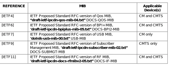
3.1 IPCDN Drafts and Others
Table 1. IPCDN Drafts9,10,11
REFERENCE MIB Applicable Device(s)
[IETF4] IETF Proposed Standard RFC-version of Qos MIB, “draft-ietf-ipcdn-qos-mib-04.txt” DOCS-QOS-MIB
CM and CMTS [IETF6] IETF Proposed Standard RFC-version of BPI+ MIB,
“draft-ietf-ipcdn-bpiplus-mib-05.txt” DOCS-BPI2-MIB
CM and CMTS [IETF7] IETF Proposed Standard RFC-version of USB MIB,
“dolnik-usb-mib-00.txt” USB-MIB
CM only [IETF9] IETF Proposed Standard RFC-version of Subscriber
Management MIB, “draft-ietf-ipcdn-subscriber-mib-02.txt” DOCS-SUBMGT-MIB
CMTS only
[IETF11] IETF Proposed Standard RFC-version of RF MIB, “draft-ietf-ipcdn-docs-rfmibv2-05.txt” DOCS-IF-MIB
CM and CMTS
9
Second row, changed text from “07” to “05”, per ECN OSS-N-03020 (rescinds OSS-N-02229), by GO on 03/21/03.
10
Fifth row, changed text from “04” to “05 per OSS-N-03022 by GO on 03/20/03.
11
3.2 IETF
RFCs
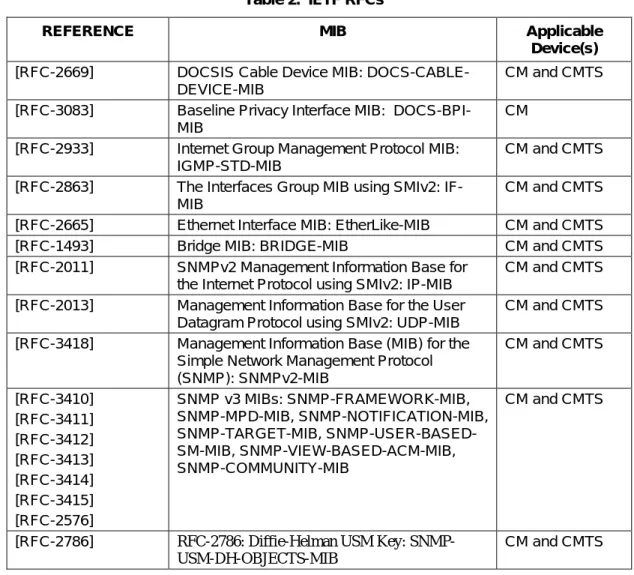
Table 2. IETF RFCs12
REFERENCE MIB Applicable Device(s)
[RFC-2669] DOCSIS Cable Device MIB: DOCS-CABLE-DEVICE-MIB
CM and CMTS [RFC-3083] Baseline Privacy Interface MIB:
DOCS-BPI-MIB
CM [RFC-2933] Internet Group Management Protocol MIB:
IGMP-STD-MIB
CM and CMTS [RFC-2863] The Interfaces Group MIB using SMIv2:
IF-MIB
CM and CMTS [RFC-2665] Ethernet Interface MIB: EtherLike-MIB CM and CMTS [RFC-1493] Bridge MIB: BRIDGE-MIB CM and CMTS [RFC-2011] SNMPv2 Management Information Base for
the Internet Protocol using SMIv2: IP-MIB
CM and CMTS [RFC-2013] Management Information Base for the User
Datagram Protocol using SMIv2: UDP-MIB
CM and CMTS [RFC-3418] Management Information Base (MIB) for the
Simple Network Management Protocol (SNMP): SNMPv2-MIB CM and CMTS [RFC-3410] [RFC-3411] [RFC-3412] [RFC-3413] [RFC-3414] [RFC-3415] [RFC-2576] SNMP v3 MIBs: SNMP-FRAMEWORK-MIB, SNMP-MPD-MIB, SNMP-NOTIFICATION-MIB, SNMP-TARGET-MIB, SNMP-USER-BASED-SM-MIB, SNMP-VIEW-BASED-ACM-MIB, SNMP-COMMUNITY-MIB CM and CMTS
[RFC-2786] RFC-2786: Diffie-Helman USM Key: SNMP-USM-DH-OBJECTS-MIB
CM and CMTS
3.3 Managed Objects Requirements
The following sections detail any additional implementation requirements for the RFCs listed. Reference Appendix A for specific object implementation requirements.
The CM and CMTS MUST support a minimum of 10 available SNMP Table Rows unless otherwise specified by RFC or DOCSIS specification. The CM/CMTS minimum number of available SNMP Table Rows SHOULD mean rows (per table) that are available to support device configuration. CM/CMTS used (default) SNMP Table Row entries MUST NOT apply to the minimum number of available SNMP Table Rows.
3.3.1 CMTS MIB requirements
DOCSIS 1.1 compliant CMTS MUST implement Subscribe Management MIB.
12
3.3.2 Requirements for RFC-2669
RFC-2669 MUST be implemented by DOCSIS 1.1 compliant CMs. DOCSIS 1.1 compliant CMTS MUST implement mandatory required objects (as specified by Appendix A), and SHOULD implement the other non-mandatory required objects.
3.3.3 Requirements for DOCS-IF-MIB
The DOCS-IF-MIB MUST be implemented by DOCSIS 1.1 compliant CMTS and CMs.
The docsIfDownChannelPower object-type MUST be implemented in a CMTS that provides an integrated RF upconverter. If the CMTS relies on an external upconverter, then the CMTS SHOULD implement the docsIfDownChannelPower object-type. The CMTS transmit power reported in the MIB object MUST be within 2 dB of the actual transmit power in dBmV when implemented. IF transmit power management is not implemented, the MIB object will be read-only and report the value of 0 (zero).
The docsIfDownChannelPower object-type MUST be implemented in DOCSIS 1.1 conforming CM's. This object is read-only. When operated at nominal line voltage, at normal room temperature, the reported power MUST be within 3 dB of the actual received channel power. Across the input power range from -15 dBmV to +15 dBmV, for any 1 dB change in input power, the CM MUST report a power change in the same direction that is not less than 0.5 dB. and not more than 1.5 dB.
The access of docsIfDownChannelFrequency object MUST be implemented as RW if a CMTS is in control of the downstream frequency. But if a CMTS provides IF output, docsIfDownChannelFrequency MUST be implemented as read-only and return 0.
All objects added as a result of the DOCS-IF-MIB 13upgrade from RFC2670 to draft-ietf-ipcdn-docs-rfmibv2-05.txt are optional for DOCSIS 1.1 devices, with the exception of objects 'transferred' from the docsIfExt MIB, and objects indicating the CM modulation type. These objects are mandatory for DOCSIS 1.1 devices, and include docsIfDocsisBaseCapability, docsIfCmStatusDocsisOperMode,
docsIfCmStatusModulationType, docsIfCmtsCmStatusDocsisRegMode, and docsIfCmtsCmStatusModulationType. docsIfCmtsChannelUtilizationTable, docsIfCmtsDownChannelCounterTable, and only the first nine MIB objects of
docsIfCmtsUpChannelCounterTable. Refer to Appendix A for details on optional/mandatory status of new DOCS-IF-MIB 14objects.15
“The docsIfQosProfMaxTransmitBurst range MUST be the same as the one defined in the RFIv1.1 specification, section C.1.1.4.6 “Maximum Upstream Channel Transmit Burst Configuration Setting” which has range 0 to 65535.”16
If the CMTS implements the docsIfUpChannelStatus object-type, the CMTS MUST NOT allow it to be set from active(1) directly or indirectly to destroy(6). The CMTS MUST return a wrongValue error. Entries with docsIfUpChannelStatus set to active(1) are logically linked to a physical interface, not temporarily created to clone parameters.17
13
Revised requirement per ECN OSS-N-03066 by GO on 07/10/03.
14
Revised requirement per ECN OSS-N-03066 by GO on 07/10/03.
15
Revised “04” to “05” and added text per OSS-N-03022 by GO on 03/20/03.
16
Added paragraph to Section 3.3.3 per ECN OSS-N-02219, by GO, on 12/02/02.
17
3.3.4 Requirements for RFC-286318
RFC-2863 MUST be implemented by DOCSIS 1.1 compliant CMTS and CMs.
The CMTS/CM ifAdminStatus object MUST provide administrative control over both MAC interfaces and individual channel and MUST be implemented as RW.
The ifType object has been assigned the following enumerated values for each instance of a Data Over Cable Service (DOCS) interface:
CATV MAC interface:: docsCableMacLayer (127)
CATV downstream channel: docsCableDownstream (128) CATV upstream channel:: docsCableUpStream (129) 3.3.4.1 Interface Organization and Numbering
Assigned interface numbers for CATV-MAC and Ethernet (Ethernet-like interface) are used in both the NMAccessTable and IP/LLC filtering table to configure access and traffic policy at these interfaces. These configurations are generally encoded in the configuration file using TLV encoding. To avoid provisioning complexity the interface-numbering scheme MUST comply with the following requirements:
An instance of IfEntry MUST exist for each CATV-MAC interface, downstream channel, upstream channel, and each LAN interface enabled by the CM. The enablements of LAN interfaces MAY be fixed a prior during manufacturing process or MAY be determined dynamically during operation by the CM according to if an interface has a CPE device attached to it or not.19
If the CM has multiple CPE interfaces but only one CPE interface can be enabled at any given time, then the ifTable MUST only contain the entry corresponding to the enabled or the default CPE interface. If a MAC interface consists of more than one upstream and downstream channel, then a separate instance of ifEntry MUST also exist for each channel.
The ifStack group ([RFC-2863]) must be implemented to identify relationship among sub-interfaces. Note that the CATV-MAC interface MUST exist, even though it is broken out into sub-interfaces.
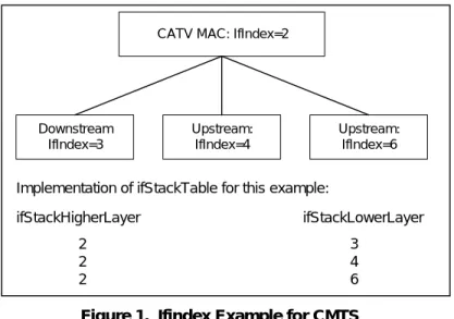
The example below illustrates a MAC interface with one downstream and two upstream channels for a CMTS.
18
RFC # updated to 2863 throughout document per OSS-N-02190 by GO on 11/15/02.
19
Figure 1. Ifindex Example for CMTS
At the CMTS, interface number is at the discretion of the vendor, and SHOULD correspond to the physical arrangement of connections. If table entries exist separately for upstream and downstream channels, then the ifStack group ([RFC-2863]) MUST be implemented to identify the relationship among sub-interfaces. Note that the CATV MAC interface(s) MUST exist, even if further broken out into sub-interfaces.
At the CM, interface MUST be numbered as:
Table 3. CM Interface numbering20
Interfaces Type 1 primary CPE interface
2 CATV-MAC 3 RF-down 4 RF-Up 5 – 15, 32+n Other interfaces
16 - 31 Other interfaces (Reserved)
If CM has more than one CPE interface, then the vendor MUST define which of (n) CPE interfaces is the primary CPE interface. The definition of the primary CPE interface MAY be fixed a prior during
manufacturing process or MAY be determined dynamically during operation by the CM according to which interface has a CPE device attached to it. Regardless how many CPE interfaces the CM has or how the primary CPE interface is defined, the primary interface MUST be interface number 1.
The definition of the secondary CPE interface MAY be fixed a prior during manufacturing process or MAY be determined dynamically during operation by the CM according to which interface has a CPE device attached to it. The secondary CPE, and other interfaces, will start at 5.
DOCSIS CM may have multiple interfaces. If filter(s) (Ip, LLC, or NmAccess) are applied to CM IfIndex 1, the same filter(s) MUST also be applied to the "Other interfaces" (IfIndexes 5 and above); however, filters are never used to limit traffic between the CPE and “Other” interfaces within the CM.21
20
Table 3 updated per ECN OSS-N-02213, chg #1, by GO, on 12/02/02.
21
Replaced sentence per ECN OSS-N-02213, chg #2, by GO, on 12/02/02. CATV MAC: IfIndex=2
Downstream IfIndex=3 Upstream: IfIndex=4 Upstream: IfIndex=6 Implementation of ifStackTable for this example:
ifStackHigherLayer ifStackLowerLayer 2 2 2 3 4 6
3.3.4.2 docsIfCmStatusValue and ifOperStatus Relationship
For CM RF downstream, RF upstream and RF MAC interfaces; the following are the expected relationship of ifOperStatus and docsIfCmStatusValue when ifAdminStatus = up (taken from DOCS-IF-MIB).
Table 4. docsIfCmStatusValue and ifOperStatus Relationship22
IfOperStatus docsIfCmStatusValue
down(2): other(1), notReady(2)
dormant(5): notSynchronized(3), phySynchronized(4), usParametersAcquired(5), rangingComplete(6), ipComplet(7), todEstablished(8),
paramTransferComplete(10), accessDenied(13)
up(1): registrationComplete(11), securityEstablished(9), operational(12) 3.3.4.2.1 ifOperStatus and traffic
If the CM and CMTS interface’s ifAdminStatus= down, the interface MUST not accept or forward any traffic (traffic includes data and MAC management traffic).
3.3.5 Interface MIB and Trap Enable
Interface MIB and Trap Enable specified in RFC-2863 MUST be implemented by DOCSIS 1.1 compliant CMTS and CMs.
If a multi-layer interface model is present in the device, each sub-layer for which there is an entry in the ifTable can generate linkUp/Down traps. Since interface state changes would tend to propagate through the interface stack (from top to bottom, or bottom to top), it is likely that several traps would be generated for each linkUp/Down occurrence. The CM and CMTS MUST implement the ifLinkUpDownTrapEnable object to allow managers to control trap generation, and configure only the interface sub-layers of interest. The default setting of ifLinkUpDownTrapEnable MUST limit the number of traps generated to one, per interface, per linkUp/Down event. Interface state changes, of most interest to network managers, occur at the lowest level of an interface stack.
On CM linkUp/Down event a trap SHOULD be generated by the CM MAC interface and not by any sub-layers of the interface. Therefore, the default setting of ifLinkUpDownTrapEnable for CM MAC MUST be set to enable, and the default setting of ifLinkUpDownTrapEnable for CM RF-Up MUST be set to disable, and the default setting of ifLinkUpDownTrapEnable for CM RF-Down MUST be set to disable.
On CMTS interfaces (MAC, RF-Downstream(s), RF-Upstream(s)) the linkUp/Down event/trap SHOULD be generated by each CMTS interface. Therefore, the default setting of ifLinkUpDownTrapEnable for each CMTS interface (MAC, RF-Downstream(s), RF-Upstream(s)) MUST be set to enable.
3.3.6 Requirements for RFC-2665
RFC-2665 MUST be implemented by DOCSIS 1.1 compliant CMTS and CM if Ethernet or Fast Ethernet interfaces are present.
22
3.3.7 Requirements for RFC-1493
RFC-1493 MUST be implemented by DOCSIS 1.1 compliant CMTS and CMs.
In both the CM and the CMTS (if the CMTS implements transparent bridging), the Bridge MIB ([RFC-1493]) MUST be implemented to manage the bridging process.
In the CMTS that implements transparent bridging, the Bridge MIB MUST be used to represent information about the MAC Forwarder states.
3.3.8 Requirements for RFC-2011
RFC-2011 MUST be implemented by DOCSIS 1.1 compliant CMTS and CMs.
3.3.8.1 The IP Group
The IP group MUST be implemented. It does not apply to IP packets forwarded by the device as a link-layer bridge. For the CM, it applies only to the device as an IP host. At the CMTS, it applies to the device as an IP host, and as a routers if IP routing is implemented.
3.3.8.2 The ICMP Group
The ICMP group MUST be implemented. It does not apply to IP packets forwarded by the device as a link-layer bridge. For the CM, it applies only to the device as an IP host. At the CMTS, it applies to the device as an IP host, and as a routers if IP routing is implemented.
Since CMs do not generate ICMP requests and do not support ICMP Timestamps, Table 24 lists MIB objects that are optional.
3.3.9 Requirements for RFC-2013
RFC-2013 MUST be implemented by DOCSIS 1.1 compliant CMTS and CMs. The UDP group does not apply to IP packets forwarded by the device as a link-layer bridge. For the CM, it applied only to the device an IP host. At the CMTS, it applies to the device only as an IP host.
3.3.10 Requirements for RFC-341823
RFC-3418 MUST be implemented by DOCSIS 1.1 compliant CMTS and CMs.
3.3.10.1 The System Group
The System Group from RFC-3418 MUST be implemented. 24
23
Revised Section 3.3.10 per ECN OSS-N-03066 by GO on 07/10/03.
24
3.3.10.2 The SNMP Group
The SNMP Group from RFC-3418 MUST be implemented. 25
3.3.11 Requirements for DOCS-QOS-MIB26
“draft-ietf-ipcdn-qos-mib-04.txt” MUST be implemented by DOCSIS 1.1 compliant CMTS and CMs
The default values for the MIB objects in docsQosParamSetTable and docsQosServiceClassTable MUST follow the referenced ones in the RFIv1.1 specification. For example,
docsQosParamSetMaxTrafficBurst default value is 3044 (which is 1522 * 2),
docsQosServiceClassMaxTrafficBurst DEFVAL is 3044, docsQosParamSetMaxConcatBurst default value is 1522, and docsQosServiceClassMaxConcatBurst DEFVAL is 1522. If in the future, there are any related default values changed in the RFIv1.1 specification, the related default values in DOCS-QOS-MIB docsQosParamSetTable and docsQosServiceClassTable MUST be changed accordingly even though the MIB file is not changed in time.27
3.3.12 Requirements for “draft-ietf-ipcdn-igmp-mib-01.txt”
“draft-ietf-ipcdn-igmp-mib-01.txt” requirements have been deleted for CMTS and CMs.
3.3.13 Requirements for RFC-2933
RFC-2933 MUST be implemented by DOCSIS 1.1 compliant CMTS and CMs.
Refer to “Appendix J, "Application of RFC-2933 to DOCSIS 1.1 active/passive IGMP devices” for DOCSIS 1.1 IGMP cable device implementation details.
3.3.14 Requirements for DOCS-BPI2-MIB28
“draft-ietf-ipcdn-bpiplus-mib-0705.txt” MUST be implemented by DOCSIS 1.1 compliant CMTS and CM as specified in Appendix A.29
3.3.15 Requirements for USB-MIB30
(Note: Until the USB-MIB becomes an IETF RFC, the draft text will be available on the DOCSIS website.)
25
Revised Section 3.3.10 per ECN OSS-N-03066 by GO on 07/10/03.
26
Revised Section 3.3.11 per ECN OSS-N-03066 by GO on 07/10/03.
27
Added paragraph to the section per ECN OSS-N-02214, by GO on 11/21/02.
28
Revised Section 3.3.14 per ECN OSS-N-03066 by GO on 07/10/03.
29
Changed “07” to “05” per ECN OSS-N-03020 (rescinds OSS-N-02229), by GO on 03/21/03.
30
3.3.16 Requirements for DOCS-SUBMGT-MIB31
“draft-ietf-ipcdn-subscriber-mib-02-.txt”MUST be implemented by DOCSIS 1.1 compliant CMTS.
DOCSIS 1.1 compliant CMTS MUST support a minimum number of filter groups; (30) thirty groups of (20) twenty filters each.
3.3.17 Requirements for RFC-278632
RFC-2786 MUST be implemented by DOCSIS 1.1 compliant CMs. It (RFC-2786) MAY be implemented on the CMTS.
3.3.18 Requirements for RFC-308333
RFC-3083MUST be implemented by DOCSIS 1.1 compliant CMs as specified in Appendix A.
Due to the editorial error in RFC-3083, the DOCSIS 1.1 compliant CM MUST use the following definition for docsBpiCmAuthState and not the definition in RFC-3083.
docsBpiCmAuthState OBJECT-TYPE SYNTAX INTEGER { start(1), authWait(2), authorized(3), reauthWait(4), authRejectWait(5) } MAX-ACCESS read-only STATUS current DESCRIPTION
”The value of this object is the state of the CM authorization FSM. The start state indicates that FSM is in its initial state.”
REFERENCE
”DOCSIS Baseline Privacy Interface Specification, Section 4.1.2.1.” ::= {docsBpiCmBaseEntry 3 }
In addition, compliant CMs MAY create new entries in the docsBpiCmTEKTable for any multicast SID(s) it receives in Auth-Reply messages. If implemented, the multicast SID MUST be used as an index in the docsBpiCmTEKTable in the docsIfCmServiceId field. Note that if the multicast SID is used in the docsBpiCmTEKTable, there MUST NOT be a corresponding entry in the docsIfCmServiceTable for the multicast SID, due to the definition of the docsIfCmService ID in the DOCS-IF-MIB.34
31
Revised Section 3.3.16 per ECN OSS-N-03066 by GO on 07/10/03.
32
Revised Section 3.3.17 per ECN OSS-N-03066 by GO on 07/10/03.
33
Revised Section 3.3.18 per ECN OSS-N-03066 by GO on 07/10/03.
34
3.3.19 Requirement for DOCS-IF-EXT-MIB
A DOCSIS 1.1 compliant CM/CMTS MAY support the DOCS-IF-EXT MIB, which is defined in Appendix K. If a DOCSIS 1.1 CM/CMTS supports the deprecated docsIfExt MIB objects in the docsCableDevice MIB trap definitions, then it MUST also support the DOCS-IF-EXT MIB.
3.3.20 Requirements for DOCS-CABLE-DEVICE-TRAP-MIB
DOCSIS 1.1 compliant CM/CMTS must implement DOCS-CABLE-DEVICE-TRAP-MIB, as specified in Appendix M.
3.3.21 Requirements for SNMPv3 MIBs
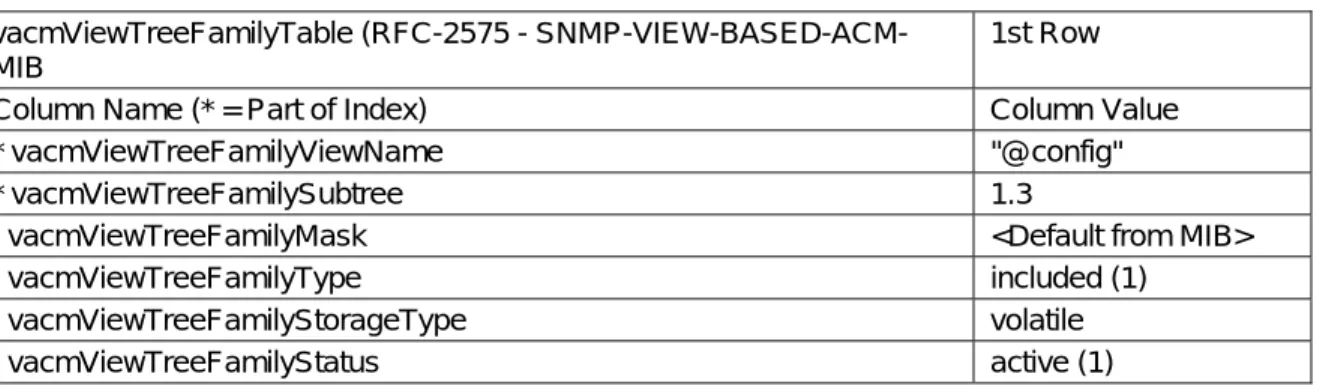
DOCSIS 1.1 compliant CM/CMTS MUST implement the MIBs defined in RFC 3411-3415 and RFC 2576.35 For CMs, the default value for any SNMPv3 object with a storageType textual convention MUST be 'volatile'. This overrides the default value specified in RFC 3413-3415 and RFC 2576. 36
The CM MUST only accept the value of 'volatile' on any SNMPv3 storageType object.
An attempted set to a value of other(1), nonVolatile(3), permanent(4), or readOnly(5) will result an ‘inconsistentValue’ error. Values other than the valid range (1-5) would result a ‘wrongValue’ error. The CM and CMTS SHOULD support a minimum of 30 available rows in the vacmViewTreeFamilyTable object.
3.4 CM Configuration Files, TLV-11 and MIB OIDs/Values
The following sections define the use of CM configuration file TLV-11 elements and the CM rules for translating TLV-11 elements into SNMP PDU (SNMP MIB OID/instance and MIB OID/instance value combinations; also referred to as SNMP varbinds).
This section also defines the CM behaviors, or state transitions, after either pass or fail of the CM configuration process.
For TLV-11 definitions refer to [DOCSIS 5; Appendix C].
3.4.1 CM configuration file TLV-11 element translation (to SNMP PDU)
TLV-11 translation defines the process used by CM to convert CM configuration file information (TLV-11 elements) into SNMP PDU (varbinds). The CM MUST translating CM configuration file TLV-11 elements into a single SNMP PDU containing (n) MIB OID/instance and value components (SNMP varbinds). Once a single SNMP PDU is constructed, the CM will process the SNMP PDU and determine CM configuration pass/fail based on the rules for CM configuration file processing, described below. However, if a CM is not physically capable of processing a, potentially large, single CM configuration file generated SNMP PDU,
35
Revised RFC references per ECN OSS-N-03066 by GO on 07/10/03.
36
then the CM must still behave as if all MIB OID/instance and value components (SNMP varbinds), from CM configuration file TLV-11 elements, are processed as a single SNMP PDU.
In accordance with [RFC-341637], the single CM configuration file generated SNMP PDU will be treated “as if simultaneous” and the CM must behave consistently, regardless of the order in which TLV-11 elements appear in the CM configuration file, or SNMP PDU. The singular CM configuration file generated SNMP PDU requirement is consistent with SNMP PDU packet behaviors, received from an SNMP manager; SNMP PDU varbind order does not matter, and there is no defined MAX SNMP PDU limit.
The CM configuration file MUST NOT contain duplicate TLV-11 elements (duplicate means SNMP MIB object has either identical OID or OID from the old and new MIB that actually point to the same SNMP MIB object). If duplicate TLV-11 elements are received by the CM, from the CM configuration file, then the CM MUST fail CM configuration.
3.4.1.1 Rules for CreateAndGo and CreateAndWait
The CM MUST support CreateAndGo for row creation.
The CM MAY support CreateAndWait; with the constraint that CM configuration file TLV-11 elements MUST NOT be duplicated (all SNMP MIB OID/instance must be unique). For instance, an SNMP PDU, constructed from CM configuration file TLV-11 elements, which contains an SNMP CreateAndWait value, for a given SNMP MIB OID/instance, MUST NOT also contain an SNMP Active value for the same SNMP MIB OID/instance (and vice versa). A CM configuration file MAY contain a TLV-11 CreateAndWait element if the intended result is to create an SNMP table row which will remain in the SNMP NotReady or SNMP NotInService state until a non-configuration file SNMP PDU is issued, from an SNMP manager, to update the SNMP table row status.
Both SNMP NotReady and SNMP NotInService states are valid table row states after an SNMP CreateAndWait instruction.
3.4.2 Ignore CM configuration TLV-11 elements which are not supported by CM
If any CM configuration file TLV-11 elements translate to SNMP MIB OIDs that are not MIB OID elements supported by the CM, then those SNMP varbinds MUST be ignored, and treated as if they had not been present, for the purpose of CM configuration. This means that the CM will ignore SNMP MIB OIDs for other vendor's private MIBs as well as standard MIB elements that the CM does not support.
CMs that do not support SNMP CreateAndWait for a given SNMP MIB table MUST ignore, and treated as if not present, the set of columns associated with the SNMP table row.
If any CM configuration file TLV-11 element(s) are ignored, then the CM MUST report via the CM
configured notification mechanism(s), after the CM is registered. The CM notification method MUST be in accordance with the “Standard DOCSIS event” section, defined within this document.
3.4.3 CM state after CM configuration file processing success
After successful CM configuration, via CM configuration file, CM MUST proceed to register, with CMTS, and pass data.
37
3.4.4 CM state after CM configuration file processing failure
If any CM configuration file generated SNMP PDU varbind performs an illegal set operation (illegal, bad, or inconsistent value) to any MIB OID/instance supported by the CM, then processing of the CM configuration file MUST fail. Any CM configuration file generated SNMP PDU varbind set failure MUST cause a CM configuration failure, and the CM MUST NOT proceed with CM registration.
3.5 Treatment
and
Interpretation of MIB Counters on the CM
Octet and packet counters implemented as counter32 and counter64 MIB objects are defined to be monotonically increasing positive integers with no specific initial value and a maximum value based on the counter size that will roll-over to zero when it is exceeded. In particular, counters are defined such that the only meaningful value is the difference between counter values as seen over a sequence of counter polls. However there are two situations that can cause this consistent monotonically increasing behavior to change: 1) resetting the counter due to a system or interface reinitialization or 2) a rollover of the counter when it reaches its maximum value of 2**32-1 or 2**64-1. In these situations, it must be clear what the expected behavior of the counters should be.
Case 1: Whenever the state of an interface changes resulting in an “interface counter discontinuity” as defined in RFC-2863. In this case the value of the ifXTable.ifXEntry.ifCounterDiscontinuityTime for the affected interface MUST be set to the current value of sysUpTime and ALL counters for the affected interface MUST be set to ZERO. Setting the ifAdminStatus of specified interface to down(2) MUST NOT be considered as an interface reset.
Case 2: SNMP Agent Reset. In this case, the value of the sysUpTime MUST be set to ZERO, all interface ifCounterDiscontinuityTime values MUST be set to ZERO, and all interface counters MUST be set to ZERO. Also, all other counters being maintained by the SNMP Agent MUST be set to ZERO. Case 3: Counter Rollover. When a counter32 object reaches its maximum value of 4,294,967,295 the next value MUST be ZERO. When a counter64 object reaches its maximum value of
18,446,744,073,709,551,615 the next value MUST be ZERO. Note that unless a CM or CMTS vendor provides a means outside of SNMP to preset a counter64 or counter32 object to an arbitrary value, it will not be possible to test any rollover scenarios for counter64 objects (and many counter32 objects as well). This is because it is not possible for these counters to rollover during the service life of the device (see discussion in RFC-2863 section 3.1.6).
3.6 Config File Element – SNMP V3Notification Receiver
38The following sections detail the CM Configuration File TLV-38 “DOCSIS V3 Notification Receiver” mapping into SNMP V3 functional tables. A CM MUST support a minimum of 10 TLV-38 elements in a configuration file. For TLV-38 definitions refer to [DOCSIS 5; Appendix C].
Upon receiving one TLV 38, the CM MUST make entries to the following tables in order to cause the desired trap transmission: snmpNotifyTable, snmpTargetAddrTable, snmpTargetAddrExtTable, snmpTargetParamsTable, snmpNotifyFilterProfileTable, snmpNotifyFilterTable, nmpCommunityTable, usmUserTable, vacmSecurityToGroupTable, vacmAccessTable, and vacmViewTreeFamilyTable A config file MAY also contain TLV MIB elements that make entries to any of the 10 tables listed above. These TLV MIB elements MUST NOT use index columns that start with the characters "@config".
38
3.6.1 Mapping of TLV fields into created SNMP V3 Table rows
The tables in this section show how the fields from the Config file TLV element (the tags in angle brackets <> ) are placed into the SNMP V3 tables.
The correspondence between TLV fields and table tags <TAG> is shown below: <IP Address> TLV 38.1 <Port> - TLV 38.2 <Trap type> TLV 38.3 <Timeout> TLV 38.4 <Retries> TLV 38.5 <Filter OID> TLV 38.6 <Security Name> TLV 38.7
These tables are shown in the order that the agent will search down through them when a notification is generated in order to determine who to send the notification to and how to fill out the contents of the notification packet.
3.6.1.1 snmpNotifyTable
Create 2 rows with fixed values, if 1 or more TLV elements are present Table 5. snmpNotifyTable snmpNotifyTable (RFC-2573 -
SNMP-NOTIFICATION-MIB
1st Row 2nd Row Column Name (* = Part of Index) Column Value Column Value
* snmpNotifyName "@config_inform" "@config_trap" snmpNotifyTag "@config_inform" "@config_ trap "
snmpNotifyType inform (2) trap (1) snmpNotifyStorageType volatile volatile snmpNotifyRowStatus Active (1) Active (1)
3.6.1.2 snmpTargetAddrTable
Create 1 row for each TLV element in the config file
Table 6. snmpTargetAddrTable snmpTargetAddrTable (RFC-2573 -
SNMP-TARGET-MIB
New Row Column Name (* = Part of Index) Column Value
* snmpTargetAddrName "@config_n" Where n ranges from 0 to m-1 where m is the number of notification receiver TLV elements in the config file
snmpTargetAddrTDomain snmpUDPDomain = snmpDomains.1 snmpTargetAddrTAddress
(IP Address and UDP Port of the Notification Receiver)
OCTET STRING (6) Octets 1-4: <IP Address> Octets 5-6: <Port> snmpTargetAddrTimeout <Timeout> from the TLV snmpTargetAddrRetryCount <Retries> from the TLV snmpTargetAddrTagList If <Trap type> == 1, 2 or 4
"@config_trap"
Else If <Trap type> = 3 or 5 "@config_inform"
snmpTargetAddrParams "@config_n" (Same as snmpTargetAddrName value) snmpTargetAddrStorageType volatile
snmpTargetAddrRowStatus active (1) 3.6.1.3 snmpTargetAddrExtTable
Create 1 row for each TLV element in the config file
Table 7. snmpTargetAddrExtTable snmpTargetAddrExtTable(RFC-2576 -
SNMP-COMMUNITY-MIB)
New Row Column Name (* = Part of Index) Column Value
* snmpTargetAddrName "@config_n" Where n ranges from 0 to m-1 where m is the number of notification receiver TLV elements in the config file
snmpTargetAddrTMask <Zero length octet string> snmpTargetAddrMMS 0
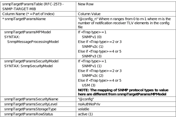
3.6.1.4 snmpTargetParamsTable
Create 1 row for each TLV element in the config file. If <Trap type> is 1, 2, or 3, or if the <Security Name> Field is zero-length, create the table as follows:
Table 8. snmpTargetParamsTable for <Trap type> 1, 2, or 3 snmpTargetParamsTable(RFC-2573 -
SNMP-TARGET-MIB
New Row Column Name (* = Part of Index) Column Value
* snmpTargetParamsName "@config_n" Where n ranges from 0 to m-1 where m is the number of notification receiver TLV elements in the config file snmpTargetParamsMPModel SYNTAX: SnmpMessageProcessingModel If <Trap type> = 1 SNMPv1 (0)
Else If <Trap type> = 2 or 3 SNMPv2c (1)
Else if <Trap type> = 4 or 5 SNMPv3 (3)
snmpTargetParamsSecurityModel SYNTAX: SnmpSecurityModel
If <Trap type> = 1 SNMPv1 (1)
Else If <Trap type> = 2 or 3 SNMPv2c (2)
Else if <Trap type> = 4 or 5 USM (3)
NOTE: The mapping of SNMP protocol types to value here are different from snmpTargetParamsMPModel snmpTargetParamsSecurityName "@config"
snmpTargetParamsSecurityLevel noAuthNoPriv snmpTargetParamsStorageType volatile snmpTargetParamsRowStatus active (1)
Table 9. snmp TargetParamsTable for ,Trap type> 4 or 5 snmpTargetParamsTable(RFC-2573 -
SNMP-TARGET-MIB
New Row Column Name (* = Part of Index) Column Value
* snmpTargetParamsName "@config_n" Where n ranges from 0 to m-1 where m is the number of notification receiver TLV elements in the config file snmpTargetParamsMPModel SYNTAX: SnmpMessageProcessingModel If <Trap type> = 1 SNMPv1 (0)
Else If <Trap type> = 2 or 3 SNMPv2c (1)
Else if <Trap type> = 4 or 5 SNMPv3 (3)
snmpTargetParamsSecurityModel SYNTAX: SnmpSecurityModel
If <Trap type> = 1 SNMPv1 (1)
Else If <Trap type> = 2 or 3 SNMPv2c (2)
Else if <Trap type> = 4 or 5 USM (3)
NOTE: The mapping of SNMP protocol types to value here are different from snmpTargetParamsMPModel snmpTargetParamsSecurityName <Security Name>
snmpTargetParamsSecurityLevel The security level of <Security Name> snmpTargetParamsStorageType volatile
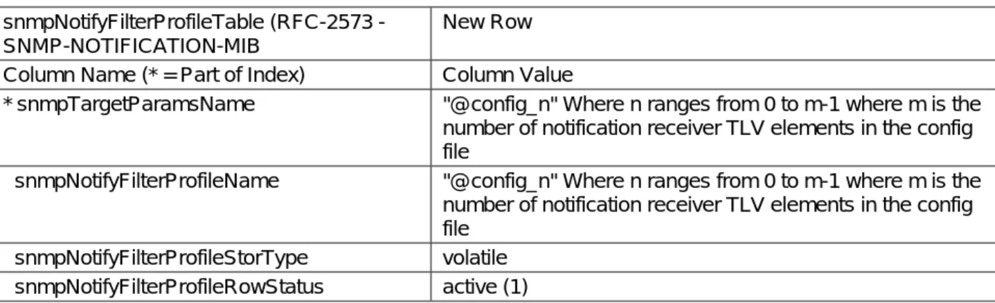
snmpTargetParamsRowStatus active (1) 3.6.1.5 snmpNotifyFilterProfileTable –
Create 1 row for each TLV that has a non-zero <Filter Length>
Table 10. snmpNotifyFilterProfileTable snmpNotifyFilterProfileTable(RFC-2573 -
SNMP-NOTIFICATION-MIB
New Row Column Name (* = Part of Index) Column Value
* snmpTargetParamsName "@config_n" Where n ranges from 0 to m-1 where m is the number of notification receiver TLV elements in the config file
snmpNotifyFilterProfileName "@config_n" Where n ranges from 0 to m-1 where m is the number of notification receiver TLV elements in the config file
snmpNotifyFilterProfileStorType volatile snmpNotifyFilterProfileRowStatus active (1)
3.6.1.6 snmpNotifyFilterTable
Create 1 row for each TLV that has a non-zero <Filter Length>
Table 11. snmpNotifyFilterTable snmpNotifyFilterTable(RFC-2573 -
SNMP-NOTIFICATION-MIB
New Row Column Name (* = Part of Index) Column Value
* snmpNotifyFilterProfileName "@config_n" Where n ranges from 0 to m-1 where m is the number of notification receiver TLV elements in the config file
* snmpNotifyFilterSubtree <Filter OID> from the TLV snmpNotifyFilterMask <Zero Length Octet String> snmpNotifyFilterType included (1)
snmpNotifyFilterStorageType volatile snmpNotifyFilterRowStatus active (1) 3.6.1.7 snmpCommunityTable
Create 1 row with fixed values if 1 or more TLVs is present
This causes SNMPV1 and V2c Notifications to contain the community string in snmpCommunityName Table 12. snmpCommunityTable
snmpCommunityTable (RFC-2576 - SNMP-COMMUNITY-MIB
1st Row Column Name (* = Part of Index) Column Value * snmpCommunityIndex "@config" snmpCommunityName "public" snmpCommunitySecurityName "@config"
snmpCommunityContextEngineID <The engineID of the cable modem> snmpCommunityContextName <Zero length octet string>
snmpCommunityTransportTag <Zero length octet string> snmpCommunityStorageType volatile
snmpCommunityStatus active (1) 3.6.1.8 usmUserTable
Create 1 row with fixed values, if 1 or more TLVs is present. Other rows are created, one each time the engine ID of a trap receiver is discovered
This specifies the user name on the remote notification receivers to send notifications to.
One row in the usmUserTable is created. Then when the engine ID of each notification receiver is discovered, the agent copies this row into a new row and replaces the 0x00 in the usmUserEngineID column with the newly discovered value.