C
ONTENTS
Preface... 6
Using This Guide ...6
Topic Navigation ...7
Text Conventions ...8
Deskset and Cordless Handset Menu Navigation...9
Additional Documentation ...9
Installation ...10
System Overview ...11
Software Version Compatibility ...13
System Installation Overview ...14
Recommended Installation Sequence...17
Planning Your System and Network Configuration...19
About Modes of Operation ...19
IP Addresses and Connectivity ...20
Extension Assignments...21
Analog Telephones (ATA)...21
Site Preparation...22
Network Requirements...22
Placement Considerations ...23
Power Considerations ...23
Other Preparations ...24
Assigning Telephone Lines and Extensions...25
Providing Limited Telephone Service During AC Power Outages...25
Analog Line Connection Order on PSTN Gateways...25
Wall Mounting...28
Grounding...29
Gateway Installation ...31
Deskset Installation ...35
SB67050 ATA Installation...42
Connecting Analog Devices to the ATA...43
SB67040 Cordless Handset Installation...49
Charger Installation...49
Battery Installation ...50
Battery Charging...51
TL7600 Cordless Headset Installation ...52
Charger Installation...52 Battery Installation ...53 Battery Charging...54
Getting Started ...55
PSTN Gateway Features...56 T1 Gateway Features...58Gateway Front Panel Interface...60
Gateway Configuration...62
Upgrade Gateway Software ...63
ATA Features...65
ATA Front Panel Interface...67
ATA Configuration...68
Upgrade ATA Software ...69
Resetting Devices ...71
Deskset IP Settings...73
Set/Edit Static IP ...75
IP Status...76
System Configuration ...79
The Web User Interface (WebUI)...80
WebUI Overview...81
Log in as Administrator...82
Error Handling ...84
System Settings...85
Setting Line Appearance Mode ...86
Dial Plan Settings ...87
Direct Inward Dial (T1 Gateway)...91
Trunk Naming ...97
Trunk Reservation (Outgoing Calls) ...98
PSTN Gateway Trunk Routing (Incoming Calls) ... 100
T1 Settings ... 101
T1 Diagnostics... 105
ATA Settings... 106
ATA FXS Ports ... 107
Fax Overview ... 109
Overhead Paging Overview... 112
Paging Zones... 121
Updating Devices... 124
Product Registration ... 129
Troubleshooting...130
Common Troubleshooting Procedures ... 131
Resetting Devices... 131
Resolving General Functional Issues... 133
Resolving PSTN Gateway Audio Echoes ... 136
Resolving General Audio Issues... 138
Initial Installation ... 146 Display Messages... 147 T1 Gateway Indicators ... 151 PSTN Gateway Setup... 153 WebUI... 154 Administrator WebUI ... 154 User WebUI... 161 PC/Deskset Interaction ... 162
Other Deskset Features... 163
SB67050 Analog Terminal Adapter... 167
General Troubleshooting ... 167
Music on Hold (MoH)... 169
Overhead Paging (OHP) ... 172
Fax Configuration ... 183
Analog Phone... 187
Group Mailbox... 189
Appendixes ...190
Appendix A: Technical Specifications ... 190
Appendix B: Default Settings... 193
Appendix C: Part Lists ... 197
SB67010 PSTN Gateway Parts List ... 197
SB67060 T1 Gateway Parts List ... 198
SB67020 Deskset Parts List... 199
SB67030 Deskset Parts List... 200
SB67050 Analog Terminal Adapter (ATA) Parts List ... 201
SB67040 Cordless Handset Parts List ... 202
Appendix D: Maintenance... 204
Appendix E: Important Safety Instructions ... 205
Appendix F: Limited Warranty... 207
P
REFACE
This Installation Guide provides instructions for installing and setting up your Synapse system with software version 1.9.2or later. See page 13 for instructions on checking the software version on the Gateway, the Deskset, and the ATA.Before using this AT&T product, please read “Appendix E: Important Safety Instructions” on page 205. Please read this guide thoroughly for all the information necessary to install your new AT&T product.
Using This Guide
The following sections provide instructions for using this guide: “Topic Navigation” on page 7
“Text Conventions” on page 8
“Deskset and Cordless Handset Menu Navigation” on page 9.
For customer service or product information, contact the person who installed your system. If your installer is unavailable, visit our web site at www.telephones.att.com/smb or call
1 (888) 916-2007
. In Canada, dial1 (888) 883-2474
.Some illustrations in this document contain very small text that is not intended to be read. Sometimes the image is present just to help you find the correct screen; in others, full size text conveys the intended information.
Topic Navigation
This guide allows easy navigation between topics and the ability to return to your original topic. Figure 1 illustrates the navigation conventions within the guide.
Synapse Installation Guide
Preface 6
PREFACE
This Installation Guide provides instructions for installing and setting up your Synapse system with software version 1.9.2or later. See page 13 for instructions on checking the software version on the Gateway, the Deskset, and the ATA.Before using this AT&T product, please read Appendix E: Important Safety Instructions on page 205. Please read this guide thoroughly for all the information necessary to install your new AT&T product.
Using This Guide
The following sections provide instructions for using this guide:
Topic Navigation on page 7
Text Conventions on page 8
Deskset and Cordless Handset Menu Navigation on page 9.
For customer service or product information, contact the person who installed your system. If your installer is unavailable, visit our web site at www.telephones.att.com/smb or call 1 (888) 916-2007. In Canada, dial1 (888) 883-2474.
Some illustrations in this document contain very small text that is not intended to be read. Sometimes the image is present just to help you find the correct screen; in others, full size text conveys the intended information.
Task Link
Click on this link to move to the beginning of the instructions for this task.
Back to Table of Contents
Click on the page heading to move to the Table of Contents.
Previous and Next Page Back to Last Page Viewed
Text Conventions
Table 1 lists text formats and their uses.
Table 1. Description of Text Conventions
Text Format Description
Screen Identifies text that appears on the screen in a title, menu, or
prompt.
HARD KEY or DIAL-PAD KEY Identifies a hard key, including the dial-pad keys.
Identifies a soft key.
Figure 1, Table 1 Identifies a figure or table.
“Topic Navigation” on page 7 Identifies a hyperlink to another part of this document or, if it begins with ”www”, an Internet web site. You need Internet access to view web sites.
[PSTN], [T1], [ATA], [Handset], [Headset] Identifies information predominately about devices and capabilities beyond the basic configuration of a Gateway and Desksets. See “System Overview” on page 11.
Example of a Note.
Example of a Caution. Notes give more information, usually in a
procedure.
A caution means that loss of data or unintended circumstances may result.
Deskset and Cordless Handset Menu Navigation
To access items in the menus, you can either use theNavigation key to highlight the function and press SELECT or press a numeric key on the dial pad. The procedures in this guide use the numeric keypad entry as the preferred method for selecting a function.
Additional Documentation
Downloadable copies of all Synapse documents, including user’s and administrator’s guides, installation instructions and quick-start guides, are available at
www.telephones.att.com/synapseguides
.C
H A P T E R
1
I
NSTALLATION
This section describes the physical installation of the Synapse devices. Each system must include at least one PSTN Gateway or one T1 Gateway. Each PSTN Gateway supports up to four analog telephone lines. Up to four PSTN Gateways can support up to 16 analog telephone lines. The T1 Gateway supports up to 23 T1 PRI voice channels.
“System Overview” on page 11
“Planning Your System and Network Configuration” on page 19 “Recommended Installation Sequence” on page 17
“Site Preparation” on page 22
“Assigning Telephone Lines and Extensions” on page 25 “Gateway and ATA Placement” on page 27
“Gateway Installation” on page 31 “Deskset Installation” on page 35 “SB67050 ATA Installation” on page 42
“SB67040 Cordless Handset Installation” on page 49 “TL7600 Cordless Headset Installation” on page 52.
You can view Synapse installation videos at
www.telephones.att.com/smb
. In the left navigation menu, click on Product Support and then Video Gallery.System Overview
1. AT&T SB67010 PSTN Gateway — Each PSTN Gateway provides access to up to four
analog outside telephone lines. The system can have up to four PSTN Gateways, supporting up to 16 telephone lines. Information that is only about the PSTN Gateway is designated by [PSTN] in this guide.
2. AT&T SB67060 T1 Gateway — The T1 Gateway supports the T1 PRI (Primary Rate Interface) that provides access to up to 23 voice channels to support up to 23
simultaneous calls. The system can have only one T1 Gateway. Information that is only about the T1 Gateway is designated by [T1] in this guide.
3. AT&T SB67020 Deskset — A Deskset with a standard screen and Programmable Feature Keys. The system can have up to 100 Desksets, and you can combine SB67020 and SB67030 Desksets. Information that is only about the SB67020 Deskset is designated by [020] in this guide.
4. AT&T SB67030 Deskset — A Deskset with a large screen and a DECT 6.0 radio to host the optional Cordless Handset and Headset accessories. The system can have up to 100 Desksets, and you can combine SB67030 and SB67020 Desksets. Information that is only about the SB67030 Deskset is designated by [030] in this guide.
5. AT&T SB67040 Cordless Accessory Handset (Optional, requires SB67030 Deskset) — The Cordless Handset duplicates many of the Deskset features and provides a high degree of mobility. Information that is only about the Cordless Handset is designated by [Handset] in this guide.
6. AT&T TL7600 Cordless Accessory Headset (Optional, requires SB67030 Deskset) — The Headset lets you work while you talk. Information that is only about the Cordless Headset is designated by [Headset] in this guide.
1
3
5 6
2
7. AT&T SB67050 Analog Terminal Adapter (ATA - Optional)— The ATA allows the integration of non-Synapse devices, such as analog telephones, a fax machine, overhead paging equipment, and a music-on-hold source into the Synapse system. It also provides Group Mailboxes to allow different people to access the same Mailbox. The system can have only one ATA. Information that is only about the ATA is designated by [ATA] in this guide.
8. Web User Interface (WebUI) — The WebUI provides the ability to customize your system for your business from a PC that is on the same Local Area Network. The WebUI resides on the Gateways, ATA, and Desksets, and is updated with device software updates. See “Updating Devices” on page 124.
You can register only one AT&T SB67040 Cordless Handset and only one AT&T TL7600 Cordless Headset to a SB67030 Deskset. Up to five SB67030 Desksets can have cordless accessories, although this number can increase depending on your office environment. Factors such as proximity of Desksets, number of simultaneous calls, and structural obstacles affect how many Desksets can have cordless accessories. When a Deskset has cordless accessories, they are all part of the same extension, and only one extension device can be used at a time.
To integrate the Headset into the system, see “User Settings” in the SB67030 Deskset and Accessories User’s Guide at www.telephones.att.com/synapseguides, rather than the manual that is packaged with the Headset.
8 7
Software Version Compatibility
Systems with software versions 1.9.1 and later support the features described in this guide. All Gateways, ATAs and Desksets must have compatible software versions installed.
To determine the software version of Gateways and the ATA from the device front panel, from idle, press SELECT, SELECT, and then DOWN. The software version appears, as shown in Figure 3.
To determine the SB67020 Deskset software version, press MENU, then 4, and then the Navigation key to display the software version as shown in Figure 4.
To determine the SB67030 Deskset software version, press MENU, then 4. See the P Firmware version as shown in Figure 5.
To determine the software version of all installed devices, log in as administrator. See
“Log in as Administrator” on page 82. Then click to see the software versions and other information, as shown in Figure 2. There may be a delay as the system gathers this information.
Figure 3. Gateway Software Version
Figure 4. SB67020 Deskset Software Version
Figure 5. SB67030 Deskset Software Version
6:9HUY ):9HU= 'HYLFH,QIR
System Installation Overview
Figure 6 illustrates how the Synapse system differs from conventional telephone systems in that calls are not coordinated by a central controller. Instead, the system uses a distributed control system over a new or existing LAN.
If you install one SB67010 PSTN Gateway or SB67060 T1 Gateway and then one Deskset, the feedback described in this guide matches what you see on your system devices.
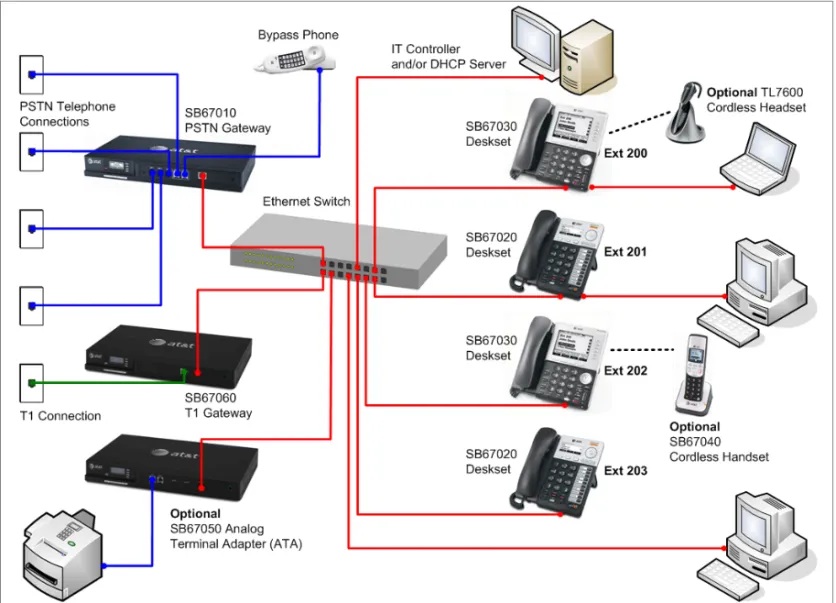
A system must have at least one PSTN Gateway or one T1 Gateway. There can be up to four PSTN Gateways, and a system can include both a T1 Gateway and PSTN Gateways. Figure 7 illustrates the minimum components needed to make the system work (blue line = telephone; red lines = Ethernet).
Figure 7. Simplified System (PSTN Gateway and SB67030 Deskset Shown)
The system uses a Local Area Network (LAN) for system communication. It uses Public Switched Telephone Network (PSTN) connections for outside calls.
System Installation Overview with Optional Analog Terminal Adapter
If you have analog devices that you want to attach to the system, you will need an AT&T SB67050 Analog Terminal Adapter (ATA). The Synapse system supports one ATA per system. The ATA allows you to attach hardware such as conference phones, overhead paging equipment, a fax machine, or a source for Music On Hold (MoH) to Synapse. Figure 8 illustrates a more complex installation (blue lines = telephone; red lines = Ethernet; orange lines = audio), but there are different options for attaching some of the equipment to the ATA.
Install the ATA after you have installed at least one Gateway and the Desksets.
Deskset Local Area Network (LAN) Gateway PSTN Plug
Music on Hold Source
Fax Machine ATA
Analog Telephone/ Conference Phone Overhead Paging System
Recommended Installation Sequence
1. Prepare your site for installation. See “Site Preparation” on page 22.
2. Install the PSTN and/or T1 Gateways. See “Gateway Installation” on page 31.
3. If you have only one Gateway, install the first Deskset. See “Deskset Installation” on page 35. This Deskset is assigned extension number 200 with no Direct Inward Dialing.
4. If necessary, change the mode of operation from Call Appearance mode to Line Appearance mode. See “About Modes of Operation” on page 19.
5. Configure the Dial Plan Settings and [T1] Direct Inward Dialing (DID). Unless you do this, the other Desksets will be assigned sequential three-digit extension numbers starting with 201 and without DID numbers.
To use DID, see “Dial Plan Settings” on page 87 and “Direct Inward Dial (T1 Gateway)” on page 91.
Use the WebUI to change the Dial Plan Settings if you want the first extension digit to be something other than 2, possibly to correspond to the DID numbers, or if you want the parked-call extension numbers to start with a digit other than 1. After changing the Number of Digits and Default Phone Extension Prefix, manually change the extension number of the first Deskset you installed, and manually set its DID number.
Changing the number of extension digits after installing some Desksets may result in undesired extension number re-assignment, where the last three digits of previous extension numbers may not be preserved.
6. Install the other Desksets. See “Deskset Installation” on page 35.
7. Optional: Install the AT&T SB67050 Analog Terminal Adapter (ATA). See “SB67050 ATA Installation” on page 42. If you install You cannot enable Line Appearance mode if a T1 Gateway is installed in your system. Line Appearance mode is not compatible with the T1 Gateway and T1 Gateway features such as DID.
8. Continue configuring the system using the WebUI. See “System Configuration” on page 79. 9. Complete post-installation tasks.
If you have set the system to use Call Appearance mode, ask all users to record their user names on their Desksets. See “Name Recording for the Auto Attendant Directory” in the Synapse Administrator’s Guide at
www.telephones.att.com/synapseguides.
If you have set the system to use Call Appearance mode, distribute and register any Cordless Handsets or Headsets. Synapse Cordless Handsets are not compatible with Line Appearance mode. See “SB67040 Cordless Handset Installation” on page 49 and “TL7600 Cordless Headset Installation” on page 52.
Planning Your System and Network Configuration
This section describes several important configuration options that you should be aware of before you install the Synapse system. These options include Operation Mode (Call Appearance versus Line Appearance), IP addresses and connectivity, extension number assignments, analog bypass lines and analog telephones in the Synapse system.
About Modes of Operation
The system administrator can configure the Synapse system to operate in one of two different modes: Call Appearance mode and Line Appearance mode. The operation mode affects how Deskset users make, answer, and manage calls. Each mode provides a unique set of configurable features.
Before beginning the installation, you and the system administrator should decide which mode will work best for the site.
Call Appearance Mode
In Call Appearance mode, each Deskset has virtual “lines” (5 on SB67030 Desksets, and up to 10 on SB67020 Desksets) for calls to and from external numbers (232-555-0176, for example) or other extensions (Extension 220, for example). These virtual lines are called Call Appearances.
Systems using Call Appearance mode can have any combination of PSTN Gateways, T1 Gateway, and an optional ATA. In Call Appearance mode, SB67030 Desksets can have SB67040 Cordless Handsets and TL7600 Cordless Headsets.
Line Appearance Mode
In Line Appearance mode, each line that Deskset users can access corresponds to an actual physical line connected to the PSTN Gateway (the Synapse system can have up to four PSTN Gateways providing up to 16 lines). Incoming lines are mapped to Programmable Feature Keys on Desksets. You can assign different lines to different Desksets or groups of Desksets. You can configure SB67020 Desksets to access up to 9 lines and SB67030 Desksets to access up to 4 lines.
Other Desksets in the system can share these lines and display the line status. Incoming calls on a line ring at all Desksets that share that line. Users at Desksets that share lines can see when lines are ringing, busy, or on hold.
Systems using Line Appearance mode must use PSTN Gateways only. An optional ATA is also compatible with Line Appearance mode. For more information, see “ATA Fax Line Configuration” on page 26. A system using Line Appearance mode cannot support the T1 Gateway, Ring Groups, Call Queue and some Deskset-specific features. For more information, see the Synapse
Administrator’s Guide.
In Line Appearance mode, SB67030 Desksets cannot use SB67040 Cordless Handsets, although TL7600 Cordless Headsets are compatible with Line Appearance mode.
IP Addresses and Connectivity
An IP address is an individual numeric identification assigned to devices on a computer network. At least one Synapse device needs a network-assigned IP address on the subnet shared with any computers that will allow access to the WebUI. Valid IP addresses on the same subnet allow devices on the network to identify each other and enable communication.
This IP address may be assigned from a Dynamic Host Configuration Protocol (DHCP) server, or set statically to the same subnet, and will be separate from the self-assigned 169.254.xxx.xxx link-local address that the Synapse devices use to communicate with each other. When setting up the IP address on a Synapse device, this network IP address used for WebUI connectivity is the only address you can change.
The network IP addresses can be assigned in two ways:
1. The Synapse device can request a network server to automatically assign an IP address. This IP address is a dynamic assignment; the address is on lease from the server. The lease is renewed as long as the device remains connected and there is no change to the network. However, if the device is disconnected, or if there is a network or AC power interruption, the lease may not be renewed (that is, the IP address expires) and a new IP address may be assigned.
Most LANs use servers to automatically assign IP addresses. Synapse defaults to assuming that this automatic assignment will occur.
Some servers have default settings that limit the number of network IP addresses assigned to devices on the network. You should log in to your server to confirm that the IP range is sufficient to accommodate at least one of the Synapse devices that you are adding as at least one Synapse device needs an assigned IP address to enable WebUI
2. The Synapse Administrator can manually assign a static system IP address. This IP address does not change, even when there are network or AC power interruptions. Some installations will require manual static IP assignment.
A switched-network topology is recommended. This topology refers to the network virtual shape or structure and does not necessarily reflect the physical layout. Switched networks involve connecting the network components to switches rather than hubs; this improves network communication.
Extension Assignments
The system assigns the first Deskset to join the network as extension 200. At this point you can use the WebUI to set a different first digit for extension numbers for Desksets that will be connected to the network. If desired, you should also change the number of digits from three to four at this point. See “Dial Plan Settings” on page 87.
The system automatically assigns each additional Deskset an extension number in ascending order as it is connected to the LAN. Once the Desksets are connected to the same network, they find each other through Peer-to-Peer (P2P) discovery protocols and automatically self-configure. Additional telephony and network configuration is administered through the WebUI.
Even if you unplug a unit, its extension number is reserved. If you want to remove an extension from the network, you must delete the extension number using the WebUI Device Management menu. Deletion ensures that the Deskset does not tie up an extension. You can use the WebUI to change or delete extension numbers. For more information, see the Synapse Administrator’s Guide.
Analog Telephones (ATA)
The FXS ports can provide plain old telephone service (POTS) support for up to two analog phones. These are commonly speakerphones and legacy telephones. One of these ports can also be used to connect a fax machine or some models of Overhead Paging equipment. When you connect analog telephones, they can be assigned using the WebUI to some telephone features, such as Ring Group, Auto Attendant menus, and Call Forward–No Answer targets.
Site Preparation
This section describes how to prepare your site for a successful Synapse system installation.
Network Requirements
For more information on the network configuration, see“Planning Your System and Network Configuration” on page 19. A switched network topology is recommended for your LAN (using standard 10/100 Ethernet switches that carry traffic
at a nominal rate of 100 Mbit/s).
The office LAN infrastructure should use Cat.-5 (or better) cable.
The LAN connections to Synapse devices should all be wired. However, wireless connections to other devices (such as laptops) in your office network that are not part of the Synapse system will not impede performance.
All devices in the Synapse system must reside on a single subnet.
A DHCP server is recommended and must be on the same subnet as the Synapse system so that IP addresses can be auto-assigned. If no DHCP server is present, then static IPs must be assigned. Desksets will self-assign link-local IP addresses.
Unless you want to manually set the Synapse clock and upgrade Synapse software, an Internet connection to the LAN is required.
A DNS server is recommended to resolve the path to the Internet and to the AT&T server for software upgrades. If a routing path to the Internet is not available, the system administrator can download the upgrade files and use the
WebUI to upgrade the software manually.
For users whose computers require a GigE Ethernet frame rate (a gigabit per second), use separate Ethernet connections for the Deskset and the computer. The Ethernet connection through the Deskset is limited to 100 Mbits/s.
Placement Considerations
Avoid placing any Synapse component too close to the following:
Communication devices, such as television sets, DVD players, or other cordless telephones Excessive heat sources
Noise sources, such as a window with traffic outside, motors, microwave ovens, refrigerators, or fluorescent lighting Excessive dust sources, such as a workshop or garage
Excessive moisture
Extremely low temperature
Mechanical vibration or shock, such as on top of the washing machine or workbench.
ATA Placement Considerations
You can install the optional ATA near the Gateway, or near one of the third-party devices that are being used with it. For example, it might be easier to connect the ATA to the fax machine in the room with the fax machine instead of running a telephone line connection from the fax to an ATA located in a telephone equipment cabinet.
Power Considerations
Ensure that there is an electrical outlet not controlled by a wall switch within 6 feet (1.83 m) of each device location.
SB67020 Desksets are also compatible with Power over Ethernet (PoE). To use PoE, your network needs a switch that provides PoE. Using PoE simplifies your installation by eliminating the need to route separate power cords. It also allows you to protect your system from power outages by connecting an Uninterruptible Power Supply (UPS) to your PoE switch, Gateways, and ATA. Ensure that the PoE switch output power is set to Class 2.
Other Preparations
Before installing the Gateway and Desksets, the following preparations may need to be taken:
All PSTN lines must be gathered into one access point situated no more than 9 feet (2.74 m) from the Gateway location. If rewiring is required, contact your telephone service provider and request the help of a qualified technician.
You may need one or more network switches set up to ensure there are sufficient ports available for other devices in the network (such as a DSL modem).
If you plan to use the emergency bypass feature on the PSTN Gateway, you will need an analog phone.
An Ethernet Port must be available within 9 feet (2.74 m) from each Deskset location. Each Deskset is capable of sharing an Ethernet port with a PC. If one Ethernet port already exists at a workstation, another port is not necessary unless you need a GigE Ethernet frame rate. Use a separate Ethernet connection for the Deskset and the computer.
Assigning Telephone Lines and Extensions
This section discusses various telephone line configuration issues to consider.
Providing Limited Telephone Service During AC Power Outages
PSTN Gateway
The fourth line on each PSTN Gateway is a Bypass port that works during AC power failures. If you have a PSTN line plugged into
LINE 4, connect a line-powered analog telephone to the RJ-11 jack labeled BYPASS for telephone service during power failures. When power returns, a relay disconnects this emergency bypass line so that the bypass line cannot be used to eavesdrop on normal calls.
If your telephone lines are part of a hunt group (a telephone company feature that allows calls to a busy phone number to roll over to the next available telephone line), connect the line with your main (pilot) telephone number to PSTN Gateway LINE 4. If your system features both PSTN Gateways and a T1 Gateway, outbound calls are placed first through the T1 channels.
T1 Gateway
The T1 Gateway provides no analog bypass port. To provide telephone communication during power outages, either subscribe to at least one analog phone line and install a PSTN Gateway or use uninterruptible power supplies to provide power to your computer network, the Synapse T1 Gateway, and one or more system Desksets.
Analog Line Connection Order on PSTN Gateways
For outgoing calls, the system first seizes the lowest idle PSTN port numbers (as labeled on the PSTN Gateway). PSTN phone lines should be connected to your system with your busiest incoming line placed in the highest port number on the highest numbered PSTN Gateway, so that incoming calls are less likely to receive busy signals. For instance, if your customer service team receives many calls, you would want to plug their phone lines into higher-numbered PSTN ports.
ATA Fax Line Configuration
To support fax on the Synapse system, you should consider where the fax is, and which telephone line will be used for incoming faxes. Fax line configuration for the Synapse system differs depending on whether you are using a PSTN Gateway or a T1 Gateway.
PSTN Gateway
The PSTN fax line can be connected to any FXO port (LINE 1–4) on the PSTN Gateway. However, trunks for outgoing calls are seized in ascending order (LINE 1 then LINE 2, and so on). To avoid using the fax line for outgoing voice calls, make the fax line the highest possible numbered line on the highest numbered Gateway. Use the Fax Configuration page in the WebUI to select a telephone line on the PSTN Gateway as the fax line. See “Fax Configuration” on page 110.
If your office has heavy fax volume, the fax line should be a separate dedicated line, and not part of a hunt group.
If your office has low fax volume, your telephone service provider may be able to include your fax line in the hunt group. This way, you can save on the expense of a separate fax line. In this scenario, you can maximize your system for voice usage while maintaining the capacity to send or receive the occasional fax.
You should consider the following issues when fax and voice calls share a PSTN Gateway line:
Incoming calls that get routed through the PSTN Gateway fax line are automatically checked by the system for a fax signal. Voice callers will experience a delay of up to eight seconds before the call is connected to the Auto Attendant or Operator.
For outgoing calls, the caller ID of the fax number may be sent instead of the primary business telephone number. If the recipient returns a missed call via their caller ID log, the caller will then experience the eight-second delay mentioned above.
T1 Gateway
When a T1 Gateway is installed, you can assign a DID number for the fax machine on the Fax Configuration WebUI page. See
“Fax Configuration” on page 110. Incoming faxes are routed directly to that DID number (with no eight-second delay), and outgoing faxes are sent with the DID number as their caller ID.
Gateway and ATA Placement
You can place the Gateway or ATA on a tabletop, mount it into a standard 19-inch metal rack, or wall mount it. The PSTN Gateway must be installed within three feet of the building ground point. Install each device using the following instructions.
Rack Mounting
To mount the Gateway or ATA into a standard 19-inch rack:
Figure 9. Rack-mount Bracket
1. Remove the two mounting brackets and six screws from the packing tissue. 2. Position a bracket at the front of the device, as shown in Figure 9.
3. To align the screw holes, place the bracket on the device so that the locating indent on the bracket matches the indent on the device.
4. Insert each of the three screws into the holes provided and tighten securely as shown in Figure 10. Repeat the process for the other bracket.
5. Position the chassis into the 19-inch metal rack, as shown in Figure 11..
6. Insert a top mounting screw (not included) in one side and turn it several turns to establish support. Repeat for the other side.
7. Tighten the screws.
Locating Indent
Wall Mounting
To mount the Gateway or ATA to a wall:
Figure 12. Gateway Wall Mounting
You can mount the Gateway or ATA to a wall using the two mounting slots on the bottom of the device. Ensure that the device is oriented as shown in Figure 12 to allow air to flow vertically through the ventilation holes on each side of the device.
1. Install two pan-head screws (with ¼-inch diameter head) 7 ⅞ inches (20 cm) apart. The screw shaft diameter should be ⅛-inch (3.2 mm). Ensure you use anchors appropriate for your mounting surface. Leave about ⅛-inch (3.2 mm) clearance between the screw head and the wall.
2. Position the device with the mounting slot centers aligned over the mounting screws. Carefully bring the device down onto the screws.
3. Slide the device downwards so that the screws go into the mounting slots on the device. Ensure the device is secure.
Grounding
The SB67010 PSTN Gateway, the SB67060 T1 Gateway, and the SB67050 Analog Terminal Adapter must be connected to reliable earth ground. The connection to earth ground must be verified by qualified personnel.
The SB67010 PSTN Gateway must be connected to reliable earth ground using the supplied ground wire connected to a terminal on the back of the Gateway chassis.
The SB67060 T1 Gateway must be connected to reliable earth ground through a separate ground wire connected to a terminal on the back of the Gateway chassis before connecting the T1 cable.
The SB67050 Analog Terminal Adapter is connected to earth ground through a properly grounded wall outlet. Additional grounding may be necessary for the ATA if you need to improve immunity to Electrostatic Discharge (ESD) and to minimize the possibility of electrical interference when using third-party audio equipment.
To provide additional grounding, the ATA can be connected to reliable earth ground through a separate ground wire connected to a terminal on the back of the ATA chassis.
To ground the Gateway or ATA:
1. Acquire a grounding cable of 18 AWG or greater gauge. For the PSTN Gateway, use the supplied grounding cable. 2. Locate the device near the building ground point, usually located at the electrical breaker box. The PSTN Gateway must
be within three feet (91.4 centimeters) of the building ground point.
3. Loosen the grounding terminal screw on the back of the device, as identified in Figure 13 and Figure 14. 4. Insert the end of the grounding cable under the grounding terminal.
5. Tighten the screw.
6. Connect the other end of the grounding cable to the building ground point, usually located at the electrical breaker box.
Figure 13. PSTN Gateway Grounding
Figure 14. T1 Gateway and ATA Grounding
If you are unsure about the location of the building ground point or how to ground the device, contact the facilities manager.
Grounding Terminal
Gateway Installation
To install the Gateway:
1. Install a Gateway first. Plug the AC plug into an electrical outlet not controlled by a wall switch and the DC plug into the DC jack, as shown in Figure 15. Wait up to one minute until the screen lights up.
2. Plug a grey Cat.-5 LAN cable for the PSTN Gateway or yellow Cat.-6 LAN cable for the T1 Gateway into the Ethernet port marked LAN. Use the supplied cables or a comparable substitute. Plug the other end of the cable into your office LAN. The T1 Gateway is Gigabit Ethernet (GigE) capable, so it has a Cat.-6 LAN cable. The Desksets and other devices require only Cat.-5 cables.
.
Figure 15. Gateway Power and LAN Connections
LAN DC Power
T1 Gateway PSTN Gateway
To install the Gateway: (Continued)
Figure 16. Synchronized
The Gateway takes about a minute to power up.
After another Synapse device is installed, and after the Gateway has found the network and the other Synapse device, Synchronized appears on the third line of the display, as shown in Figure 16. This is the Idle screen.
The time and date may not be correct. The time and date are set using the WebUI. See
“System Settings” on page 85.
PSTN Gateway
To connect the PSTN Gateway telephone lines:
1. Remove the plastic covers from the Gateway PSTN (telephone) jacks to be used, marked LINE 1 through LINE 4 and
BYPASS, as shown in Figure 17.
Figure 17. PSTN Gateway Telephone Line Connections
2. Plug up to four telephone lines from the telephone wall jacks into the Gateway. The line LEDs blink for up to 15 seconds during initialization.
DC 5.1V LINE 1 LINE 2 LINE 3 LINE 4 BYPASS
LAN RESET LINE 1 LINE 2 LINE 3 LINE 4 POWER SELECT CANCEL DOWN UP +
-LINE 1 through LINE 4 BYPASS
Telephone Line LEDs
Figure 18. DSL Connection
If you subscribe to Digital Subscriber Line (DSL) high-speed Internet service through your telephone line, you must plug each telephone line with DSL service into a DSL filter. Then plug the DSL filter into the telephone wall jack, as identified in Figure 18.
For customer service or product information, contact the installer at the number on the cover of this guide. If your installer is unavailable, visit our website at www.telephones.att.com/smb or call
1 (888) 916-2007
. In Canada dial1 (888) 883-2474
. To connect the T1 Gateway T1 cable:
Plug the black T1 cable into the Gateway T1 Port, as shown in Figure 19, and into your T1/PRI network device from your service provider.
Do not make any calls until the POWER and the SYN/ACT LEDs are green. See “T1 Gateway Features” on page 58.
Figure 19. T1 Gateway Line Connections
The SB67060 T1 Gateway must use only No.26 AWG or larger Telecommunications line cord to reduce the risk of fire.
For customer service or product information, visit our website at
www.telephones.att.com/smb
or call1 (888) 916-2007
. In Canada dial1 (888) 883-2474
.T1 Port T1 Status Indicators
Deskset Installation
Figure 20 identifies the features on the bottom and side of the Deskset. You can install the Deskset on a desktop or mount it on a wall. Figure 20 represents the SB67030 Deskset. Although the SB67020 is slightly different, its features have the same basic layout.
Figure 20. Deskset Connections
1. Network Port The two LEDs next to each network port indicate network status and AC power status.
The green LED is on when the Deskset is connected to the network and has AC power.
The yellow LED flashes when there is network activity.
2. PC Port 3. Reset Button
4. Power Jack The 020 Deskset also supports Power Over Ethernet.
5. Corded Headset Jack (Actual jack location may be different than shown)
6. Corded Handset Jack
7. Wall-Mount Slots See“To install the Deskset on a wall:” on page 40. 1 2 3 4 5 6 7
To attach the Desktop Stand for desktop installation:
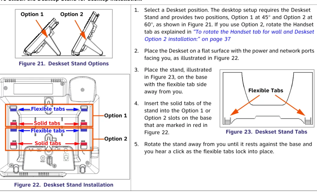
Figure 21. Deskset Stand Options
Figure 22. Deskset Stand Installation
1. Select a Deskset position. The desktop setup requires the Deskset Stand and provides two positions, Option 1 at 45° and Option 2 at 60°, as shown in Figure 21. If you use Option 2, rotate the Handset tab as explained in “To rotate the Handset tab for wall and Deskset Option 2 installation:” on page 37
2. Place the Deskset on a flat surface with the power and network ports facing you, as illustrated in Figure 22.
3. Place the stand, illustrated in Figure 23, on the base with the flexible tab side away from you.
4. Insert the solid tabs of the stand into the Option 1 or Option 2 slots on the base that are marked in red in Figure 22.
5. Rotate the stand away from you until it rests against the base and you hear a click as the flexible tabs lock into place.
Option 1 Option 2 Option 1 Option 2 Flexible tabs Flexible tabs Solid tabs Solid tabs
Figure 23. Deskset Stand Tabs Flexible Tabs
To rotate the Handset tab for wall and Deskset Option 2 installation:
Figure 24. Handset Tab
1. Press the switch hook and slide the Handset Tab toward the top of the base, as shown in Figure 24.
2. Rotate the Handset Tab 180°, as shown in Figure 25, so that the “hook” is at the top.
3. Slide the Handset Tab back into the base, as shown in Figure 26.
Figure 26. Replace Handset Tab Handset Tab Switch hook
Figure 25. Handset Tab Rotation “Hook”
To connect the Cat.-5 LAN cable to the Deskset:
With a PC:
If there is a networked computer and no extra Ethernet wall jacks near the Deskset, then plug the PC Ethernet cable into the Deskset so the Deskset and PC share the same network connection.
1. Unplug the Cat.-5 Ethernet cable from your computer.
2. Plug that Cat.-5 Ethernet cable into the Network port on the back of the Deskset, as indicated in Figure 27.
3. Plug another Cat.-5 Ethernet cable into the PC port on the Deskset. 4. Plug the other end of the second Cat.-5 Ethernet cable into your computer.
If a GigE network is being used, a computer connected through the
Deskset will be limited to 100 Mbits/s. If you require a GigE Ethernet rate, use separate Ethernet connections for the Deskset and the computer so that the computer can take advantage of the greater bandwidth.
If a PC is connected to your LAN through a Deskset, any Deskset resets and power or network interruptions will disrupt the PC’s connection to the network.
Network PC
Figure 27. Network Connections
The PC port on the Deskset is intended for connection to an end-user PC only.
Do not use the PC port to connect to a PC with a heavy bandwidth load (such as a network server PC or a hub, switch, or router).
Do not use the PC port to extend the network. The end-user PC should be the final point. Do not use the PC port to connect to other system devices.
To connect the Cat.-5 Ethernet cable to the Deskset: (Continued)
Without a PC
If the Deskset has a dedicated network connection, then connect the Deskset to the network connection only.
1. Plug a Cat.-5 Ethernet cable into the Network port on the back of the Deskset, as indicated in Figure 27 on page 38. 2. Plug the other end into the Ethernet wall jack.
To connect power:
Figure 28. Power Connector
[020] If you are using PoE, connecting the Deskset to the network also connects the power.
If you are using the supplied power adapter:
1. Plug the power adapter (blue tag) into the DC Power jack on the back of the Deskset, as identified in Figure 28.
2. Plug the power adapter into an outlet not controlled by a wall switch. The display screen illuminates within about a minute. If the user's computer is plugged into an uninterruptible power supply (UPS), consider plugging the Deskset into it, too.
To install the Deskset on a wall:
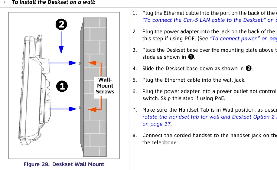
Figure 29. Deskset Wall Mount
1. Plug the Ethernet cable into the port on the back of the deskset. (See
“To connect the Cat.-5 LAN cable to the Deskset:” on page 38.) 2. Plug the power adapter into the jack on the back of the deskset. Skip
this step if using POE. (See “To connect power:” on page 39.) 3. Place the Deskset base over the mounting plate above the mounting
studs as shown in .
4. Slide the Deskset base down as shown in . 5. Plug the Ethernet cable into the wall jack.
6. Plug the power adapter into a power outlet not controlled by a wall switch. Skip this step if using PoE.
7. Make sure the Handset Tab is in Wall position, as described in “To rotate the Handset tab for wall and Deskset Option 2 installation:” on page 37.
8. Connect the corded handset to the handset jack on the left side of the telephone.
Wall-Mount Screws
To connect the corded handset and an optional corded headset
Figure 30. Handset Cord Connection
Connect the corded handset:
1. Plug the coiled end of the handset cord into the handset jack on the left side of the telephone, as identified in Figure 30.
2. Plug the end of the handset cord with the longer straight portion into the handset, then hang up.
Connect an optional corded headset:
Plug an optional corded headset or cordless headset base into the
RJ-9 connector on the bottom of the Deskset, as indicated in Figure 31.
[030] A headset plugged into this jack takes precedence over a registered AT&T TL7600 Cordless Headset.
Handset Jack on Handset
Handset Jack On Deskset
Optional Headset Jack
Do not plug a headset into the jack for the corded handset.
SB67050 ATA Installation
To install the ATA:
1. After installing at least one Deskset, plug the AC plug into an electrical outlet not controlled by a wall switch and the DC plug into the DC jack, as shown in Figure 32. Wait up to one minute until the screen lights up.
2. Plug a Cat.-5 Ethernet cable into the port marked LAN. Plug the other end of the Ethernet cable into your office LAN.
Figure 32. ATA Power, LAN, and Station Port Connections
The ATA takes about a minute to power up.
After the ATA has found the network and the Gateway, Synchronized appears on the third line of the display, as shown in Figure 33. This is the Idle screen.
The time and date may not be correct. The time and date are set using the WebUI. See
“System Settings” on page 85.
3. Remove the plastic covers from the FXS station ports that you are using, as shown in Figure 32.
To prevent the loss of ATA-supported services during power outages, plug the AC power plug into an Uninterruptible Power Supply (UPS).
LAN DC Power
FXS 2 FXS 1
Station Ports AUX IN AUX OUT
Connecting Analog Devices to the ATA
The ATA allows you to attach the following analog devices to the ports and jacks identified in Figure 32 on page 42. Most options require the system administrator to configure the feature in the WebUI. If you are planning to install more than one type of analog equipment, make sure there are suitable ATA ports available.
Analog telephones, including conference phones
If not used for a fax machine or for Overhead Paging, the two FXS station ports on the ATA allow for connecting standard POTS (Plain Old Telephone Service) analog telephones and conference phones. When an ATA is added to the Synapse system, the FXS ports are automatically assigned extension numbers that can be changed by the system administrator using the WebUI. Users can make and receive calls on those analog telephones, but some features, such as call forward and call transfer, are not supported.
An analog telephone connected to an FXS port can be used for Private Line Automatic Ringdown (PLAR). When you enable the PLAR feature through the WebUI, an analog telephone or device connected to an ATA FXS port will ring a destination when it goes off hook. The destination can be an extension or a ring group. See “ATA Settings” on page 106.
A fax machine to share your general telephone lines instead of using a dedicated fax line
One of the two FXS station ports can be configured to support a fax machine. The system administrator must configure the Fax mode in the WebUI.
Overhead Paging Equipment (OHP)
The ATA provides three options to connect OHP. The system administrator must configure the OHP in the WebUI. Single-zone paging with OHP equipment connected to the ATA Aux Out jack
Single-zone paging with OHP equipment connected to one of the FXS station ports Multi-zone paging with OHP equipment connected to one of the FXS station ports. A source for Music On Hold (MoH)
You can use the ATA to route MoH audio input to outside held and parked calls. When external callers are placed on hold or “parked,” they hear the audio source provided by the MoH input. The system administrator must configure the MoH in the WebUI.
See “The Web User Interface (WebUI)” on page 80 for information on configuring and using third-party devices.
Connecting Analog Telephones
To install analog telephones:
1. Remove the plastic covers from the FXS 1 and FXS 2 (telephone) ports to be used on the ATA.
2. Plug up to two telephone lines from analog telephones into the ATA FXS 1 and FXS 2 ports, as shown in Figure 34.
Figure 34. ATA Analog Telephone Installation Figure 35. ATA Analog Telephone/ Conference Phone Analog Telephone/ Conference Phone
Connecting a Fax Machine
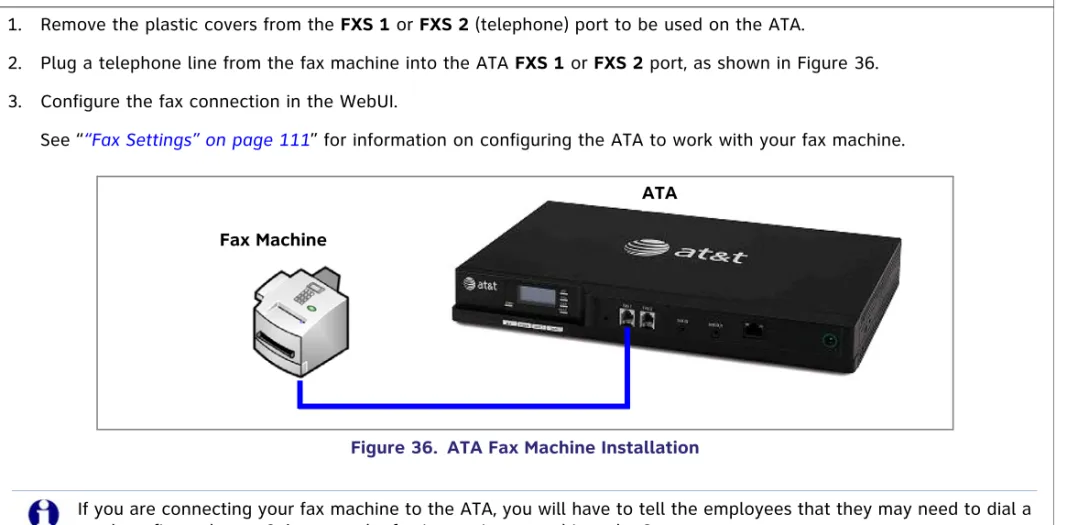
To install a fax machine:
1. Remove the plastic covers from the FXS 1 or FXS 2 (telephone) port to be used on the ATA.
2. Plug a telephone line from the fax machine into the ATA FXS 1 or FXS 2 port, as shown in Figure 36. 3. Configure the fax connection in the WebUI.
See ““Fax Settings” on page 111” for information on configuring the ATA to work with your fax machine.
Figure 36. ATA Fax Machine Installation Fax Machine
ATA
If you are connecting your fax machine to the ATA, you will have to tell the employees that they may need to dial a trunk prefix, such as a 9, because the fax is now integrated into the Synapse system.
Connecting an Overhead Paging System (OHP)
A Single Zone or Multi-Zone system can be integrated into an existing Synapse network. The control unit or analog amplifier for the Overhead Paging system connects directly to the ATA via an FXS or the AUX OUT jack, depending on the type of paging system. Synapse supports most OHP systems that support PBX station ports or auxiliary audio-out connections to a PBX. Some settings for the OHP may have to be changed to work with Synapse. The following OHP systems have been verified to work with Synapse.
If you don't know whether your OHP is Single Zone or Multi Zone, see “Overhead Paging Overview” on page 112“. There are so many types of paging equipment that you may need to contract with a communications equipment professional to install the OHP.
Single Zone Multi-Zone
Aux Out Jack
Bogen TPU35B FXS Port
Bogen TAMB Bogen TPU15A
Bogen TPU35B (alternate to TPU15A) Valcom 1030c
Viking CPA-7B
Valcom V-9940 (expandable for multi-zone) Valcom V-9941A (with talkback)
FXS Port
Bogen PCM 2000 Bogen PCM TAMB
Bogen TPU15A or TPU35B Bogen ZPM3
Whether you are replacing a phone system and using an existing (already working) OHP, or installing a new OHP, the paging system may have settings that need to be adjusted to work with Synapse.
OHPs that are “Line Mode” that cannot be set to “Station Mode” cannot be used with Synapse.
To install an overhead paging system:
1. Remove the plastic cover from the FXS 1 or FXS 2 port to be used on the ATA.
2. Plug the telephone line from the OHP device into the FXS 1 or FXS 2 port, or plug an audio cable from the OHP device into the Synapse AUX OUT jack, as shown in Figure 37, depending on the requirements of the paging system.
3. Enable the OHP device in the WebUI.
See the “The Web User Interface (WebUI)” on page 80 for information on configuring an OHP device.
Figure 37. ATA Overhead Paging System Installation Overhead
Paging System
ATA
Audio Cable Connection FXS Connection
Connecting a Music on Hold Source
To install a music on hold source:
1. Use the supplied Auxiliary Audio Cable to plug a streaming audio source, such as a radio or MP3 music player, into the ATA AUX IN jack as shown in Figure 38. If the supplied cable does not connect to your music source, use another cable that will connect your device to the 3.5 mm AUX IN jack. This audio source must have a volume control. The volume adjustment on the audio device should be set to obtain the preferred level of music on hold within the system.
2. Enable Music on Hold in the WebUI.
See “The Web User Interface (WebUI)” on page 80 for information on configuring an OHP device.
Figure 38. ATA Music on Hold Source Installation
The ATA AUX IN jack is set up to receive headset-out audio signals. Do not connect to a “Line-Out” audio source or to speaker outputs.
On-hold music functionality should only be used in conjunction with music specifically licensed for on-hold use. Licensed on-hold music is available from many third-party suppliers. AT&T disclaims any liability arising from the failure to obtain such a license.
Music on Hold Source ATA
SB67040 Cordless Handset Installation
Charger Installation
Place the Handset in the charger when not in use. To plug the Handset charger into AC power:
Figure 39. Handset Charger Power Connect
1. Plug the power adapter into an electrical outlet not controlled by a wall switch.
2. Plug the small end of the power adapter into the jack on the underside of the charger.
3. Route the cord through the slot, as shown in Figure 39.
The SB67040 Cordless Handset requires registration to an SB67030 Deskset. The SB67020 Deskset does not support the SB67040 Cordless Handset.
Battery Installation
The Handset uses a rechargeable 2.4v nickel-metal hydride cell (NiMH) battery pack. To install the Handset battery:
Figure 40. Install Handset Battery
1. Remove the battery cover by pressing and sliding the cover downward, as shown in Figure 40.
2. Plug the battery connector securely into the plug inside the Handset battery compartment, matching the color-coded label.
3. Place the battery in the compartment with THIS SIDE UP facing up. 4. Align the cover flat against the battery compartment, then slide it upward
until it clicks into place.
If the battery has enough charge, within 10 seconds the LCD displays the
Place in charger screen shown in Figure 41. If there is no charge, the
screen remains blank.
5. Place the Handset in the charger.
Figure 41. Place in Charger Color-Coded
Battery Connector
Use only the supplied rechargeable battery or replace it with battery model BT8001. To obtain a replacement battery, visit our website at
www.telephones.att.com/smb or call
1 (888) 916-2007
. In Canada, dial1 (888) 883-2474
.12:00a Jan. 00 12:00a Jan. 00
Battery Charging
Charge the Handset battery for at least 16 hours before use. When fully charged, the Handset battery provides approximately five hours of talk time or three days of standby time.
To charge the Handset battery:
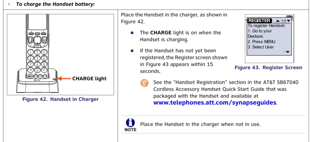
Figure 42. Handset in Charger
Place the Handset in the charger, as shown in Figure 42.
The CHARGE light is on when the
Handset is charging.
If the Handset has not yet been registered, the Register screen shown in Figure 43 appears within 15 seconds.
See the “Handset Registration” section in the AT&T SB67040 Cordless Accessory Handset Quick Start Guide that was packaged with the Handset and available at
www.telephones.att.com/synapseguides
. CHARGE light 12:00a Jan. 00 12:00a Jan. 00 To register Handset: 1. Go to your Deskset. 2. Press MENU. 3. Select User REGISTER 1/3Figure 43. Register Screen
TL7600 Cordless Headset Installation
Charger Installation
The TL7600 cordless headset requires registration to an SB67030 Deskset. The SB67020 does not support the TL7600 cordless headset.
To install the TL7600 charger:
Figure 44. Charger Installation
1. Plug the small end of the charger power adapter into the jack on the underside of the charger, then route the cord through the slot as shown in Figure 44. 2. Plug the large end of the charger power adapter into an AC wall outlet not
controlled by a wall switch.
Battery Installation
Install the battery as shown below. For optimal performance, charge the Headset battery for at least six hours before use. When not in use, recharge the Headset by returning it to the Headset charger.
To install a battery:
Figure 45. Remove Battery Door
Figure 46. Insert Battery and Plug
1. If the battery door is attached, press on both sides of the battery
compartment cover and lift the cover up and off as shown in Figure 45. 2. Insert the battery into the battery
compartment with the label THIS SIDE UP facing up as shown in Figure 46.
3. Push the battery plug into the connector inside the compartment
according to the color-coded label and place the wires neatly inside the compartment as shown in Figure 46.
4. Insert the tab on the bottom of the battery cover into the battery compartment. Press down gently on the battery cover until it snaps into place as shown in Figure 47.
Insert Battery Insert Plug
Figure 47. Replace Battery Door
Remove the ear hook from the Headset before battery replacement. Use only the supplied rechargeable battery or replace it with battery model BT191545. To obtain a replacement battery, visit our website at
www.telephones.att.com/smb or call
1 (888) 916-2007
. In Canada, dial1 (888) 883-2474
.Battery Charging
After installing the battery, charge the Headset by placing it in the Headset charger as shown below. Before registration, the Headset ON/OFFlight flashes twice every five seconds whether the Headset is charging or not. After registration, the Headset
ON/OFF light is on when the Headset is charging. To charge the battery:
Figure 48. Insert Headset
1. Insert the Headset into the charger as shown in Figure 48.
2. Push the Headset downward until the ON/OFF
light on the Headset turns on as shown in Figure 49.
If the Headset has not yet been registered, the
ON/OFF light flashes blue and orange. To register the headset, use the process described in “Registering an Optional Cordless Headset” in the AT&T SB67030 Deskset and Accessories User’s Guide at
www.telephones.att.com/
synapseguides.
Figure 49. Headset ON/OFF Light ON/OFF Light
C
H A P T E R
2
G
ETTING
S
TARTED
This chapter gets you started with configuring the Synapse system from the devices. Most of these functions are duplicated in the easier-to-use WebUI described in the next chapter, but if you need to assign static IP addresses, they must be set at each device. You can only directly reset a device from the device, although some functions in the WebUI include device resets.
This chapter covers:
“PSTN Gateway Features” on page 56 “T1 Gateway Features” on page 58
“Gateway Front Panel Interface” on page 60 “Deskset IP Settings” on page 73
“Upgrade Deskset Software” on page 77 “ATA Features” on page 65
30)(%
3671/LQHV
6\QFKURQL]HG
,3
PSTN Gateway Features
Figure 50 illustrates the PSTN Gateway features and connections.
Figure 50. PSTN Gateway Features and Connections
1. Display Provides system and network status, device information, and configuration data. See
“Gateway Front Panel Interface” on page 60.
2. Reset When pressed momentarily, restarts the Gateway.
When pressed and held for more than five seconds and with the LAN cable not connected, restores factory defaults.
3. PSTN Line Ports 1–4 Traditional 2-conductor wiring (FXO—Foreign Exchange Office Ports).
4. Bypass Port Traditional analog POTS (Plain Old Telephone Service) that is available during an AC power
outage. When the Gateway power fails, calls on Line 4 are routed to the bypass line.
5. RJ-45 Ethernet Network Port 10Base-T/100Base-Tx with Auto MDI/MDI-X switching.
6. DC 5.1V Power-Supply Jack
DC 5.1V LINE 1 LINE 2 LINE 3 LINE 4 BYPASS
LAN RESET LINE 1 LINE 2 LINE 3 LINE 4 POWER SELECT CANCEL DOWN UP + -1 2 3 4 5 6
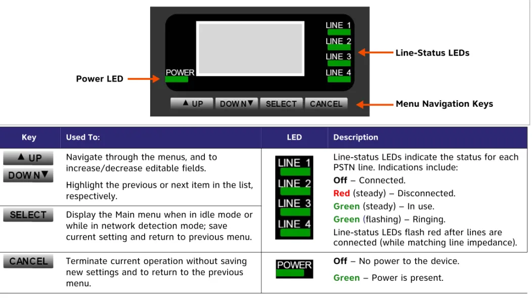
Figure 51 provides an illustration and description of the PSTN Gateway front panel.
Figure 51. PSTN Gateway Front Panel Description
Key Used To: LED Description
Navigate through the menus, and to increase/decrease editable fields.
Highlight the previous or next item in the list, respectively.
Line-status LEDs indicate the status for each PSTN line. Indications include:
Off – Connected.
Red(steady) – Disconnected. Green (steady) – In use.
Green (flashing) – Ringing.
Line-status LEDs flash red after lines are connected (while matching line impedance).
-
Display the Main menu when in idle mode or while in network detection mode; save current setting and return to previous menu. Terminate current operation without saving new settings and to return to the previous menu.
Off – No power to the device. Green – Power is present.
Power LED
Line-Status LEDs
T1 Gateway Features
Figure 52 illustrates the T1 Gateway features and connections.
Figure 52. T1 Gateway Features and Connections
1. Display Provides system and network status, device information, and configuration data. See
“Gateway Front Panel Interface” on page 60.
2. Reset When pressed momentarily, restarts the Gateway.
When pressed and held for more than five seconds and with the LAN cable not connected, restores factory defaults.
3. T1 Port
4. RJ-45 Ethernet Network Port 10Base-T/100Base-Tx with Auto MDI/MDI-X switching.
5. DC 12V Power-Supply Jack 1
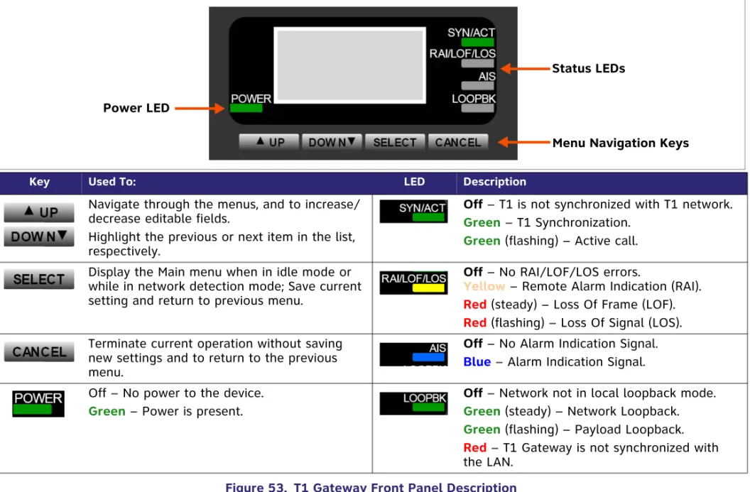
Figure 53 provides an illustration and description of the T1 Gateway front panel.
.
Key Used To: LED Description
Navigate through the menus, and to increase/ decrease editable fields.
Highlight the previous or next item in the list, respectively.
Off – T1 is not synchronized with T1 network. Green – T1 Synchronization.
Green (flashing) – Active call. Display the Main menu when in idle mode or
while in network detection mode; Save current setting and return to previous menu.
Off – No RAI/LOF/LOS errors.
Yellow – Remote Alarm Indication (RAI). Red (steady) – Loss Of Frame (LOF). Red (flashing) – Loss Of Signal (LOS). Terminate current operation without saving
new settings and to return to the previous menu.
Off – No Alarm Indication Signal. Blue – Alarm Indication Signal. Off – No power to the device.
Green – Power is present.
Off – Network not in local loopback mode. Green (steady) – Network Loopback. Green (flashing) – Payload Loopback. Red – T1 Gateway is not synchronized with the LAN.
Power LED
Status LEDs
Gateway Front Panel Interface
You can access basic information and perform some configuration tasks using the Gateway’s front panel. Most of these tasks are easier to do using the WebUI. See “The Web User Interface (WebUI)” on page 80.
The Gateway displays the Idle screen upon completion of the power-up sequence. Use the Gateway Main menu to perform some system operations.
Figure 54. Gateway Idle Screens
To access the Gateway Main menu from the Idle screen, as shown in Figure 54, press the key. The menu provides the following functions:
Device Information Network Status Configuration