A Formal Framework for Network Security
Design Synthesis
Mohammad Ashiqur Rahman and Ehab Al-Shaer
Department of Software and Information Systems, University of North Carolina at Charlotte, United States Emails:{mrahman4, ealshaer}@uncc.edu
Abstract—Due to the extensive use of Internet services and emerging security threats, most enterprise networks deploy varieties of security devices for controlling resource access based on the organizational security requirements. These requirements are becoming more fine-grained, where access control depends on heterogeneous isolation patterns like filtering network traffics, trusted communication, and payload inspection. However, today organizations are looking to design usable and optimal security configurations that can harden the network security within enterprise budget constraints. It requires analyzing various alternative security architectures in order to find a security design that satisfies the organizational security requirements as well as the business constraints. In this paper, we present
ConfigSynth, an automated framework for synthesizing network security configurations by exploring various security design al-ternatives to provide an optimal security design. The main design alternatives include different kinds of isolation patterns for traffic flows in different segments of the network. ConfigSynth takes security requirements in terms of isolation, business constraints in terms of usability and deployment cost, along with the network topology, as inputs. Then it synthesizes optimal and cost-effective security configurations satisfying the constraints. ConfigSynth also provides optimal placements of different se-curity devices in the network according to the given network topology. ConfigSynth usesSatisfiability Modulo Theories(SMT) for modeling this synthesis problem. The scalability of the tool is also demonstrated using simulated experiments.
Keywords-security; configuration synthesis; formal logic.
I. INTRODUCTION
Today, the organizational security requirements are very complex due to extensive use of various network services and newly evolving security threats. In addition, most of the organizations are not only emphasizing the enforcement of the security requirements but also requiring satisfaction of different business constraints on usability and security deployment cost. The problem of providing a strong security in a network by exploring different security design alternatives, as well as resolving the contention between the security and business constraints is important but challenging.
Usually, the organizational security requirements indicate
isolation measures between the hosts. The isolation patterns are defined based on different security devices and their capabilities. An isolation pattern signifies the type of security resistance, e.g., traffic filtering (firewall), trusted communica-tion (IPSec), payload traffic inspeccommunica-tion (IDS), hiding traffic source identity (NAT), etc. However, any security design has to satisfy the business constraints of the organization, which are represented in terms ofusabilityanddeployment cost. The
connectivity requirements fall under usability, which define the essential service flows between various network devices. The implementation of isolation measures significantly affects these constraints. For example, the use of both IPSec and IDS based isolation patterns might reduce the usability by causing some applications to be inaccessible for a host, while the use of firewall based access denial would give no usability. Hence, it is required to find security configurations by exploring differ-ent security design alternatives that maintain the security and usability within an expected level. Moreover, the deployment of a security device has a cost. Hence, it is also required to find the best security isolation design at an affordable cost.
In this paper, we presentConfigSynth, an automated frame-work for synthesizing netframe-work security configurations and physical placements of security devices, using constraint sat-isfaction checking. ConfigSynth takes a network topology, security requirements, and business constraints as inputs, and formulates thesecurity design synthesis problem. ConfigSynth solves the problem by encoding the model into Satisfiability Modulo Theories (SMT) [1]. ConfigSynth is a novel frame-work that incorporates the security device placements in the network topology within the design in order to model the de-ployment cost, which is crucial for a security architecture. The framework can be used as a decision support system to create optimal security configurations for a network by exploring different design alternatives. The evaluation of ConfigSynth shows that it can synthesize optimal security configurations of a network with several thousands of service flows.
The rest of this paper is organized as follows: The architec-ture of ConfigSynth. is presented in Section II The modeling of the security design synthesis problem is described in Section III. The implementation of ConfigSynth is discussed in Section IV. The evaluation results of our model are presented in Section V. The related works are discussed in Section VI. Finally, conclusions are drawn in Section VII.
II. CONFIGSYNTHARCHITECTURE
ConfigSynth follows a top-down security design automation approach instead of the traditional bottom-up approach. The major contributions of ConfigSynth are as follows:
• Formally models the network topology, security (i.e., isolation) requirements and business (i.e., usability and deployment cost) constraints.
• Formalizes the security design synthesis problem as the determination of appropriate isolation patterns along
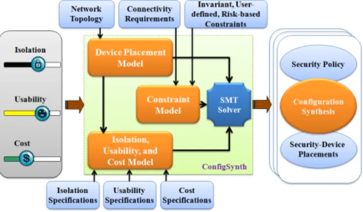
Fig. 1. The architecture of ConfigSynth.
with the correct placements of necessary security de-vices in the network that satisfies the given require-ments/constraints.
• Encodes the synthesis problem into SMT logics and solves it using an SMT solver.
The ConfigSynth architecture is shown in Fig. 1. Con-figSynth takes the following as its main inputs: (i) the net-work topology, (ii) security (isolation) requirements, and (iii) business (usability and deployment cost) constraints. The tool provides its user with three sliders in order to select the constraints on the isolation measure taken in the network, the usability of the system, and the cost for deploying necessary security devices. The sliders are scaled from 0 to some bound. The tool also takes necessary specifications (usually partial information), especially about the isolation patterns and demand of different flows. The isolation requirements are conditioned on the specifications of different primitive and composite isolation patterns along with their relative order based on their capabilities. ConfigSynth models the functional mapping from each flow to an isolation decision variable. Finally, it represents the overall isolation measure taken in the network by accumulating isolation measures between different host pairs under various services.
The usability is modeled based on the connectivity re-quirements and the ranks of the services and service flows as provided in the specifications. The connectivity require-ments, which are modeled as a set of rules, where each rule functionally maps a flow to a decision variable. We model impacts of different isolation patterns on the usability. The deployment of isolation measure is associated with a cost. The cost depends on the security devices required for implementing the isolation patterns. The number of security devices depends on the network topology. ConfigSynth also models different invariant and user-defined constraints on selecting the security design. ConfigSynth formalizes the security design synthesis problem as the conjunction of all of the isolation, usability, and cost constraints. Therefore, the tool determines the isolation patterns between each service flow in the network, such that the overall isolation in the network and the usability of the system satisfy the associated constraints, while the cost for security deployment does not exceed the budget. ConfigSynth solves this security design synthesis problem using Z3, a powerful SMT solver [2].
III. SECURITYDESIGNSYNTHESISMODEL
ConfigSynth models the network topology as a graph. The network model is defined as⟨N,L⟩, where,
• N defines a finite set of network nodes including hosts and routers. Thus, N is a union of two sets: H and R. Hdenotes a finite set of hosts.R denotes a finite set of routers. Each host is identified by an ID (e.g., IP address). A host may execute one or more services, which are accessed by different hosts. A service is denoted using
g∈G, whereGis the set of all services. The termg(i, j) defines the flow between a pair of hosts {i, j}, wherei
is the source and j is the destination, under a serviceg.
• L ⊆ N×N is a finite set of links, which defines the interconnections between the network hosts.
ConfigSynth formalizes different requirements and con-straints which are the building-blocks for formulating the configuration synthesis problem. The requirements can be classified into two categories: (i) security requirements, and (ii) business constraints. There are also invariant and user-defined constraints on security implementations.
A. Formalizing Security Requirements: Isolation
The more a host is isolated from other hosts in the net-work, the potential threat to security becomes less. We define
isolation as the restriction on the connectivity, i.e., network communication. The communication between two hosts can be restricted applying different security devices or systems, such as firewall, IPSec, IDS, NAT, etc. For example, a firewall can be placed to simply block some traffic flows (i.e., complete isolation), while IPSec can be placed to ensure authenticated transmission for the allowed flows (i.e., restriction based on authorization) in a network segment. Both of these devices are required to ensure authenticated and controlled traffic flow.
In order to formalize isolation, it is required to define different isolation patterns considering the security devices, the levels of restrictions they enforce on the flows (i.e., their effectiveness on the isolation), and their impact on the usability. The objective of isolation requirement is to have fine-grained security measures in the network. Therefore, it is required to devise an appropriate combination of security devices for providing fine-grained security controls.
Isolation Patterns: Isolation patterns can be network level, host level, or application level. In this research, we consider the network level isolation, which includes the following patterns:
• Access deny. This is naturally enforced by a firewall.
• Trusted communication, i.e., authenticated and encrypted communication. IPSec devices are used to build trusted path (a.k.a. tunnel).
• Payload inspection. This is done by an intrusion detection system (IDS).
• Source identity hiding. A network address translation (NAT) device is applied in order to use different ad-dress (typically a real IP adad-dress) instead of the original address. With respect to security, it can give security
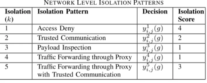
TABLE I
NETWORKLEVELISOLATIONPATTERNS
Isolation (k)
Isolation Pattern Decision Isolation
Score
1 Access Deny yi,j1 (g) 4 2 Trusted Communication y2
i,j(g) 2 3 Payload Inspection y3
i,j(g) 1 4 Traffic Forwarding through Proxy y4
i,j(g) 1 5 Traffic Forwarding through Proxy
with Trusted Communication y5
i,j(g) 3
ensuring one way communication (i.e., internal hosts to external hosts). The same can be ensured by a firewall.
• Traffic forwarding through Proxy. For example, a reverse proxy gives a layer of security in terms of traffic filtering or implementing access control rules (ACLs) in the proxy instead of the server.
ConfigSynth allows network administrators to define isola-tion patterns considering different security devices (primitive isolation) and their combinations (composite isolation), along with their relative order based on the capabilities and func-tionalities of the devices. A set of primitive isolation patterns is shown in Table I. Each pattern is represented using an ID,
k. As shown in the table, k = 1 denotes ’access deny’ and
k= 2 for ’trusted communication’, and so on. We formalize the isolation measures (i.e., the security configurations) as a set of rules, {IR1, IR2, .., IRn}, where each isolation rule
IRris defined as follows:
IRr:yki,j(g),where,i, j∈Handg∈G The variable, yk
i,j(g)indicates that corresponding k’th iso-lation pattern is required to be deployed between the host pair {i, j}for serviceg. Note that a host can represent a group of hosts that have the same properties (e.g., OS, services, etc.), the same level of users, and reside in the same subnet. Isolation Pattern and Security Device: An application of an isolation pattern requires the deployment of one or more security devices. Usually, an isolation pattern is related to a particular type of security device. This one-to-one matching is true for primitive isolation patterns. In case of a composite isolation pattern, it is required to deploy more than one se-curity device. The following equation models the relationship between an isolation pattern and associated security device(s):
∀i,j,g, yi,jk (g)⇒x d
i,j(g) (1)
Equation (1) specifies that if k’th isolation is selected for
g(i, j) flow, the d’th (type of) security device is required to be deployed between the host pair {i, j} (i.e., on the route of the flow). A particular value of d denotes a particular type of security device. For example, as shown in Table II,
d= 1 represents a firewall security device. If k’th pattern is a composite isolation pattern, multiple security devices are required to implement the isolation pattern. Hence, in this case, multiple xd
i,j(g)s are true. Usually, a security device deployment depends on the isolation pattern only, not on the flows (i.e., i, j, or g). Equation (1) considers this. Table II shows a list of network security devices and the associated primitive isolation patterns.
TABLE II SECURITYDEVICES
Id (d) Device Name Primitive Isolation Pattern
1 Firewall Access Deny
2 IPSec Trusted Communication 3 IDS Payload Inspection
4 Proxy Traffic Forwarding through Proxy
Score of an Isolation Pattern:We define the isolationscore
(also named asrank) of thekth isolation pattern between a pair of hosts{i, j} under the network serviceg by the parameter
Lki,j(g). The score of an isolation pattern denotes its isolation capability compared to others. The scores are computed based on the relative order of the isolation patterns according to their isolation capabilities. An administrator can provide the relative order explicitly or a partial information about the order. A simple formal model is developed based on the given partial order between different isolation patterns. The model generates a complete relative order by assigning a value to each isolation pattern. The value assigned to a pattern denotes its (relative) isolation score. The highest value specifies the maximum isolation score. It is plausible to assume the same score (Lk) for a particular isolation pattern irrespective of hosts and services. Table I shows an example of relative isolation scores from the following partial information:
∀k̸=1, Lk< L1
(L2> L3)∧(L2> L4)∧(L5> L2)
The isolation scores are normalized according to a specified range, e.g., a scale of 0−1. Note that this scoring of isolation patterns is relative and security requirements based on this scoring system reflects the same relative meaning.
Isolation of a Host:The decision variablesyk
i,j(g), for allk, represent isolation patterns between a pair of hosts {i, j}
for the flow g(i, j). These decision variables and associated isolation weightsLk
i,j(g)are used to formally define the total isolation (I¯i,j) ofjwith respect to the incoming traffic fromi.
¯
Ii,j is formalized as follows:
¯ Ii,j= ∑ g ∑ kyi,jk (g)×Lki,j(g) ∑ g ∑ ky k i,j(g)×1
The equation indicates that the isolation between a pair of hosts {i, j} is the sum of the isolation measures taken for different services between these hosts. The equation also indicates that the isolation is normalized by dividing the sum by the maximum possible isolation (i.e., the maximum isolation for a flow g(i, j) is 1 in the scale of 0−1). We consider the similar normalization throughout the model. For the ease of presenting the equations, we do not show the normalization factors (i.e., the denominators at the right hand side of the equations) for the rest of the paper.
The isolation of a host depends not only on the hosts that can connect to it. The isolation also depends on the hosts that it can connect to. For example, if a host can connect to the Internet, the host can download malicious content from the Internet and can get infected. However, the impact of such communication is less compared to the communication coming from the other direction. Since the outgoing traffic fromj to
i is the incoming traffic for i from j, the total isolation Ii,j considering both the incoming and the outgoing traffic with respect to j for the pair of hosts{i, j}is defined as follows:
Ii,j=αI¯i,j+ (1−α) ¯Ij,i (2)
Here, α(0≤α≤1) is the weight for the isolation due to the incoming traffic, while1−αis the weight for the isolation due to the outgoing traffic. The total isolation score of a host
j is defined in (3).
Ij=
∑
i̸=j
Ii,j (3)
Equation (4) represents theoverall isolation in the network
(i.e., the network isolation) considering all of the hosts.
I=∑
i
Ii (4)
B. Formalizing Business Constraints: Usability
Business constraints play a significant role in synthesizing usable and cost-effective security configurations in a network. For example, a higher isolation can provide strong defense in the network, but the usability of the network might reduce to a level which is unacceptable to the organization. Resolving the contention between security requirements and business constraints is a challenge. In ConfigSynth, we formalize the synthesis problem under two business constraints: (i) usability and (ii) deployment cost. In this subsection, we discuss the formalization of the usability.
Connectivity Requirements:Every organization usually has a number of service flows, which are essential for its successful operation. Each of theseconnectivity requirementsrepresents a flow that must be able to communicate. Connectivity require-ments are formalized as a set of rules {CR1, CR2, .., CRn}, where each connectivity rule,CRr defines the mapping from a flow (i.e., a tuple of source, destination, and service) to a decision variablecthat represents whether the flow is required to be allowed. The formal definition ofCRr is as follows:
CRr:cai,j(g),where, i, j∈Handg∈G
Here,acan have two values (binary): 1 and 0. The value 1 represents that the servicegmust flow fromitoj. The value 0 means nothing has been specified for this flow, i.e., the flow can be allowed or denied. CR represents the conjunction of all connectivity requirement rules.
CR⇒∧
r
CRr (5)
Usability Computation:The usability of the network depends on the ranks of the service flows between the hosts in the network. The rank of a service flow denotes the demand of the flow. Each service flow g(i, j) is associated with a rank, ai,j(g). These ranks are expected to be given in the form of a relative order by the administrator based on the organizational demand. Partial information can be given, from which a complete relative order can be derived, as it has been shown in the case of the isolation patterns. If no specification
is given about the demand of different flows, all flows receive the same rank. The ranks are normalized between 0 to 1. The usability of a serviceg in a hostj is formalized as follows:
Sj(g) = ∑ i ∑ k bki,j(g)×ai,j(g)
The application of an isolation pattern to a flow can affect the usability of the flow. The parameter bki,j(g) represents the usability of the flow g(i, j) due to applying the k iso-lation pattern between {i, j}. We assume that the usability depends on the isolation pattern, not on the host-pair (i.e.,
bk
i,j(g) =bk(g)). The value ofbk(g)can be determined based on the prior knowledge of network security by considering the time or effort required to get a service access under an isolation measure. The valuation of the parameterbk(g), in the simplest form, can be as follows: the ’access deny’ isolation pattern reduces the usability to zero, i.e., ∀g, b1(g) = 0; while other isolation patterns maintain the same usability, i.e., ∀g,k̸=1, bk(g) = 1. The usability Sj with respect to a host
j represents the accumulated usability considering all of the services running in the host.
Sj =
∑
g
Sj(g)
The overall usability of the network (i.e., the network usability) is represented by (6).
U =∑
j
Sj (6)
C. Formalizing Business Constraints: Deployment Cost
The deployment of a security device incurs costs and an organization often has an afford limit for deploying security measures. The deployment cost is the sum of the prices of the security devices that are required to be deployed in different segments of the network in order to implement necessary isolation patterns between different host-pairs. The number of security devices depends not only on the isolation measures but also on the topology. The cost cannot be figured out from the isolation measures alone. This is because of the fact that there are usually similar types of isolation between multiple host-pairs and these host-pairs can share one or more links for communication. In this case, placing a single security device at one of the shared links may ensure the desired isolation. Moreover, if there is more than one routing path between a host-pair, we have to secure all of the alternative paths. Therefore, modeling correct and optimal placements of the security devices considering the network topology, the isolation patterns, and the budget is very challenging. Modeling Flow Routes:ConfigSynth requires the flow routes between the hosts for determining the placements of the security devices satisfying the isolation measures. A flow route,Fz
i,j is defined as a set of links{li,j,z,1, li,j,z,2, ...} ⊆L, that form a path from a sourceito a destinationj. As multiple routes are possible between a pair of hosts, z indicates the index of the flow route (i.e., thez’th route), between the host-pair {i, j}. The term |Fz
number of hops or links in the path. Fi,j denotes all of the flow routes possible from itoj.
Fi,j ⇒
∧
z
Fi,jz
ConfigSynth finds the flow routes for a host pair by applying a path searching algorithm on the network topology.
Formalizing Device Placements: Equation (1) specifies the security devices which are required to employ an isolation pattern. The placements of the security devices on the flow routes are modeled from these specifications. If an isolation pattern, e.g., ’access deny’, is selected for the traffic from a hostito a hostj, then it is required to block the traffic through all possible flow routes between {i, j}. Equation (1) specifies a firewall to be deployed for implementing an ’access deny’ isolation pattern. Hence, there should be a firewall deployed at least on a link of each flow route. We formalize the placement of a security devicedfor a particular pair of hosts as follows:
xdi,j(g)⇒ ∀z∃tli,j,z,td (7) In the equation, ld
i,j,z,t represents that a security device of type d is deployed on the link li,j,z,t. Note that if there is a security device, e.g., firewall, on the flow route for a host pair, this does not imply that the flow access between the pair is denied. It is denied only if the ’access deny’ isolation pattern is specified for the host pair.
The placement of an IPSec device requires a special mod-eling which is different from that of the security devices like firewall and IDS. The ’trusted communication’ isolation pattern usually requires encrypted communication (i.e., tunnel) to take place throughout the unsecured or untrusted part of the network, which is likely to be host to host. Moreover, to ensure an encrypted tunnel between a host pair, it is required to place two IPSec devices, one at the source side (start of the tunnel) and another at the destination side (end of the tunnel). A network administrator needs to specify the guidelines for placing the IPSec gateways. For example, the administrator can specify the maximum number of hops (i.e., the number of links) from the end-hosts that can be outside of the tunnel. For example, it can be specified that the source-gateway and the destination-gateway should be deployed within two hops from the source and the destination respectively. We model this as follows: x2i,j(g)⇒∀z,(|Fi,jz | ≥(2×T))∧ (∃t(l2i,j,z,t∧(t≤T))∧ ∃t′,(l2i,j,z,t′∧((|F z i,j| −t′)≤T))) Here,|Fz
i,j|represents the length of the flow routeFi,jz and
T denotes the maximum number of hops that can be outside of the tunnel. According to this approach, if the flow route between the source and the destination has only few hops (e.g., less than 2T + 1 hops), then ’trusted communication’ is not possible to be deployed between this pair of hosts.
For the deployment of the security devices, the deployment cost is computed as the summation of the costs of all of
the devices deployed in different links. We define Cd as the average deployment cost of the security deviced. Now, if ld denotes whether a security device d is deployed on the link
l∈L, the total deployment costC is computed as follows:
C=∑
l
∑
d
ld×Cd,whereld⇒ ∃i,j,z,t, li,j,z,td (8)
D. Modeling Constraints
ConfigSynth synthesizes security configurations by solving a number of constraints. In the following, we discuss these constraints in different categories.
Threshold Constraints: In ConfigSynth, we have three
generic threshold based constraints in selecting the security measures (i.e., isolation patterns) on the network flows.
T C: (I≥T hI)∧(U ≥T hU)∧(C≤T hC) (9)
In the equation, T hI, T hU and T hC represent the slider values, i.e., the constraints on the network isolation, usability, and deployment cost, respectively. The network isolation and the network usability must be greater than or equal to their respective threshold values, T hI and T hU. The deployment cost must also be within the budget,T hC.
Invariant Constraints on Isolation Selections: In
Con-figSynth, we consider different invariant constraints. These constraints are mainly required for maintaining the consistency between the isolation and connectivity requirements based on their functional behaviors.
IIC1:yi,jk (g)⇒ ∀¯k̸=k¬y
¯ k i,j(g)
IIC2:c1i,j(g)⇒ ¬yi,j1 (g)
IIC ⇒∧
c
IICc (10)
The constraint IIC1 states that only one isolation pattern can be selected for a flow. The constraint IIC2 ensures that if ’access deny’ is chosen as the isolation pattern for the flow from j toi, there should be no connectivity requirement for that flow. Equation (10) combines all invariant constraints. User-defined Isolation Policy Constraints:User-defined con-straints represent organizational requirements. The following are examples of some user-defined constraints:
U IC1: (g=SSH)⇒ ¬y2i,j(g) U IC2:¬y1i,ˆj(g)⇒ ¬y¯1i,i(g)∧ ¬(¯i=Internet) U IC3: (g=WEB)⇒ ¬y2i,j(g) U IC ⇒∧ c U ICc (11)
An organizational policy (U IC1) may state that IPSec should not be deployed for a pair of hosts in case of SSH (Secure Shell) based communication. The isolation require-ment for a particular type of flow can be defined as stating that access will be allowed from a sourceito a specific destination ˆ
TABLE III
ASSISTANCE ONCHOOSINGSLIDERS’ VALUES BYCONFIGSYNTH
Isolation score = 10 : Usability score = 0
No flow is allowed to communicate. Each host is isolated from other hosts.
Isolation score = 0 : Usability score = 10
No isolation measure is taken on any flow.
Isolation score = 8.2 : Usability score = 1.8
Each flow is protected by ’access deny’ except connectivity requirements.
· · · ·
Isolation score = 5 : Usability score≤5
1/2 of the flows (50%) are protected by ’access deny’.
Isolation score 5 : Usability score≤7.5
1/4 of the flows (25%) are protected by ’access deny’, 1/4 of the flows (25%) are protected by ’trusted communication’,
· · · ·
toi. This is modeled inU IC2. The organizational policy may require that no web service should be protected by the ’trusted communication’ isolation pattern (U IC3), while the flow is already specified to be allowed as a connectivity requirement. Equation (11) represents all user-defined constraints.
IV. PROTOTYPEIMPLEMENTATION OFCONFIGSYNTH
The main objective of our configuration synthesis problem is to maximize the security in the network by satisfying various security requirements as well as the organization’s business constraints. Thus, the synthesis problem is formalized as the satisfaction of the constraint, (Constr), which is the conjunction of all of the constraints as follows:
Constr⇒CR∧T C∧IIC∧U IC (12)
The equation specifies that the solution to the synthesis problem produces security configurations, i.e., isolation pat-terns between different host pairs (yk
i,j(g)s) along with the placements of the security devices (lds), which ensures the fulfillment of all the constraints as described in Section III-D.
A. SMT Encoding and Query Formulation
We implement our model by encoding the system con-figuration and the constraints into SMT logics [1]. In this encoding purpose we use theZ3 .Net API[2]. For encoding the formalizations of the network topology, device configurations, traffic modeling, and the security and business properties, we use mainly two types of terms: boolean andinteger. We use boolean terms for encoding the boolean configuration parameters and decision variables like isolation patterns and device placements. The remaining parameters are modeled as integer terms. The parameter values that may take real values (e.g., the isolation and usability scores) are normalized into integer values. In our modeling, we represent a host using an integer ID, which is not necessarily in IP-address format, since no IP-address based computation is required in this model. Each service is also encoded as an integer value (as an ID specifying a protocol-port pair). ConfigSynth takes the system configurations, requirements and constraints from a text file (input file). ConfigSynth also provides a graphical interface
to its user to select or edit the inputs.
Choices for Sliders’ Values: An administrator applies con-straints on the network isolation, usability, and deployment cost by selecting the associated sliders. Each slider has a scale,
Algorithm 1 Systematic Analysis of Unsat Result
ifSolver returns UNSATthen
Get the unsat-coreU.
A = the set of all combinations (sets) by taking 1, 2, ...,|U|
assumptions fromU.
forEach combination of assumptions,A∈Ado
Remove the assumptions inAfrom the queryConstr.
ifSolver returns SATthen
Get Model,M.
Print eachT hAi according to the value ofAi∈AinM.
end if end for end if
e.g., from 0 to 10. A particular choice for a slider, especially in the cases of isolation and usability, may not give an exact understanding of the expected behavior. For example, in the case of the isolation slider, the maximum slider value(i.e., 10) represents that each host is isolated from the rest (i.e., the ’access deny’ isolation pattern is applied on each flow). On the other hand, the slider value of zero represents that no isolation measure is taken in the network. However, the level of security meant by a particular selection of the slider other than the maximum and minimum is hard to envisage. Since a particular network isolation can be achieved using different security configurations, ConfigSynth provides an assistance to its user in order to give an idea to understand the scale of the slider and the expected security configurations. Based on the given requirements and network topology, ConfigSynth presents to its user a number of slider values with their potential outcomes. Table III shows an example of such an assistance considering the example referred to Section IV-C.
B. Synthesis Result Analysis
ConfigSynth uses Z3 SMT solver to check the verification constraint (Constr), which provides a satisfiable (SAT) result if all constraints are satisfied. The SAT result provides a SAT instance, which represents the value assignments to the parameters of the model. According to our objective, we require the assignments to the following variables: (i) the security configurations, i.e., the isolation variable (yk
i,j(g)), between each pair of hosts in the network, and (ii) the security device placements in the topology, i.e., the device placement variable (ld) for each link. The security configurations and the device placements are printed in a text file (output file) for the user. ConfigSynth also provides a graphical representation of the output (i.e., the network with the placements of the security devices) to its user. Fig. 2 shows snapshots of such graphical representations (the network before and after the synthesis). UNSAT result and its analysis:If there is any disagreement or inconsistency between the constraints, the SMT solver gives an unsatisfiable (UNSAT) result. In this case, it is required to get theunsat-corein order to know the unsatisfied constraints. We get the unsat-core by using the concept ofhard and soft clauses, i.e., theassumptions in Z3. We take some constraints as the assumptions and verify them. In the case of a UNSAT result, the unsat-core gives the list of assumptions
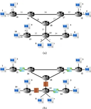
(a)
(b)
Fig. 2. (a) An example network for synthesizing security configurations and corresponding security device placements. An ID is assigned to each of the hosts, routers, and links. (b) The solution to the example problem, i.e., the placements of necessary security devices.
TABLE IV
INPUT(PARTIAL)TO THEEXAMPLE # Number of Security Devices
3 # 1 for Firewall, 2 for IPSec, and 3 for IDS, while 0 for None # Isolation Specifications (partial orders)
2 # Device, Device, Comparison (1 for=, 2 for>, and 3 for>=) 1 2 2
2 3 2
# Cost of each isolation device 20 12 15
# Number of Hosts and Routers 10 8 # Links 18 1 11 2 11 · · · ·
# Connectivity Requirements (each row for a host, which ends with 0) 3 0 # The flow from Host 1 to Host 3 must be allowed
4 0 1 2 0 2 0 3 4 0 3 4 0 1 2 0 1 0 0 1 0
# Sliders’ Values (Isolation 0-10, Usability 0-10, Cost in thousand dollars) 7.5 3 80
(i.e., the constraints) which do not satisfy. The constraints that we take as the hard clauses are connectivity requirements (CR), invariant constraints (IIC), and user-defined constraints (U IC). We take the following constraints as the assumptions:
• The network isolation constraint, i.e., I≥T hI.
• The network usability constraint, i.e., U ≥T hU.
• The deployment cost constraint, i.e., C≤T hC.
By performing a systematic analysis of the unsat-core, Con-figSynth shows the constraints that is required to be tuned or modified in order to satisfy the model. We follow Algorithm 1,
TABLE V
SELECTEDISOLATIONPATTERNS FOR THE FLOWS IN THEEXAMPLE
Destination Sources Classified according to Selected Isolation Patterns
Host Access Deny Trusted Communication Payload Inspection No Isola-tion 1 5, 6, 9 3, 4, 7, 8 − 2, 10 2 5, 6, 8, 9, 10 3, 4, 7 − 1 3 7, 8, 9, 10 2 − 1, 4, 5, 6 4 7, 8, 9, 10 1, 2 − 3, 5, 6 5 1, 2, 3, 4, 9, 10 7, 8 − 6 6 1, 2, 3, 4, 9, 10 7, 8 − 5 7 1, 2, 3, 4, 9, 10 5 − 6, 8 8 1, 2, 3, 4, 9, 10 5, 6 − 7 9 1, 2, 3, 4, 5, 6, 7, 8 − − 10 10 1, 2, 3, 4, 5, 6, 7, 8 − − 9
a simple algorithm to show all possible close solutions. In this way, ConfigSynth helps in identifying inconsistencies in the constraints and provides satisfiable choices for the constraints, which is an added support to network administrators for synthesizing the best security specifications.
C. Example
Fig. 2(a) shows a small network for which an optimal security design will be synthesized based on the given input file as shown in Table IV. In this example, the connectivity requirements are considered as the list of allowed services between different hosts. In order to keep the example simple, we consider only three primitive isolation patterns (i.e., ’access deny’, ’trusted communication’, and ’payload inspection’). We also assume a single flow type (i.e., a single service) between each pair of hosts. ConfigSynth gives a SAT result for this example. From the resultant SAT instance, we find the necessary isolation patterns along with the necessary device placements. Fig. 2(b) shows the placements of the security devices. Table V shows the isolation patterns.
V. EVALUATION
In our evaluation, we first present the analysis on the relationships between the network isolation, usability, and deployment cost. Then, we present the performance (i.e.,
scalability) analysis of the tool. We ran our experiments on different synthetic test networks.
A. Analysis of the Relationships among Isolation, Usability, and Deployment Cost Constraints
In this analysis, we ran a number of experiments considering the same network topology as it is shown in Fig. 2(a). The impact of the network usability constraint on the network isolation is shown in Fig. 3(a) under two different deployment cost constraints. We found that with the increase of the usability constraint, the maximum possible isolation reduces. However, due to the connectivity requirements, the isolation cannot be more than a particular point, though the usability constraint is very low. At the lower values of the usability constraint, the rate of the isolation decrease is less compared to the rate at the higher values of the usability constraint.
The deployment cost constraint has an impact on the isolation. Fig. 3(a) shows that in the case of the higher cost constraint (i.e., $200K), a higher isolation is achieved compared to the case of the lower cost constraint (i.e., $100K). A higher cost allows ConfigSynth to deploy more security
0 2 4 6 8 10 0 2 4 6 8 10 Isolation Usability
The relation between Isolation and Usability Cost = $100K Cost = $200K (a) 0 2 4 6 8 10 20 40 60 80 100 120 140 160 Isolation Deployment Cost
The relation between Isolation and Deployment Cost Usability = 5
Usability = 7
(b)
Fig. 3. (a) The maximum possible isolation with respect to the usability constraint considering a fixed cost constraint (i.e., $200K) and (b) the maximum possible isolation with respect to the deployment cost constraint considering a fixed usability constraint (i.e., 5).
devices, particularly IPSec devices in these experiments, which helps in increasing the isolation. We also found that with the increase of the usability constraint (i.e., from 0 to 7), the difference between the maximum possible isolation values in both of the cases reduces. At the usability value 7, we found that the isolation difference sharply increases, then slowly reduces. The reasons behind this behavior are that different security devices have different prices and different impacts on the usability (Section III). Even different deployment aspects influence the deployment cost. For example, IPSec based security usually requires deployment of two IPSec gateways close to the end hosts at the boundary of the core network, which does not let many hosts to share these devices for implementing the ’trusted communication’ isolation pattern. As a result, IPSec based security incurs a higher deployment cost compared to the firewall or IDS based security.
Fig. 3(b) shows the relationship between the isolation and the deployment cost more adequately considering two different usability constraints. We changed the cost constraint and ob-served the maximum possible isolation. Obviously, in the case of the lower usability constraint (i.e., 5), the isolation is higher compared to the case of the higher usability constraint (i.e., 7). We also found that after a certain level, it is not possible to increase the isolation despite increasing the deployment budget. This is due to the usability constraint. To increase the isolation after a certain point, it is required to use the highly scored isolation patterns (e.g., ’access deny’), which at the same time reduce the usability lower than the given limit.
B. Performance Analysis
The scalability of our proposed model is evaluated by analyzing the time and space required in synthesizing the configurations (i.e., satisfying the constraints) by varying the problem size and the constraints. The synthesis time includes the model generation time and the constraint verification time. However, the model generation time is negligible compared to that of the verification time. The problem size depends mainly on the number of flows, since the synthesis problem considers the isolation pattern for each flow. The number of flows mostly depends on the number of hosts.
Methodology: We ran ConfigSynth in a machine running
Windows 7 OS. The machine is equipped with an Intel Core i3 Processor and a 4 GB memory. We generated the test networks randomly taking hosts within the range of 50−1000 and the routers within the range of 8−20. In the test networks we
randomly choose 1−3 services (i.e., maximally 3 flows) be-tween a pair of hosts. We consider no user-defined risk-based constraints for the choice of isolation patterns (RMC). The isolation and usability constraints are chosen from normalized scales (sliders) of 0−10 (0 for no isolation/usability, while 10 for complete isolation/usability).
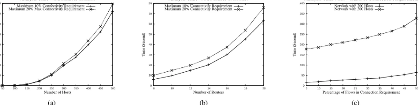
Impact of the Problem Size: Fig. 4(a) and Fig. 4(b) show the model synthesis time with respect to the problem size. In the first analysis, we considered two different scenarios. In one scenario, the volume of the connectivity requirements is 10% of all the flows possible between the hosts. In the other scenario, the percentage is 20%. In this analysis, we varied the problem size with respect to the number of hosts and the corresponding results are shown in Fig. 4(a). We observed that the analysis time increases rapidly with the number of hosts. This is due to the reason that the problem size depends on the number of possible flows in the network. The number of flows isO(N2), where N is the number of hosts and the number of services is constant. The volume of the connectivity requirements also increases with the increase in the number of flows. As a result, the model size increases, which requires the verification of more constraints. All of these increase the running time overO(N2). In the second analysis, we varied the core network by changing the number of routers in two different connectivity requirements. The results are presented in Fig. 4(b). In this case, since the number of hosts in the network remains the same, there is no increase in the number of flows. However, due to the increase in the number of routers, the core network becomes larger, where the hosts are more distributed and more links are turned out as the candidates for security device placements. As a result, more search is required to find a satisfiable model, which increases the synthesis time. We observed quadratic increase in the synthesis time. We also analyzed the impact of the volume of the connectivity requirements (i.e., the percentage of all flows that are in the connectivity requirements) on the synthesis time. The results are presented in Fig. 4(c). Though the number of total flows in the network remains unchanged in this case, the increase in the number of connectivity requirements adds more constraints which decreases the possible options for a satisfiable model. Hence, the synthesis time increases. Impact of the Tight and Relaxed Constraints:We analyzed the impact of the tight or relaxed constraints on the model synthesis time. Tightening (relaxing) the network isolation or usability constraint means to increase (decrease) the associated
0 100 200 300 400 500 600 700 800 50 100 150 200 250 300 350 400 450 500 Time (Second) Number of Hosts
Analysis Time w.r.t. Number of Hosts
Maximum 10% Connectivity Requirement Maximum 20% Max Connectivity Requirement
(a) 0 10 20 30 40 50 60 70 80 8 10 12 14 16 18 20 Time (Second) Number of Routers
Analysis Time w.r.t. Number of Routers
Maximum 10% Connectivity Requirement Maximum 20% Connectivity Requirement
(b) 0 50 100 150 200 250 300 350 400 5 10 15 20 25 30 35 40 45 50 Time (Second)
Percentage of Flows in Connection Requirement
Analysis Time w.r.t. Volume of Connection Requirement
Network with 200 Hosts Network with 300 Hosts
(c)
Fig. 4. The model synthesis time w.r.t. (a) the number of hosts, (b) the number of routers, and (c) the volume of the connectivity requirements.
50 100 150 200 250 300 350 400 450 500 550 1 1.5 2 2.5 3 3.5 4 4.5 5 Time (Second) Isolation Constraint
Analysis Time w.r.t. Isolation Constraint
Usability Constraint = 3 Usability Constraint = 5 (a) 100 200 300 400 500 600 700 800 1000 1200 1400 1600 1800 2000 Time (Second)
Deployment Cost Constraint
Analysis Time w.r.t. Deployment Cost Constraint
Usability Constraint = 3 Usability Constraint = 5 (b) 0 50 100 150 200 250 300 350 400 100 150 200 250 300 350 400 Time (Second) Number of Hosts
Analysis Time in Unsat Cases
Unsatisfiable Case Satisfiable Case
(c)
Fig. 5. (a) The impact of the isolation constraint on the model synthesis time, (b) the impact of the deployment cost constraint on the model synthesis time, and (c) the comparison between the satisfiable and unsatisfiable cases w.r.t. the model synthesis time.
constraint value. On the other hand, tightening (relaxing) the deployment cost constraint means to decrease (increase) the constraint value. The analysis results are shown in Fig. 5(a) and Fig. 5(b) varying the isolation constraint and the de-ployment cost constraint, respectively. In these analyses, we considered a fixed number of hosts (300) and a fixed volume of connectivity requirements (10% of all flows) in two different network usability constraints (3 and 5 in a scale of 10). We observed that the execution time increases significantly with the increase of the network isolation constraint (see Fig. 5(a)). This is due to the reason that increasing the isolation constraint reduces the number of possible solutions to the model with respect to a particular usability constraint and a specific deployment budget. As a result, usually more search (i.e., a longer time) is required to find a solution. After a certain value of the isolation constraint (i.e., 3-4), a small increase in the constraint increases the synthesis time sharply. We observed almost similar behavior in the case of the deployment cost constraint (see Fig. 5(b)). In this case, the higher is the budget, the more satisfiable options are available. Hence, the synthesis time decreases with the increase of the budget. We observed that after a certain increase in the budget ($1500K), the synthesis time does not decrease further. Because, the number of potential satisfiable models does not increase any more despite increasing the budget.
Performance in the Unsatisfied Cases: In the cases of very tight constraints (e.g., very high values for isolation and usabil-ity constraint or low values for the cost constraint), there may not be any satisfiable model. In these cases, the SMT solver takes slightly longer time to give the unsatisfiable (UNSAT) results compared to the time required in the satisfiable cases.
TABLE VI
THE MEMORY REQUIREMENT(MB)W.R.T.PROBLEM SIZE
Hosts Scenario 1 Scenario 2
200 6.71 6.59
400 30.48 41.72
600 113.99 160.70
800 376.21 532.89
1000 818.92 1158.54
Because, in an unsatisfiable case, the SMT solver requires verifying all possible ways to conclude that there is no solution satisfying all of the given constraints. Fig. 5(c) shows the comparison between the satisfiable and unsatisfiable cases with respect to the synthesis time.
Space Requirement:The space (memory) requirement of our model based on the SMT solver [2] is evaluated by changing the number of hosts. The evaluation is done considering the memory required for modeling the synthesis problem. The memory requirement is the sum of the memory for modeling the system parameters and that for modeling the constraints. The analysis results are shown in Table VI in two different scenarios of the network isolation constraint. In the first scenario, the isolation constraint is 3 (in a scale of 10), while in the second scenario, this is 5. We observed that the memory requirement increases quadratically (O(N2)) with the increase in the number of hosts. The table shows that the memory requirement in the second scenario is larger than the memory requirement in the first scenario. If the isolation constraint is high, the solver requires searching more options for a satisfiable solution, which incurs more space.
Discussion on Performance Analysis:Our evaluation results show that the time and memory requirements of ConfigSynth increases quadratically with the problem size. However, Con-figSynth can solve a synthesis problem with 500 hosts (i.e.,
several thousands of flows) within 800 seconds consuming 100MB memory only. Apparently, it may seem that this num-ber of hosts is small comparing to large enterprise networks. However, in most of the large networks, usually many of the hosts exhibit similar properties. They are running the same OS, services, and even operated by the same level of users (e.g., a student lab in a university or a customer service center in an organization). They usually reside under the same subnet. The security configuration for such a group is expected to be the same. Hence, this group can easily be assumed as a single host. Moreover, in an enterprise network the overall number of services running on the hosts are also limited. Therefore, our model is adequately efficient for an enterprise network.
VI. RELATEDWORK
In this section, we study researches that focus on either security policy management or security configuration harden-ing. Throughout the last decade, the security policy miscon-figuration have been studied extensively in [3], [4], [5], [6], [7], [8]. In these works, the formal definition of configuration anomalies and safe deployment of single or multiple security devices, mainly firewalls, have been presented and algorithms were proposed to discover configuration inconsistency. These works follow the traditional bottom-up approach of analyzing existing security policies, which cannot be used to automati-cally synthesize policies based on business requirements.
Several researches have been done on attack graph based security configuration analysis. In [9], the author proposes a technique to place intrusion detection system (IDS) sensors and prioritize IDS alarms using attack graph analysis. The IDS sensors are placed to cover all these paths. In [10], the authors model the problem of selecting a set of security hardening measures to minimize the residual damages in a predefined attack graph within a certain budget. Few works have proposed to find optimal deployment of security devices using attack graphs in order to block all attack scenarios [11], [12]. How-ever, these works cannot find optimal security configurations as well as the automated security device placements within the deployment budget and usability constraint.
The research on the security design synthesis is in a pre-mature stage. ConfigAssure is a requirement solver presented in [13]. The tool takes security requirements and configuration variables as inputs and produces the values of the configuration variables as outputs that make the requirements true. Confi-gAssure requires complete and well defined properties and it can not reason about the optimal configuration based on isolation, usability and deployment cost. In the works [14], [15], the authors presented procedural approaches of gen-erating firewall configurations. In [15] they also considered the device deployment cost. However, these works only de-scribe generation of firewall policy configurations and do not consider different isolation measures (i.e.. firewalls, IPSec, IDS, etc.) in the context of security requirements, usability satisfaction, and deployment cost constraints. In addition, these works cannot do the optimal placements of security devices in the network. Even, the model presented in [15] does not relate
security device placements (according to the topology) with the computation of residual risks. Hence, none of the above works generates a security design architecture considering the security requirements and business constraints exploring various security design alternatives in determining satisfiable security configurations, which is the major thrust of this paper.
VII. CONCLUSION
Although security architecture design usually follows well-known security principles, it is still performed in an ad-hoc manner. In this paper, we present an automated framework, ConfigSynth, for synthesizing correct and cost-effective net-work security configurations. It formally models the netnet-work topology, security requirements in terms of isolation, and the organizational business constraints in terms of usability and deployment cost, along with different invariant and user-defined constraints. Then, the framework formalizes the se-curity design synthesis problem as the conjunction of all the requirements and constraints. Finally, it solves the problem us-ing an efficient SMT solver that results in an optimal network security design along with optimal placements of security devices. We have evaluated ConfigSynth tool in different test networks by varying the problem size and the number of constraints. We find that ConfigSynth generates an optimal security design within 800 seconds for a problem with 500 hosts. In the future, we would like to extend our model in order to incorporate the host and application level isolation patterns along with various design constraints.
REFERENCES
[1] L. de Moura and N. Bjørner. Satisfiability modulo theories: An appetizer. InBrazilian Symposium on Formal Methods, 2009.
[2] L. de Moura and N. Bjrner. Z3: An efficient smt solver. InConf. on Tools and Algo. for the Construction and Analysis of Systems, 2008. [3] E. Al-Shaer and H. Hamed. Discovery of policy anomalies in distributed
firewalls. InIEEE INFOCOM, 2004.
[4] H. Hamed, E. Al-Shaer, and Will Marrero. Modeling and verification of ipsec and vpn security policies. InIEEE ICNP, 2005.
[5] L. Yuan et al. Fireman: A frameworkkit for firewall modeling and analysis. InIEEE Symposium on Security and Privacy, 2006. [6] Charles C. Zhang, Marianne Winslett, and Carl A. Gunter. On the safety
and efficiency of firewall policy deployment. InIEEE Symposium on Security and Privacy, 2007.
[7] E. Al-Shaer et al. Network security configuration in a box: End-to-end security configuration verification. InIEEE ICNP, 2009.
[8] P. Bera, S. Ghosh, and P. Dasgupta. Policy based security analysis in enterprise networks -a formal approach. InIEEE TNSM, 2010. [9] Steven Noel and Sushil Jajodia. Attack graphs for sensor placement, alert
prioritization, and attack response. In Cyberspace Research Workshop of Air Force Cyberspace Symposium, 2007.
[10] R. Dewri et al. Optimal security hardening using multi-objective optimization on attack tree models of networks. InACM CCS, 2007. [11] J. Homer and X. Ou. Sat-solving approaches to context-aware enterprise
network security management. InIEEE JSAC Special Issue on Network Infrastructure Configuration, 2011.
[12] I. Kotenko and M. Stepashkin. Attack graph based evaluation of network security. InInternational Conference on Communications and Multimedia Security, 2006.
[13] S. Narain, G. Levin, V. Kaul, and S. Malik. Declarative infrastructure configuration synthesis and debugging. InJNSM, 2008.
[14] et al. B. Zhang. Specifications of a high-level conflict-free firewall policy language for multi-domain networks. InACM SACMAT, 2007. [15] B. Zhang and E. Al-Shaer. Synthesizing distributed firewall