The application of multi-agent systems for STEP-NC computer
aided process planning of prismatic components
A. Nassehi
a,*, S.T. Newman
b, R.D. Allen
a aAdvanced Manufacturing Systems and Technology Centre, Wolfson School of Mechanical and Manufacturing Engineering, Loughborough University, Loughborough LE11 3TU, UK
bDepartment of Mechanical Engineering, University of Bath, Bath BA2 7AY, UK
Received 9 February 2005; accepted 1 June 2005 Available online 15 August 2005
Abstract
For many years, manufacturing firms have been seeking more efficient ways of manufacturing components with CNC machines. The emerging standards ISO 14649 and ISO 10303 (AP238) present an opportunity to revolutionize the way CNC machines are traditionally programmed. These standards better known as STEP-NC replace the traditional tool movement description languages with hierarchical data structures that allow a new breed of CNC to store part geometry together with the working steps of the operations required to manufacture the part. STEP-NC provides the ability to store and utilise high level and detailed information from the CAD system to the intelligent STEP compliant CNC controller. With the advent of STEP-NC, computer aided process planning has become a critical link in the CAx process chain with the major requirement to generate interoperable process plans. The authors therefore believe it is necessary to redefine CAPP to reflect the change from the traditional tool movement based programming to STEP-NC based programming.
This paper examines the application of distributed artificial intelligence methods, namely collaborative multi-agent systems in designing an object-oriented process planning system for prismatic components in a STEP-NC compliant environment. The specification and design of a prototype system entitled the Multi-Agent System for Computer Aided Process Planning (MASCAPP) is outlined. Two test components have been designed, process planned, simulated on the machine controller and finally machined, to demonstrate the capabilities of the system and illustrate the activities required to implement STEP compliant manufacturing.
q2005 Elsevier Ltd. All rights reserved. Keywords:Multi-agent systems; STEP-NC; CAPP
1. Introduction
Since the invention of CNC machines in the 1950s, enormous advances have been made in the machines’ capabilities, precision and speed. Today 5-Axis machining centres are able to accurately manufacture complex parts in a single set-up for a fraction of the time that would have been needed, were the parts to be manufactured using the traditional NC machines. Despite these advances in the machining centres’ hardware and technology, the program-ming language used to program them, is essentially unchanged from that of the 1960s. These programming languages based on G&M codes formalised in the ISO 6983
standard[1]are used to define tool movements and simple switching operations for the low-level programming of CNC controllers.
An international effort is now being made towards development of a new data model and a new approach to programming of CNC machines that can open the path for exploiting their advanced capabilities with greater ease and efficiency. This framework is materialising in the form of standards collectively known as STEP-NC. STEP-NC replaces the traditional G&M codes used to program machines with a hierarchical data structure that contains product geometry and working steps required for part manufacture. While the ISO 6983 compliant programs contained information onhowto build a part, the contents of the new data structure indicatewhatneeds to be done for the
product to be manufactured [2]. Within the STEP-NC
standard[3], the main manufacturing workplan for each part is comprised of several working steps. Each working step
www.elsevier.com/locate/ijmactool
0890-6955/$ - see front matterq2005 Elsevier Ltd. All rights reserved.
doi:10.1016/j.ijmachtools.2005.06.005 * Corresponding author.
can either be a manufacturing working-step or a combi-nation of other working-steps. To achieve maximum performance in STEP-NC manufacturing, it is necessary to define the working-steps existing within the hierarchical data model in the optimum order.
Through a STEP compliant[4]process planning system, a major function of the system is to detect conflicts and efficiently plan the interactions between the working steps to achieve the optimum order. Thus it is desirable to have an automated system capable of planning the manufacturing process of each part optimally.
While many techniques can be used for determining the optimum order of objects, the developments in distributed artificial intelligence[5,6]and intelligent agents[7], make them a potential candidate for this purpose. Multi-agent systems perform well when it is possible to break the main problem down into a set of connected less complex problems and as it happens process planning can be treated as such a problem.
Employing multi-agent systems on complex data sets requires a robust and efficient information backbone for achieving reasonable performance. Information storage techniques are numerous and a careful study is required to determine which method is more suitable for the purpose of developing the automated agent-based process planning system. This paper recognises and extends the earlier research on agent-based process planning by Allen et al.[8] by employing simpler and fewer agents, an object oriented environment, advanced feature interaction algorithms and an interface to Siemens STEP-NC interpreter using STEP 10303-21 files[9].
The paper investigates the application of multi-agent systems in STEP-NC compliant process planning. First a brief review on the agent technology and multi-agent systems and their application in manufacturing is presented. A prototype process planning system is then created using the Java programming language. To develop this system, a robust information backbone is a necessity. A short study was made on the different information handling methods and an object-oriented database system was chosen to serve as the data provider. To limit the scope of the research a limited set of components were needed and since definition of features of prismatic components is straightforward, this type of component is selected. The developed system, entitled Multi-Agent System for Computer Aided Process Planning (MASCAPP), focuses on two of the many geometric features (i.e. general closed pocket and round hole) defined in ISO14649 to illustrate the functionality of multi-agent systems. Sample parts are designed, process planned and exported as STEP-NC compliant files within the system to demonstrate its capabilities. The exported STEP-NC files are then interpreted and
simulated on a SIEMENS controller with SHOPMILLe
OPEN 6.03 software.
2. Review of STEP-NC technology and multi-agent technology
The MASCAPP system proposed in this paper relies on three major elements, namely:
† CAPP within STEP-NC manufacturing environment;
† Multi-agent systems;
† STEP-NC compliant information modelling tools. It is therefore necessary to define process planning in the STEP-NC environment and specify what it entails, introduce intelligent agents and multi-agent systems based on the collaboration of a group of software agents and finally explore different strategies for STEP-NC information modelling to identify the best potential method of information handling to support process planning.
2.1. CAPP within STEP-NC manufacturing environment
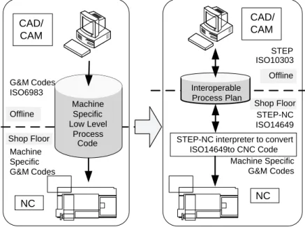
In ISO 6983, the current standard for numerical control, tool motions are defined using G codes and simple switching instructions are issued by using M codes[1]. This method of machine programming, results in loss of product infor-mation along the manufacturing process chain. As the product geometry designed in CAD software is passed on to the CAPP and CAM software, toolpaths and switching instructions specific to an individual machine are generated to optimize the manufacturing effort.
The output from the CAM system consists of only low level description of toolpaths with all the geometric features and tolerances discarded. There are a number of inherent problems with this traditional process chain; the most important of which is perhaps the one-way flow of information. Here, the information generated in the CAD system is passed on to the CAPP system and then onto the CAM system and finally to the machine controller for manufacturing. As a result of this uni-directional infor-mation flow, changes made in the final part program generated by the CAM system on the shop floor are not reflected in the product model existing in the CAD/CAM systems.
STEP-NC allows bidirectional flow of information[10]. Since features and part geometry are maintained throughout the manufacturing process, the changes on the shop floor are
immediately reflected in the CAD/CAM models. Fig. 1
shows this fundamental difference.
With ISO 6983 (G&M code) programming, process planning determines the order in which toolpath instruction chains should be executed. In STEP-NC, process planning is used to determine the order in which different features or multiple features should be manufactured. In addition a major and critical requirement is that a process planning system in the STEP-NC framework should be able to detect conflicts and interactions between working steps required
for manufacturing features and resolve the situation as effectively as possible.
To limit the scope of the research, a subset of the STEP-NC features for prismatic components have been chosen. The generic closed pocket and the straight drilled and reamed round hole are the two feature types represented in MASCAPP, the former providing the capability to define a wide variety of pocket-type features such as rectangular pockets or triangular pockets, etc. and the latter providing an additional type of feature for interaction and conflict detection algorithms.
Two types of feature interactions are considered in the system, overlaps and enclosures. Whenever a feature’s geometrical boundary, intersects with that of another feature, an overlap occurs. Two examples of overlaps can be seen inFig. 2.
An enclosure occurs when one feature’s boundaries encompass another feature’s boundaries completely in the first two axis of the coordinate system. Fig. 3 shows an example of feature enclosures.
These interactions can be modelled in STEP-NC using the compound feature representation[11].
To reach an effective process plan, MASCAPP organizes the main workplan of the component in a sequence of
operations to be performed on non-conflicting, autonomous features. Interacting features are detected and combined into compound features.
2.2. Multi-agent systems
The science of artificial intelligence is almost 40 years old. It started in a conference held in Dartmouth in 1958 [12]. Distributed artificial intelligence, a field as old as artificial intelligence itself is concerned with collaborative solution of global problems by a distributed group of entities [5]. Intelligent agent systems and in particular systems using more than one agent (multi-agent systems) are realizations of such a concept[7].
In multi-agent systems, small autonomous programs known as agents, undertake a specific task and try to accomplish it by interacting with the environment and the other agents. When designed appropriately, success of each and every agent will contribute to the solution of the global problem and when all agents have completed their goals, the main problem is solved.
It is not very easy to provide a single definition for intelligent agents and over the years several different definitions have been provided: Russel and Norvig [13]
Fig. 3. Feature enclosure. Shop Floor G&M Codes ISO6983 STEP-NC ISO14649 Offline CAD/ CAM CAD/ CAM NC NC Machine Specific G&M Codes Machine Specific Low Level Process Code Interoperable Process Plan
STEP-NC interpreter to convert ISO14649to CNC Code Offline Machine Specific G&M Codes Shop Floor STEP ISO10303
Fig. 1. Bi-directional information flow in STEP-NC.
define an agent as “anything that can be viewed as perceiving its environment through sensors and acting upon that environment through effectors”, while Woolridge [7]defines an agent as “a computer system that is situated in some environment and that is capable of autonomous action in this environment in order to meet its design objectives”. Franklin and Graesser [14] propose this definition: “An autonomous agent is a system situated within and a part of
an environment that senses that environment and acts on it, over time, in pursuit of its own agenda and so as to effect what is senses in the future”.
Combining these definitions, several properties can be attributed to intelligent agents. These properties are shown inTable 1.
Franklin and Graesser [14] proposed a (limited)
taxonomy of agents, and Nwana [15] proposed a classifi-cation of software agents distinguishing: collaborative agents; interface agents; mobile agents; information agents; reactive agents; hybrid agents; heterogeneous agent systems; and smart agents. These classifications together with their description can be seen inTable 2.
In the recent years, the trend for using multi-agent systems has increased substantially with a number of projects in progress to apply the multi-agent techniques to different aspects of manufacturing.
Shen and Norrie[16]undertook an extensive research on the ongoing projects in different fields. Most projects are concerned with:
(i) Enterprise integration and supply chain manage-ment: Where every system in the enterprise has Table 1
Properties of intelligent agents (adapted from Franklin and Graesser[14])
Property Definition
Reactive Shows timely responses to the changes in the environment
Autonomous Has control over its actions Goal-oriented Pursues a certain goal and does not
simply react to the environment Temporally
continuous
The running process is continuous Communicative Can communicate with other agents Learning Changes behaviour by previous experience Mobile Can move from one environment to
another similar environment Flexible The actions are not pre-scripted
Character Has a believable ‘personality’ and emotion state
Table 2
Agent typology (adapted from[15])
Software agent type Representation Description
Collaborative agents Autonomy and cooperation are the main characteristics. Learning
might be present but is not the main emphasis
Interface agents Learning and autonomy are the main focuses
Mobile agents Agents capable of migrating to different parts of a computer network
to achieve their function
Information agents Manage and gather information from many data sources
Reactive agents Agents that only respond to a specific stimulus and are not generally
aware of their environment
Hybrid agents Agents that have a combination of above mentioned abilities
Heterogeneous agents Integrated set of different kinds of agents that can function together.
Some agents might be hybrid agents
Smart agents Nwana[15]believes that these agents are just aspiration of
access to relevant information to its task stored in all systems of the enterprise. Intelligent agents provide means of information transfer while controlling the security and safety issues for the information. They ensure that when a certain piece of software is entitled to receive a certain piece of information, the data is delivered safely, accurately and in a timely fashion. It should be noted that the same concept applies to supply chain management where agents transfer the required information between different links in the chain[17].
(ii) Manufacturing planning, scheduling and control: Manufacturing scheduling is perhaps the most researched field in relation to agent based systems. As online planning and scheduling is often very suitable for applying a multi-agent approach. Each agent representing a certain job to be scheduled competes for the best position possible and as a result, the scheduling is achieved in a near optimal fashion[18]
(iii) Holonic manufacturing systems: The HMS concept was first proposed in 1994 by the HMS consortium as a test case under the international Intelligent Manufacturing Systems (IMS) research program [19]. A holon is defined as “an autonomous and cooperative building block of a manufacturing system for transforming, transporting, storing and/or validating information and physical objects” [20]. As a result in an HMS all the entities in the manufacturing system (Product, Parts, AGVs, machines, etc.) have autonomous yet cooperative properties.
In addition, there is ongoing agent-based research on general process planning in manufacturing following the MAPP (Matrix Architecture for Process Planning) concept proposed by Hayes[21]. Based on this research, Kornienko et al. [22] have studied flexible manufacturing process planning based on multi-agents. In a later paper, Kornienko et al. [23] propose a multi-agent repairer of damaged process plans in a manufacturing environment.
The authors believe that CNC Process planning, and in particular STEP-NC process planning are currently exciting fields of research for agent-based systems as most research seems to be focused on scheduling and supply chains. Process planning and manufacturing strategy planning systems are potentially suitable for the multi-agent approach due to their distributed knowledge and intelligence requirements. It is conceivable that by incorporating artificial intelligence in the form of multi-agent systems in adaptive interoperable manufacturing systems, it would be possible to allow the system to perform a wide range of tasks automatically. These tasks which can include selection of CNC machines and cutting tools for a particular part, selection of the effective manufacturing process for a product according to the production requirements or
suggestions for changes in a product’s design which would allow a more economical approach to its production.
2.3. STEP-NC compliant information modelling methods
To build the necessary STEP-NC compliant information model two types of data storage structures can be used; files and databases. Files represent a quick, efficient way of storing information. They do not however, provide any management capabilities and it is up to the software using the information to manage the data appropriately. Database systems exist in different reincarnations but in general offer data management facilities as well as information storage capabilities.
The simplest way of constructing the model would be to use flat files: files which contain no meta-data about the information stored sequentially within them. Tagged files which add meta-data to flat files represent another possibility. Currently, the most common format for tagged files is extensible markup language [24], better known as XML [25]. As the major contender for industry standard data transport format, XML can be read and written by most
software packages and thus provides excellent
compatibility.
Database management systems, in addition to storing the data, manage the meta-data and provide means for accessing required information rapidly through the use of queries. Currently three types of databases are commonly used in software development: relational databases systems, object-relational database systems and object-oriented database systems.
Relational databases—doubtlessly the most popular form of data storage in today’s computer applications—use key fields to relate discrete items of data together; hence the name relational databases[26]. Meta-data is defined in the creation of the data structures; tables, records and fields and is stored together with the data by the database management system.
Object orientation provides a natural way of modelling the physical world into software. Advocates of object-oriented approach feel that the technology offers many advantages over the traditional models[27]. Object-oriented database systems, store objects instead of relational and tabular data and thus contain methods or functions as well as data about logical entities. UML [28] and OMT [29] are often cited as the most popular object oriented modelling tools.
Object-relational databases are hybrid systems that offer an object-oriented view of the information stored in relational databases.
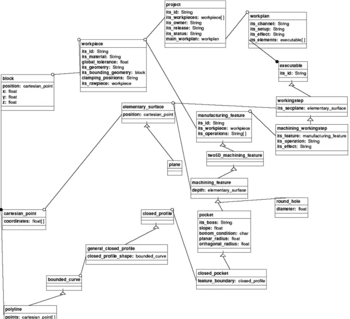
On considering the hierarchical nature of STEP-NC constructs and existence of concepts such as inheritance (i.e. closed_pocket is a subtype of machining_feature)[11], the authors believe that object oriented modelling tools provide the most effective framework for constructing an infor-mation model for MASCAPP. Due to the extra complexity
presented by the Object-relational databases, ObjectStore 6.0, an object oriented database system has been used to construct MASCAPP’s STEP-NC compliant information model[30].
3. Multi-agent system for computer aided process planning (MASCAPP)
To investigate the effectiveness of multi-agent systems for developing a STEP-NC compliant process planning
system, a prototype system (MASCAPP) has been realised based on commercial software development tools. The main research goal was to investigate the efficiency of using multi-agent systems in handling process planning problems and explore the possibilities for introducing multi-agent systems in STEP-NC manufacturing. The design framework for MASCAPP is illustrated through an IDEF0 vision of the system inFig. 4.
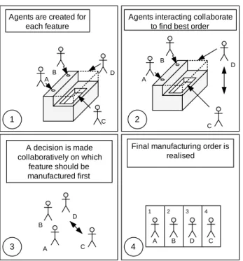
The MASCAPP system employs a collaborative multi-agent system where each individual multi-agent is charged with the responsibility of identifying manufacturing require-ments for an individual manufacturing feature. The agents then collaborate with the help of a facilitator agent to determine the interactions between features. An overall presentation of the MASCAPP system at work can be seen in Fig. 5. This illustrates the creation of agents and their interactions based on the features they are assigned to and the collaboration leading to the decision regarding the manufacturing order of features.
Fig. 6 depicts the STEP-NC manufacturing chain
which starts with the definition of the feature based product geometry in MASCAPP. An ISO 10303 Part 21 physical file is then generated by MASCAPP. This file is processed by the Siemens STEP-NC interpreter and is translated into a Siemens proprietary format.MPF file. The generated file can then be directly machined on any CNC workstation equipped with a Siemens controller and ShopMill software.
3.1. Data model definitions
The information model for MASCAPP has been designed with STEP-NC compliancy in mind and thrives to provide capabilities that can be expanded to accommo-date the complete hierarchical data structure of ISO14649 as defined in the standard. Considering the advantages and shortfalls of methods investigated in Section 2.3, an object-oriented database system has been selected to provide information storage capabilities.
The STEP-NC schema [11] is a fairly complex data
structure and a subset of the features had to be chosen for the prototype system development. As prismatic components and related features are well-defined within the STEP-NC framework, the process-planning system has been designed to handle prismatic components.
1 2 3 4
B
A D C
Final manufacturing order is realised A decision is made collaboratively on which feature should be manufactured first C D B A A B C D Agents interacting collaborate
to find best order
A B
C D Agents are created for
each feature
2 1
3 4
Fig. 5. MASCAPP operational process fundamentals.
Fig. 6. MASCAPP design to manufacture chain.
A0 Create ISO 14649
Process Plan
MASCAPP Feature based geometry
model ISO 14649 Process Plan Manufacturing Technology Data ISO 14649 Data Model Manufacturing Resource Data ISO 10303-21 Standard
An OMT representation of the data model used in MASCAPP development can be seen inFig. 7. The objects have been defined with attributes similar to those defined in the EXPRESS schema for STEP-NC 0 to ensure compliancy. It should be noted that some attributes have been modified or discarded with regards to the scope of the research.
This model was constructed using the database design tools provided by ObjectStore 6.0 object oriented database management system. Using the translation facilities provided by the ObjectStore software suite, a JAVA interface to the data model was generated. This interface together with the generated persistent objects provide the information repository framework for the MASCAPP system.
3.2. MASCAPP agent definitions
The MASCAPP system employs two different kinds of agents. An intelligent agent from the classFeature_Agentis charged with the responsibility for each feature. One
Police_Agentwill act as the facilitator between the agents. Both of these agents are collaborative agents communicat-ing mainly with each other.
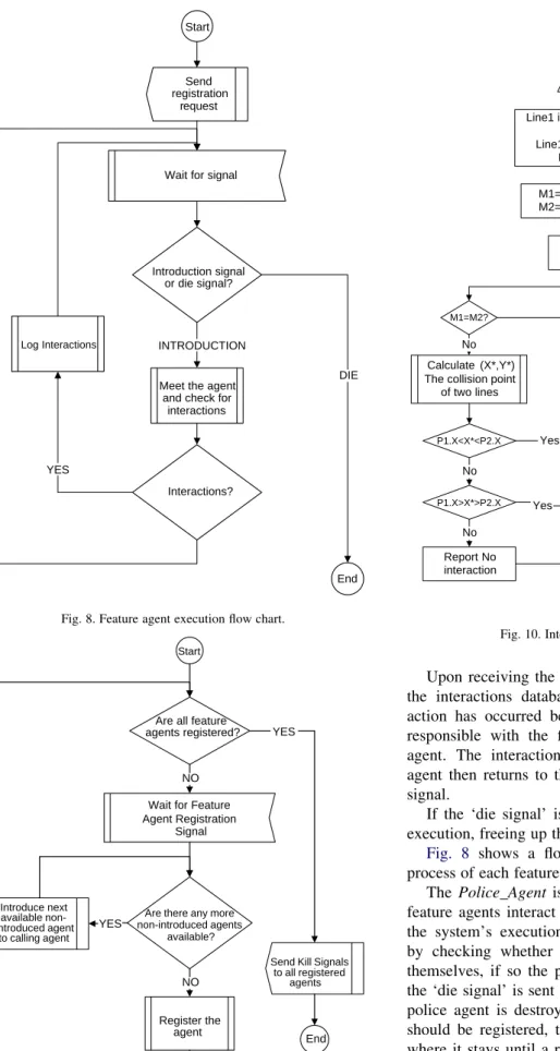
A feature agent’s execution is started by the agent sending a signal to the police agent requesting registration. The agent then waits to receive a signal. There are two possible signals the agent might receive, an ‘introduction signal’, when the agent should interact with another and a ‘die signal’ when the overall program is finished and all entities should be destroyed.
Upon receiving the ‘introduction signal’ the agent uses the interactions database to ascertain whether an inter-action has occurred between the feature for which it is responsible with the feature handled by the introduced agent. The interactions are logged in the system. The agent then returns to the wait state and waits for another signal.
If the ‘die signal’ is received by the agent, it halts its execution, freeing up the computer memory it occupied.
Fig. 8 shows a flowchart representing the execution process of each feature agent.
The Police_Agentis a facilitator agent that ensures all feature agents interact appropriately, during the course of the system’s execution process. The Police_Agent starts by checking whether all feature agents have registered themselves, if so the program has finished execution and the ‘die signal’ is sent to all feature agents; just before the police agent is destroyed. If there are more features that should be registered, the police agent enters a wait state where it stays until a registration request is received from a feature agent. Upon receipt of such a signal, the police agent sends introduction signals to the registering agent
Wait for signal Start
Introduction signal or die signal?
YES
DIE Meet the agent
and check for interactions INTRODUCTION End Send registration request Log Interactions Interactions? NO
Fig. 8. Feature agent execution flow chart.
Wait for Feature Agent Registration
Signal Start
Are all feature agents registered?
Introduce next available non-introduced agent
to calling agent
Are there any more non-introduced agents
available? NO
YES
YES
Send Kill Signals to all registered agents Register the agent NO End
Fig. 9. Police agent execution flowchart.
Start
Get Points P1..P4
Line1 is defined by P1 and P2 and Line2 by P3 and P4 Line1's equation is Y=m1X+h1
Line2's is Y=m2X+h2 M1=(P2.Y-P1.Y)/(P2.X-P1.X) M2=(P4.Y-P3.Y)/(P4.X-P3.X) M1=M2? H1=P1.Y-M1*(P1.X) H2=P3.Y-M2*(P3.X) H1=H2? Calculate (X*,Y*) The collision point
of two lines P1.X<X*<P2.X P1.X>X*>P2.X End Report Collision Report No interaction Yes No No No Yes Yes Report The Same Line Yes Report Parallel Lines No
with the details of all previously registered agents. When the registering agent has been introduced to all previous agents, it is itself registered. The police agent then checks whether it should wait for more features and again enters the wait state. Fig. 9 shows a flow chart presenting the execution flow of the police agent.
3.3. Feature interaction detection algorithms
At the heart of the MASCAPP system lies a compilation of classic interaction detection algorithms. These algorithms determine whether features represented
by feature agents have interactions. A number of mathematical methods are used for determination of feature interactions.
A bounding box method is used to quickly determine if features are far apart and thus have no interactions and can be considered autonomous. In this method the rectangles enclosing two features are studied to determine whether an intersection on the edges is possible.
When an interaction is not rejected by the bounding box method, a line intersection algorithm is used.
This algorithm decides whether two line segments intersect. Let us assume line segment one and two are
Start
Get Feature X with points (1..m-1) and Y with points (1..n-1)
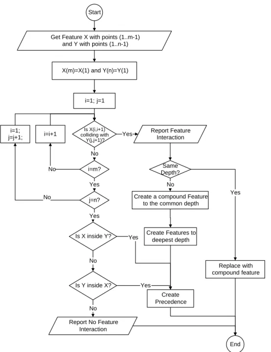
i=1; j=1 Is X(i,i+1) colliding with Y(j,j+1)? i=m? j=n? Is X inside Y? Is Y inside X? Report No Feature Interaction No Yes Yes No No Report Feature Interaction Same Depth? Replace with compound feature End Yes Yes Create a compound Feature
to the common depth
Create Features to deepest depth Create Precedence No No i=i+1 X(m)=X(1) and Y(n)=Y(1) i=1; j=j+1; No Yes Yes
defined as: L1 from (X11,Y11) to (X12,Y12), L2 from (X21,Y21)
to (X22,Y22), whereX11!X12andX21!X22.
First the equation for each line is found by:
m1Z ðY12KY11Þ ðX12KX11Þ (1) h1ZY12Km1X12 (2) And similarly: m2ZðY22KY21Þ ðX22KX21Þ (3) h2ZY22Km2X22 (4)
Now the two line equations will be solved simultaneously:
YZm1XCh1 YZm2XCh2 0 Km1X CY Zh1 Km2XCYZh2 ( ( (5) The solution forX* andY* would be:
XZ h1 1 h2 1 Km1 1 Km2 1 Z ðh1Kh2Þ ðm2Km1Þ YZ Km1 h1 Km2 h2 Km1 1 Km2 1 Z ðh1m2Kh2m1Þ ðm2Km1Þ (6)
Now if X11!X*!X12 and X21!X*!X22 the point
(X*,Y*) is the intersection of the two line segments, otherwise there is no intersection. It should be noted that when one or both lines are vertical, a slightly different approach is taken. Fig. 10 shows how this algorithm is executed within the program.
The feature interaction algorithm then uses the line intersection algorithm outlined above to try and detect overlap interactions between pocket features. The flow chart for the algorithm can be seen inFig. 11.
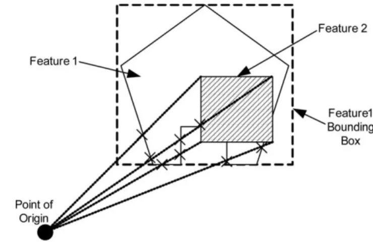
Another algorithm determines if a feature is enclosed by another feature. It is based on a simpler algorithm for determining if a point is inside a feature. To check this, a point outside the feature is chosen as the point of origin. To find this point first the bounding box of the feature is found. This is achieved by finding minimum and maximumXandY
coordinates of the feature. The point is then chosen outside this rectangle.
A line is then drawn from the point of origin to the point whose status is required. If the line drawn intersects with the feature an odd number of times (This can be determined by a slight alteration to the second algorithm mentioned above.), the point is inside the feature, otherwise the point is outside the feature.
For one feature to be completely enclosed by another one, all its vertices should be inside the second feature and no vertices from the second feature should be inside the first. Fig. 12 shows a diagram for this algorithm. Fig. 13 shows the flow chart for the algorithm as implemented in the program.
While the algorithms used in MASCAPP are capable of determining overlaps and enclosures for features in prismatic parts, they are by no means complete. These algorithms however, can be extended to detect overlaps in
Fig. 12. Diagram for enclosure detection algorithm.
Start
Find the Bounding Box for Feature1
Assume Point X’ outside the Bounding Box
Test the line passing through X’ and each of Feature2's vertices for interaction with Feature1's Edges
Count The number of Collisions If the line collides with an odd number of edges the
point from Feature 2 is inside Feature 1
Are all vertices of feature2 inside feature1?
Report Feature2 Inside Feature1
Report Feature2 Not Inside Feature1
End YES
NO
three dimensions and therefore be utilised in all feature based process planning systems.
3.4. STEP-NC post-processor
After ordering the objects representing features in the MASCAPP system, it is necessary to post-process the information contained in them to generate an ISO10303-21 compliant STEP-NC file. The post-processor in MASCAPP first orders all the objects within the system workspace in a list. Each object in the list has an index number and can be accessed directly by this number. The index number for each object is analogous with the line number for the equivalent STEP-NC entity in the ISO10303-21 file. After storing the objects in the list,
the output file creation phase starts where the object relations are replaced by index numbers. The file generation phase finishes when the generated list of indexes is written to a text file using the ISO10303-21 convention with hash numbers.
Since objects in the data model have been designed with STEP-NC compliancy in mind, object attributes match those required in the STEP-NC file.Fig. 14shows an illustration of the flow of information in the STEP-NC post-processor.
4. Results
Two test components were chosen to test the MASCAPP system’s capabilities. The first component which can be
15 cm
15 cm
5 cm
Fig. 15. Test component 1—autonomous features.
15 cm
15 cm
5 cm
Fig. 16. Test component 2—interacting features.
Project
Main_ Workplan
Working_Step 1 Working_Step 2 Working_Step 3
Feature 1 Feature 2 Project Main_ Workplan Working_Step 1 Working_Step 2 Working_Step 3 Feature 1 Feature 2 #1 #2 #3 #4 #5 #6 #7 Project Main_ Workplan Working_Step 1 Working_Step 2 Working_Step 3 Feature 1 Feature 2 #1 #2 #3 #4 #5 #6 #7 #2 #3 #4 #5 #6 #6 #7
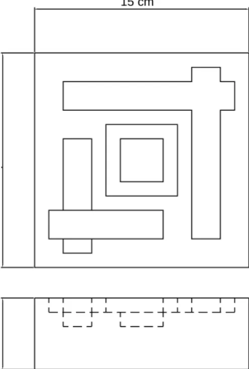
seen inFig. 15has five autonomous features; two pockets and three holes. The second component seen inFig. 16has six pockets that interact with each other two by two.
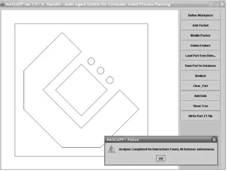
4.1. Test component 1 results
Test component was defined in MASCAPP using the provided feature definition tools. It was then analysed by the multi-agent system.Fig. 17illustrates the analysis results of the agent system.Fig. 18shows an excerpt of the generated ISO14649 file highlighting the autonomous feature defi-nitions.Fig. 19illustrates the part as simulated within the
Siemens ShopMill CNC controller software andFig. 20the actual machined part.
4.2. Test component 2 results
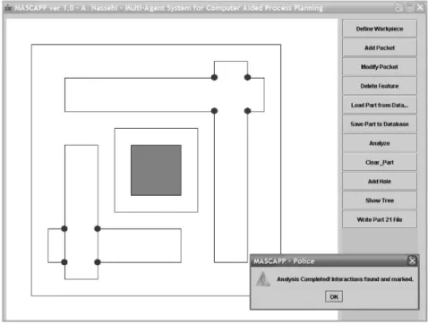
The second test component has interacting features. Four of the six pockets are overlapping and the last two form an enclosing interaction. These interactions are identified and marked by the agents inFig. 21. The STEP-NC file is then generated by MASCAPP. An excerpt of this file high-lighting the compound features can be seen inFig. 22. The
file is then imported into Siemens SHOPMILLe. The
Fig. 17. Test component 1—agent analysis results.
DATA; #1=PROJECT('SAMPLE PROJECT',#2,(#3),$,$,$); #2=WORKPLAN('MAIN WORKPLAN',(#6,#7,#8,#9,#10,#11,#12,#13,#14,#15),$,$,$); #3=WORKPIECE('SIMPLE WORKPIECE',#4,0.010,$,$,#52,()); #4=MATERIAL('ST-50','STEEL',(#5)); #5=PROPERTY_PARAMETER('E=200000N/M2');
#6=MACHINING_WORKINGSTEP('WS ROUGH POCKET 1',#53,#16,#21,$); #7=MACHINING_WORKINGSTEP('WS FINISH POCKET 1',#53,#16,#22,$); #8=MACHINING_WORKINGSTEP('WS ROUGH POCKET 2',#53,#17,#23,$); #9=MACHINING_WORKINGSTEP('WS FINISH POCKET 2',#53,#17,#24,$); #10=MACHINING_WORKINGSTEP('WS DRILL HOLE 1',#53,#18,#25,$); #11=MACHINING_WORKINGSTEP('WS REAM HOLE 1',#53,#18,#26,$); #12=MACHINING_WORKINGSTEP('WS DRILL HOLE 2',#53,#19,#27,$); #13=MACHINING_WORKINGSTEP('WS REAM HOLE 2',#53,#19,#28,$); #14=MACHINING_WORKINGSTEP('WS DRILL HOLE 3',#53,#20,#29,$); #15=MACHINING_WORKINGSTEP('WS REAM HOLE 3',#53,#20,#30,$);
#16=CLOSED_POCKET('POCKET 1',#3,(#21,#22),#60,#54,(),$,#36,$,$,#37); #17=CLOSED_POCKET('POCKET 2',#3,(#23,#24),#62,#55,(),$,#36,$,$,#38); #18=ROUND_HOLE('HOLE 1',#3,(#25,#26),#64,#56,#31,$,#35);
#19=ROUND_HOLE('HOLE 2',#3,(#27,#28),#66,#57,#32,$,#35); #20=ROUND_HOLE('HOLE 3',#3,(#29,#30),#68,#58,#33,$,#35);
simulation by SHOPMILLecan be seen inFig. 23.Fig. 24 shows the machined part.
5. Discussion 5.1. STEP-NC
STEP-NC is a very comprehensive data model. The authors are of the opinion that it is sometimes too complex without any good reasons. For example there are different EXPRESS entities for rectangular pockets and general closed pockets. While this would potentially make STEP-NC code more human readable, it is very hard to justify over-complexity for human readability as this is not one of the intended goals of STEP-NC. By replacing specific data entities with more general ones, coding becomes much easier and more vendors might become interested in adapting their manufacturing software to work with STEP-NC.
5.2. Feature representation
Features are easy to define in prismatic parts and other two and a half dimension manufacturing situations. In more complex configurations it might not be as easy to define a set of possible features. Further research is required for development of a well defined set of machining features for complex machining setups.
5.3. Information storage
While object oriented database systems are more than capable of handling the information storage needs of the
process planning system, the authors appreciate the fact that the usefulness of XML files might make these files the appropriate choice for storing the process data in a process planning system. Further research in this field may prove that the overhead in both space and computer power needed for using XML files is less than that of an object oriented database system.
5.4. Agent application
The intelligent agents defined in MASCAPP handled the job effectively. The authors however believe that agents show a lot of potential for being used in other parts of a Fig. 19. Test component 1—SHOPMILLesimulation.
STEP-NC compliant manufacturing system and their use should not be limited to solving feature interaction problems. Automatic cutting tool and CNC machine selection systems, adaptive interoperable manufacturing systems and integrated global e-manufacturing systems can all be potential candidates for the application of multi-agent systems due to their distributed knowledge and information.
6. Conclusions
† Intelligent agents and distributed artificial intelligence show a lot of potential in development of process planning systems. The fact that process planning for a complex part can be broken down into smaller planning problems, makes these problems manageable by a number of intelligent entities working in tandem. Fig. 21. Test component 2—agent analysis results.
DATA; #1=PROJECT('SAMPLE PROJECT',#2,(#3),$,$,$); #2=WORKPLAN('MAIN WORKPLAN',(#6,#7,#14,#15,#8,#9,#10,#11,#12,#13,#16,#17),$,$,$); #3=WORKPIECE('SIMPLE WORKPIECE',#4,0.010,$,$,#59,()); #4=MATERIAL('ST-50','STEEL',(#5)); #5=PROPERTY_PARAMETER('E=200000N/M2');
#6=MACHINING_WORKINGSTEP('WS ROUGH POCKET 1 COMPOUND',#60,#18,#27,$); #7=MACHINING_WORKINGSTEP('WS FINISH POCKET 1 COMPOUND',#60,#18,#28,$); #8=MACHINING_WORKINGSTEP('WS ROUGH POCKET 2 COMPOUND',#60,#20,#29,$); #9=MACHINING_WORKINGSTEP('WS FINISH POCKET 2 COMPOUND',#60,#20,#30,$); #10=MACHINING_WORKINGSTEP('WS ROUGH POCKET 3 COMPOUND',#60,#20,#31,$); #11=MACHINING_WORKINGSTEP('WS FINISH POCKET 3 COMPOUND',#60,#20,#32,$); #12=MACHINING_WORKINGSTEP('WS ROUGH POCKET 4 COMPOUND',#60,#23,#33,$); #13=MACHINING_WORKINGSTEP('WS FINISH POCKET 4 COMPOUND',#60,#23,#34,$); #14=MACHINING_WORKINGSTEP('WS ROUGH POCKET 5 COMPOUND',#60,#18,#35,$); #15=MACHINING_WORKINGSTEP('WS FINISH POCKET 5 COMPOUND',#60,#18,#36,$); #16=MACHINING_WORKINGSTEP('WS ROUGH POCKET 6 COMPOUND',#60,#23,#37,$); #17=MACHINING_WORKINGSTEP('WS FINISH POCKET 6 COMPOUND',#60,#23,#38,$); #18=COMPOUND_FEATURE('COMPOUND FEATURE 1',#3,(#27,#28,#35,#36),#68,(#19,#25)); #19=CLOSED_POCKET('POCKET 1',#3,(#27,#28),#68,#61,(),$,#41,$,$,#42); #20=COMPOUND_FEATURE('COMPOUND FEATURE 2',#3,(#29,#30,#31,#32),#70,(#21,#22)); #21=CLOSED_POCKET('POCKET 2',#3,(#29,#30),#70,#62,(),$,#41,$,$,#43); #22=CLOSED_POCKET('POCKET 3',#3,(#31,#32),#72,#63,(),$,#41,$,$,#44); #23=COMPOUND_FEATURE('COMPOUND FEATURE 3',#3,(#33,#34,#37,#38),#74,(#24,#26)); #24=CLOSED_POCKET('POCKET 4',#3,(#33,#34),#74,#64,(),$,#41,$,$,#45); #25=CLOSED_POCKET('POCKET 5',#3,(#35,#36),#76,#65,(),$,#41,$,$,#46); #26=CLOSED_POCKET('POCKET 6',#3,(#37,#38),#78,#66,(),$,#41,$,$,#47);
† Intelligent agents can be kept together with the product data after process planning. They can negotiate machining strategies with other intelligent agents responsible for CNC machines or even human users. At a later stage they can be used to control inspection of the part.
† The data model for an automated process planning
system plays a crucial role in success or failure of the software. The ability to store complex geometries and multi-level class hierarchies is essential for development of a robust, rapid and easy to use software system.
† STEP-NC environment with its clear entity definitions and expandable architecture provides a vast potential field for agents. As full product information is
maintained in the STEP-NC architecture, it can serve as an excellent knowledge base for artificial intelligence systems.
Acknowledgements
The authors would like to acknowledge the support of SIEMENS A.G. and in particular the technical assistance of Mr S. Clarke and Mr P. Muller of SIEMENS A.G. in providing access to the STEP-NC translator and the SHOPMILL software. In addition the support of Loughbor-ough University in the form of the studentship for Mr Nassehi is appreciated.
References
[1] ISO 6983-1, International Organization for Standardization-ISO 6983/1-Numerical control of machines-program format and definition of address words—Part 1: Data format for positioning, line and contouring control systems, 1982. First edition, 15/09/1982. [2] M. Hardwick, Digital manufacturing using STEP-NC, AUTOTECH
2001 Conference and Exhibition, AIAG, August 28–30, 2001, Detroit’s Cobo Centre, USA.
[3] ISO 14649-1:2002, Industrial automation systems and integration— physical device control-data model for computerized numerical controllers—Part 1: Overview and Fundamental Principles. Draft International Standard ISO TC184/SC4, 2002.
[4] S.T. Newman, Integrated CAD/CAPP/CAM/CNC manufacture for the 21st century (keynote paper and opening plenary), Proceedings of Fig. 23. Test component 2—SHOPMILLesimulation.
the 14th International Conference on Flexible Automation and Intelligent Manufacturing (FAIM2004), Toronto, Canada July (2004) 1–8.
[5] M.N. Huhns (Ed.), Distributed Artificial Intelligence, Morgan Kaufmann, USA, 1987.
[6] B. Moulin, B. Chaib-draa, An overview of distributed artificial intelligence, in: G. O’Hare, N. Jennings (Eds.), Foundations of Distributed Artificial Intelligence, Wiley, Australia, 1996 (Chapter 1).
[7] M. Woolridge, An Introduction to MultiAgent Systems, Wiley, Chichester, England, 2002.
[8] R.D. Allen, J.A. Harding, S.T. Newman, The application of STEP-NC using agent-based process planning, International Journal of Production Research 42 (24) (2004).
[9] ISO 10303-21, Industrial automation systems and integration. Product Data Representation and Exchange. Implementation Methods. Clear Text Encoding of the Exchange Structure ISO TC184/SC4, 1994. [10] X.W. Xu, Striving for a total integration of CAD, CAPP, CAM
and CNC, Robotics and Integrated Manufacturing 20 (2) (2004) 79–165.
[11] ISO 14649-10: 2002 Industrial Automation Systems and Integration-Physical Device Control-Data model for computerized numerical controllers-Part 10: General process data. Draft International Standard ISO TC184/SC4, 2002.
[12] J.P. Bigus, J. Bigus, Constructing Intelligent Agents with Java, Wiley, New York, 1998.
[13] S.J. Russell, P. Norvig, Artificial Intelligence: A Modern Approach, Prentice–Hall, Englewood Cliffs, NJ, 1995.
[14] S. Franklin, A. Graesser, Is it an agent, or just a program?: a taxonomy for autonomous agents, Proceedings of the Third International Workshop on Agent Theories, Architecture and Languages, Springer, Berlin, 1996.
[15] H.S. Nwana, Software agents: an overview, Knowledge Engineering Review 11 (3) (1996) 205–244.
[16] W. Shen, D.H. Norrie, Agent-based systems for intelligent manu-facturing: a state-of-the-art survey, Knowledge and Information Systems 1 (2) (1999) 129–156.
[17] M.S. Fox, Barbuceanu, R. Teigen, Agent-oriented supply-chain management, The International Journal of Flexible Manufacturing Systems 12 (2000) 165–188.
[18] M. Zweben, M.S. Fox, Intelligent Scheduling, Morgan Kaufman, San Francisco, CA, 1994.
[19] H. Hayashi, The IMS International Collaborative Program, in: Proceedings of 24th ISIR, Japan Industrial Robot Association, 1993. [20] E.H. Van Leeuwen, D.H. Norrie, Intelligent manufacturing: holons
and holarchies, Manufacturing Engineer 76 (2) (1997) 86–88. [21] C.C. Hayes, MAPP: an agent organisation for process planning,
Second International Conference on Autonomous Agents Workshop on Agent-Based Manufacturing, 1998.
[22] S. Kornienko, O. Kornienko, P. Levi, Flexible manufacturing process planning based on the multi-agent technology, in: Proceedings of the 21st International Conference AIA’03, Innsbruck, Austria, 2003 pp. 156–161.
[23] S. Kornienko, O. Kornienko, P. Levi, Multi-agent repairer of damaged process plans in manufacturing environment, in: Proceedings of Eighth International Conference on Intelligent Autonomous Systems, Amsterdam, March 2004.
[24] J.K. Tauber, Teach Yourself XML in 21 Days, SAMS, Indiana Polis, Indiana, 1998.
[25] E.T. Ray, Learning XML, O’Reilly, UK, 2001.
[26] M.J. Hernandez, Database Design for Mere Mortals: A Hands-on Guide to Relational Database Design, second ed., Addison–Wesley, Boston, 2003.
[27] T.J. Waltz, D. Yen, S. Lee, Object-oriented database systems: an implementation plan, Industrial Management and Data Systems 95 (6) (1995) 8–17.
[28] A. Evans, R. France, K. Lano, B. Rumpe, Developing the UML as a formal modeling notation, in: P.A. Miller, J. Bezivin (Ed.), Proceedings of UML’98 International Workshop, Mulhouse, France, June 3–4, 1998, 1998.
[29] J. Rumbaugh, OMT: The object model, Journal of Object-Oriented Programming 7 8 (1995) 21–27.
[30] http://www.objectstore.com/docs/datasheets/products/objectstore_da-tasheet.pdfInternet website as accessed on 21.01.2005.