Juniper Networks Security Appliances
Security Target
Version 2.0
March 5, 2010
Prepared for:Juniper Networks
1194 North Mathilda Ave Sunnyvale, CA 94089-1206Prepared By:
Science Applications International Corporation
Common Criteria Testing Laboratory
6841 Benjamin Franklin Drive Columbia, MD 21046
1. SECURITY TARGET INTRODUCTION ...5
1.1 SECURITY TARGET,TOE AND CCIDENTIFICATION...5
1.2 CONFORMANCE CLAIMS...6 1.3 CONVENTIONS...6 1.4 TERMINOLOGY...7 2. TOE DESCRIPTION ...12 2.1 TOEOVERVIEW...12 2.2 PRODUCT DESCRIPTION...12 2.2.1 Hardware...13 2.2.2 ScreenOS ...13 2.2.3 Policies ...13 2.2.4 Services ...14 2.3 TOECONFIGURATIONS...14 2.3.1 Interface Modes ...14 2.3.2 VPN...17 2.4 TOEARCHITECTURE...18 2.4.1 Physical Boundaries ...18 2.4.2 Logical Boundaries...18 2.5 TOEDOCUMENTATION...22 3. SECURITY ENVIRONMENT...23 3.1 ORGANIZATIONAL POLICIES...23 3.2 THREATS...23 3.3 ASSUMPTIONS...24 4. SECURITY OBJECTIVES ...25
4.1 SECURITY OBJECTIVES FOR THE TOE...25
4.2 SECURITY OBJECTIVES FOR THE ENVIRONMENT...26
5. IT SECURITY REQUIREMENTS...28
5.1 TOESECURITY FUNCTIONAL REQUIREMENTS...28
5.1.1 Security audit (FAU)...31
5.1.2 Cryptographic support (FCS) ...33
5.1.3 User data protection (FDP)...37
5.1.4 Identification and authentication (FIA) ...44
5.1.5 Security management (FMT) ...45
5.1.6 Protection of the TSF (FPT) ...49
5.1.7 Resource utilization (FRU) ...50
5.1.8 TOE access (FTA)...50
5.1.9 Trusted path/channels (FTP) ...51
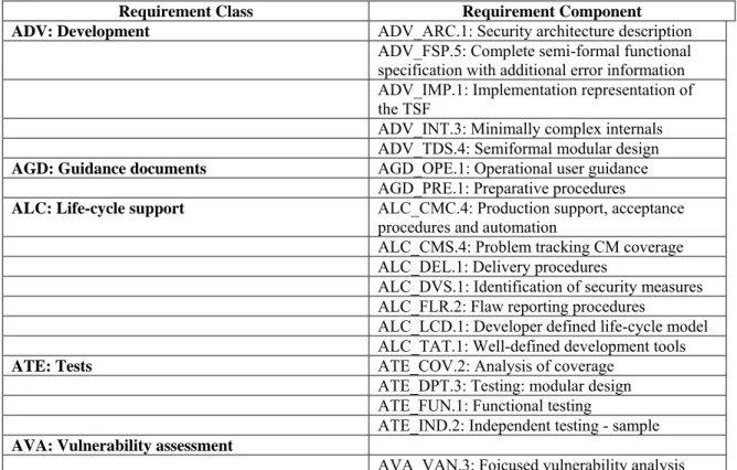
5.2 TOESECURITY ASSURANCE REQUIREMENTS...52
5.2.1 Development (ADV)...52
5.2.2 Guidance documents (AGD) ...54
5.2.3 Life-cycle Support (ALC) ...55
5.2.4 Tests (ATE) ...57
5.2.5 Vulnerability assessment (AVA)...57
6. TOE SUMMARY SPECIFICATION ...59
6.1 TOESECURITY FUNCTIONS...59
6.1.1 Security audit ...59
6.1.2 Cryptographic support...63
6.1.3 User data protection ...66
6.1.5 Security management...73
6.1.6 Protection of the TSF...75
6.1.7 Resource utilization ...76
6.1.8 TOE access ...77
6.1.9 Trusted path/channels...77
7. PROTECTION PROFILE CLAIMS...79
7.1 SECURITY ENVIRONMENT...79
7.2 SECURITY FUNCTIONAL REQUIREMENTS...81
7.3 ASSURANCE REQUIREMENTS...85
8. RATIONALE ...86
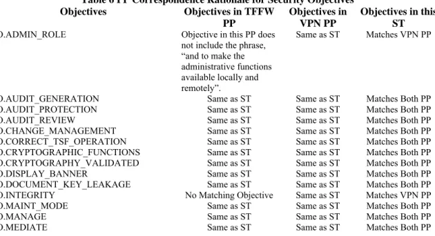
8.1 SECURITY OBJECTIVES RATIONALE...86
8.2 SECURITY REQUIREMENTS RATIONALE...86
8.3 REQUIREMENT DEPENDENCY RATIONALE...86
8.4 EXTENDED REQUIREMENTS RATIONALE...86
8.5 TOESUMMARY SPECIFICATION RATIONALE...86
8.6 PPCLAIMS RATIONALE...88
9. AUDIT EVENTS ...89
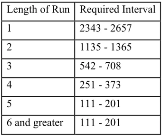
10. STATISTICAL RANDOM NUMBER GENERATOR TESTS...96
LIST OF TABLES Table 1 TOE Security Functional Requirements...31
Table 2 Medium Robustness Assurance Requirements...52
Table 3 PP Correspondence Rationale for Threats...79
Table 4 PP Correspondence Rationale for Security Policies...80
Table 5 PP Correspondence Rationale for Assumptions...80
Table 6 PP Correspondence Rationale for Security Objectives...80
Table 7 PP Correspondence Rationale for Objectives for the Environment...81
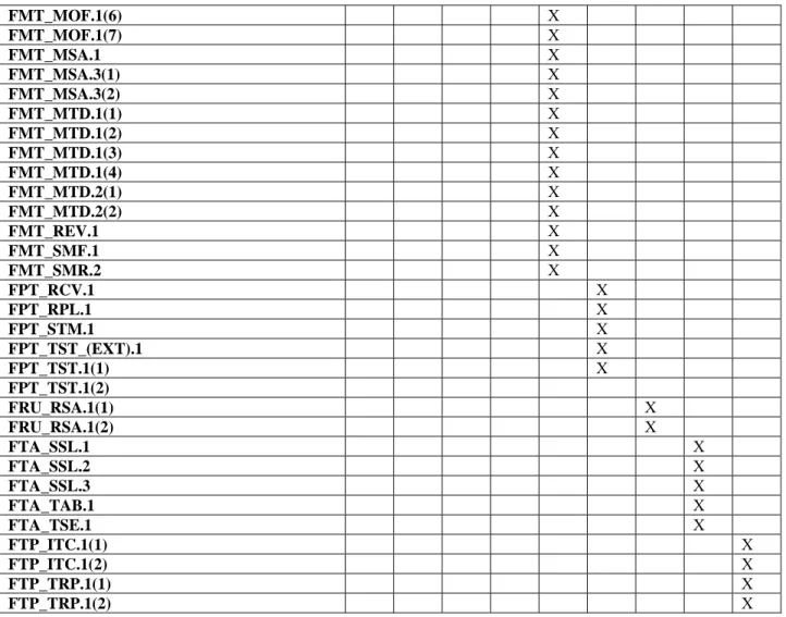
Table 8 PP Correspondence Rationale for SFRs...81
1. Security Target Introduction
This section identifies the Security Target (ST) and Target of Evaluation (TOE) identification, ST conventions, ST conformance claims, and the ST organization. The TOE is Security Appliances provided by Juniper Networks. The security appliances Target of Evaluation (TOE) primarily supports the definition of and enforces information flow policies among network nodes. The security appliance provides for stateful inspection of every packet that traverses the network via the TOE. All information flow from one network node to another passes through a security appliance, if the network and appliances are properly connected and configured. Information flow is controlled on the basis of network node addresses, protocol, and services requested. In support of the information flow security functions, a security appliance ensures that security relevant activity is audited, that its own functions are protected from potential attacks, and provides the security tools to manage all of it’s security functions.
The Security Target contains the following additional sections: TOE Description (Section 2)
Security Environment (Section 3) Security Objectives (Section 4) IT Security Requirements (Section 5) TOE Summary Specification (Section 6) Protection Profile Claims (Section 7) Rationale (Section 8)
Audit Events (Section 9)
Statistical Random Number Generator Tests (Section 10)
1.1
Security Target, TOE and CC Identification
ST Title – Juniper Networks Security Appliances Security Target ST Version – Version 2.0
ST Date – March 5, 2010
TOE Identification – The TOE consists of one or more of the following security appliances running the specified
ScreenOS firmware version:
Product Part Numbers Firmware Version
Juniper Networks NetScreen ISG 1000
NS-ISG-1000, NS-ISG-1000-DC, NS-ISG-1000B, NS-ISG-1000B-DC
6.2.0r3a
Juniper Networks NetScreen ISG 2000
NS-ISG-2000, NS-ISG-2000-DC, NS-ISG-2000B, NS-ISG-2000B-DC
6.2.0r3a Juniper Networks NetScreen 5200 NS-5200, NS-5200-DC 6.2.0r3a Juniper Networks NetScreen 5400 NS-5400, NS-5400-DC 6.2.0r3a Juniper Networks SSG5 Secure Services Gateway SSG-5-SB, SSG-5-SH 6.2.0r3
Juniper Networks SSG20 Secure Services Gateway SSG-20-SB, SSG-20-SH 6.2.0r3 Juniper Networks SSG140 Secure Services Gateway SSG-140-SB, SSG-140-SH 6.2.0r3 Juniper Networks SSG320M Secure Services Gateway SSG-320M-SH, SSG-320M-SH-N-TAA,
SSG-320M-SH-DC-N-TAA
6.2.0r3 Juniper Networks SSG350M Secure Services Gateway SSG-350M-SH, SSG-350M-SH-N-TAA,
SSG-350M-SH-DC-N-TAA 6.2.0r3 Juniper Networks SSG520M Secure Services Gateway SSG-520M-SH, SSG-520M-SH-N-TAA,
SSG-520M-SH-DC-N-TAA 6.2.0r3 Juniper Networks SSG550M Secure Services Gateway
SSG-550M-SH,
SSG-550M-SH-N-TAA,
SSG-550M-SH-DC-N-TAA 6.2.0r3
TOE Developer – Juniper Networks Evaluation Sponsor – Juniper Networks
CC Identification – Common Criteria for Information Technology Security Evaluation, Version 3.1, September,
2007
1.2
Conformance Claims
This ST and the TOE it describes are conformant to the following CC specifications:
Common Criteria for Information Technology Security Evaluation Part 2: Security Functional Requirements, Version 3.1, September, 2007.
Part 2 Extended
Common Criteria for Information Technology Security Evaluation Part 3: Security Assurance Requirements, Version 3.1, September, 2007.
Part 3 Conformant - EAL 4
Assurance Level: EAL4 augmented with ADV_FSP.5, ADV_INT.3, ADV_TDS.4, ALC_FLR.2, ATE_DPT.3, and AVA_VAN.3
The TOE meets all of the security requirements of the following Protection Profiles, except for AVA_CCA_(EXT).1 and AVA_VAN.4:
U.S. Government Virtual Private Network (VPN) Boundary Gateway Protection Profile For Medium Robustness Environments, Version 1.2, 30 January 2009 (VPN PP). 1
U.S. Government Traffic-Filter Firewall Protection Profile For Medium Robustness Environments, Version 1.1, July 25, 2007 (TFFW PP).
1.3
Conventions
Since this security target is claiming compliance with two PPs, the conventions used inthis security target are intended to highlight the completion of operations made within this security target. While this security target will include the operations made by the PPs upon the CC requirements it is not the author’s intent to highlight those operations (i.e., use bold, italics or special fonts). Therefore, keywords (e.g., selection, assignment and refinement)
1 The testing associated with AVA_CCA_(EXT).1 and AVA_VAN.4 as required by these Protection Profiles is pending completion by NSA.
and formatting (e.g., special fonts) used within the PPs to designate operations are being removed by this ST. The brackets used by the PPs to designate operations completed by the PP are left in the requirements.
The following conventions have been applied to indicate operations that this ST is making to the requirements in the Medium Robustness VPN Protection Profile:
Security Functional Requirements – Part 2 of the CC defines the approved set of operations that may be applied to functional requirements: iteration, assignment, selection, and refinement.
o Iteration: allows a component to be used more than once with varying operations. In the ST, iteration is indicated by a number in parentheses placed at the end of the component. For example FDP_ACC.1(1) and FDP_ACC.1(2) indicate that the ST includes two iterations of the FDP_ACC.1 requirement, (1) and (2).
o Assignment: allows the specification of an identified parameter. Assignments are indicated using bold and are surrounded by brackets (e.g., [assignment]). Note that an assignment within a
selection would be identified in italics and with embedded bold brackets (e.g., [[selected-assignment]]).
o Selection: allows the specification of one or more elements from a list. Selections are indicated using bold italics and are surrounded by brackets (e.g., [selection]).
o Refinement: allows the addition of details. Refinements are indicated using bold, for additions, and strike-through, for deletions (e.g., “… all objects …” or “… some big things …”).
Other sections of the ST – Other sections of the ST use bolding to highlight text of special interest, such as captions.
In many cases, a requirement in the TFFW PP is identical to a requirement in the VPN PP. When these two PPs change a requirement in a significantly different manner, this security target will restate the requirement such that all aspects of both versions of the requirement are specified, thus making the version of the requirement in this ST a superset of the required functionality from these two PPs. For requirements that are in the TFFW PP and not in the VPN PP this security target will append “_(FW)” to the requirement name. The exception to this is the FDP_IFC and FDP_IFF.1 requirements. Simple iterations have been performed upon these requirements because the SFP defined within these requirements makes it clear which iteration is from the VPN PP and which is from the TFFW PP. For all of the TFFW specific requirements (i.e., those denoted with “_(FW)”), the assignment, selection and refinement conventions mentioned above will be used to denote operations performed by this ST with respect to the requirement as found in the TFFW PP.
The CC paradigm also allows protection profile and security target authors to create their own requirements. Such requirements are termed ‘extended requirements’ and are permitted if the CC does not offer suitable requirements to meet the authors’ needs. Extended requirements must be identified and are required to use the CC class/family/component model in articulating the requirements. In these PPs, extended requirements are indicated with the “(EXT)” following the component name. This security target reproduces that convention.
1.4
Terminology
Address The network portion of an IP address. Most IP addresses have a network portion and a node portion. Address Shifting
A mechanism for creating a one-to-one mapping between any original address in one range of addresses and a specific translated address in a different range.
Application-Specific
Integrated Circuit (ASIC) A customized microchip, which is designed for a specific application. Authorized
Administrator
A role which human users may be associated with to administer the security parameters of the TOE. Such users are not subject to any access control requirements once authenticated to the TOE and are therefore trusted to not compromise the security policy enforced by the TOE.
Authorized external server
Any IT product or system, outside the scope of the TOE that may administer the security parameters of the TOE. Such servers are not subject to any access control requirements once authenticated to the TOE and are therefore trusted to not compromise the security policy enforced by the TOE.
Central Processing Unit
(CPU) The CPU controls the operation of a computer.
Destination Network Address Translation (NAT-dst)
The translation of the original destination IP address in a packet header to a different destination address. ScreenOS supports the translation of one or several original destination IP addresses to a single IP address (“one-to-one” or “many-to-one” relationships). The TOE also supports the translation of one range of IP addresses to another range (a “many-to-many” relationship) using address shifting.
When the TOE performs NAT-dst without address shifting it can also map the destination port number to a different predetermined port number. When the TOE performs NAT-dst with address shifting, it cannot also perform port mapping.
Dynamic IP (DIP) Pool
A dynamic IP (DIP) pool is a range of IPv4 addresses from which the security appliance can dynamically or deterministically take addresses to use when performing network address translation on the source IPv4 address (NAT-src) in IP packet headers.
Dynamic Random Access Memory (DRAM)
A type of computer memory that is stored in capacitors on a chip. Most computers have DRAM chips, because they provide a lot of memory at a low cost.
External server Any IT product or system, untrusted or trusted, outside of the TOE that interacts with the TOE. Federal Information
Processing Standards (FIPS)
The Federal Information Processing Standards Publication (FIPS PUB) series issued by the U.S. National Institute of Standards and Technology as technical guidelines for U.S. Government procurements of information processing system equipment and services.
FIPS 140-2
The U.S. Government standard for security requirements to be met by a cryptographic module used to protect unclassified information in computer and communication systems. The standard specifies four increasing levels (from 'Level 1' to 'Level 4') of requirements to cover a wide range of potential applications and environments. The requirements address basic design and documentation, cryptographic module ports and interfaces, authorized roles and services, physical security, operational environment, cryptographic key management, electromagnetic interference and electromagnetic compatibility (EMI/EMC), and self-testing.
Firmware
Software stored in Read Only Memory (ROM) or Programmable Read-Only Memory(PROM) essential programs that remain even when the system is turned off. Firmware is easier to change than hardware but more permanent than software stored on disk.
Flash Memory
A small printed circuit board that holds large amounts of data in memory. Flash memory is used because it is small and holds its data when the computer is turned off.
Hyper Text Transfer Protocol (HTTP)
The protocol most commonly used in the World-Wide Web to transfer information from Web servers to Web browsers.
Internet Control Message Protocol (ICMP)
An extension to the Internet Protocol (IP), which is used to communicate between a gateway and a source host, to manage errors and generate control messages.
IP Security (IPSEC)
An IP security protocol that provides for encapsulation of standard IP packets into Type 51 IP, allowing firewalls to recognize and admit encapsulated, encrypted data.
Mapped IP Address (MIP)
A MIP is a direct one-to-one mapping of traffic destined from one IP address to another IP address. The TOE forwards incoming traffic destined for a MIP to the host with the address to which the MIP points. Essentially, a MIP is static destination address translation, mapping the destination IP address in an IP packet header to another static IP address. When a MIP host initiates outbound traffic, the TOE translates the source IP address of the host to that of the MIP address. This bidirectional translation symmetry differs from the behavior of source and destination address translation. MIPs allow inbound traffic to reach private addresses in a zone whose interface is in NAT mode. MIPs also provide part of the solution to the problem of overlapping address spaces at two sites connected by a VPN tunnel.
Network Address Translation (NAT)
NAT involves translating the source IP address in a packet header to a different IP address. In the case of a traditional NAT, the translated source IP address comes from the IP address of the egress interface. When the security appliance uses the IP address of the egress interface, it translates all original source IP addresses to the address of the egress interface.
NAT Source (NAT-src)
NAT-src involves translating the source IP address in a packet header to a different IPv4 address from a dynamic IPv4 (DIP) address pool. When the security appliance draws addresses from a DIP pool, it can do so
dynamically or deterministically. When doing the former, it randomly draws an address from the DIP pool and translates the original source IPv4 address to the randomly selected address. When doing the latter, it uses address shifting to translate the source IPv4 address to a predetermined IPv4 address in the range of addresses that constitute the pool.
Network Basic Input/Output System (NetBIOS)
An application programming interface used in conjunction with other programs to transmit messages between applications running on PCs hooked to a local area network.
Network
A composition of a communications medium and components attached to that medium whose responsibility is the transfer of information. Such components may include automated information systems, packet switches, telecommunications controllers, distribution centers, technical management, and control devices. It is a set of devices such as computers, terminals, and printers that are physically connected by a transmission medium so that they can communicate with each other.
Node A concentration point in a network where numerous trunks come together at the same switch. Packet A block of data sent over the network transmitting the identities of the sending and receiving stations, error-control information, and message. Port Address Translation
(PAT)
The translation of the original source port number in a packet to a different, randomly designated port number.
Public-Key
Infrastructure (PKI)
A system of Certificate Authorities (CAs) (and, optionally, Registration Authorities (RAs) and other supporting servers and agents) that perform some set of certificate management, archive management, key management, and token management functions for a community of users in an application of asymmetric cryptography.
Session
A series of interactions between two communication end points that occur during the span of a single connection. Typically, one end point requests a connection with another specified end point and if that end point replies agreeing to the connection, the end points take turns exchanging commands and data ("talking to each other"). The session begins when the connection is established at both ends and terminates when the connection is ended.
Session Table
A resource within the security appliance that maintains a list of active sessions. The session table is utilized to verify if any requesting information flows may already have an established session.
Stateful inspection
Also referred to as dynamic packet filtering. Stateful inspection is a firewall mechanism that works at the network layer. Unlike static packet filtering, which examines a packet based on the information in its header, stateful inspection tracks each connection traversing all interfaces of the firewall and makes sure they are valid. An example of a stateful firewall may examine not just the header information but also the contents of the packet up through the application layer in order to determine more about the packet than just information about its source and destination. A stateful inspection firewall also monitors the state of the connection and compiles the information in a state table. Because of this, filtering decisions are based not only on administrator-defined rules (as in static packet filtering) but also on context that has been established by prior packets that have passed through the firewall. As an added security measure against port scanning, stateful inspection firewalls close off ports until connection to the specific port is requested.
Synchronous Dynamic Random Access Memory (SDRAM)
High-speed DRAM that adds a separate clock signal to the control signals. SDRAM can transfer bursts of non-contiguous data at 100 MBytes/sec, and has an access time of 8-12 nanoseconds. It comes in 64-bit modules: long 168-pin Dual In-line Memory Modules (DIMMs).
Tampering
An unauthorized modification that alters the proper functioning of
equipment or a system in a manner that degrades the security or functionality it provides.
Transmission Control Protocol/Internetwork Protocol (TCP/IP)
A communications protocol developed under contract from the U.S. Department of Defense to internetwork dissimilar systems. Transport Control Protocol/Internet Protocol. Refers to the Internet Protocol Suite, which includes TCP and IP, as well as several other protocols, used by computers to communicate with each other. TCP/IP is the standard protocol used on the Internet. It can also be used as a communications protocol in the private networks called intranets and in extranets. TCP/IP is a two-layered protocol The higher layer, Transmission Control Protocol, manages the marshalling of a message or file into smaller packets that are transmitted over the Internet and received by a TCP layer that reassembles the packets into the original message. The lower layer, Internet Protocol, handles the address part of each packet so that it gets to the right destination.
Tunneling Use of one data transfer method to carry data for another method.
User Datagram Protocol (UDP)
A communications protocol for the Internet network layer, transport layer, and session layer, which makes it possible to send a datagram message from one computer to an application running in another computer. Like TCP (Transmission Control Protocol), UDP is used with IP (the Internet Protocol). Unlike TCP, UDP is connectionless and does not guarantee reliable communication; the application itself must process any errors and check for reliable delivery.
Virtual IP Address (VIP)
A Virtual IP address (VIP) maps traffic received at one IP address to another address based on the destination port number in the packet header. In other words, the actual destination IP addresses for two VIPs can be the same, yet the TOE uses destination port number to determine where to forward traffic.
Virtual Private Network (VPN)
An Internet-based system for information communication and enterprise interaction. A VPN uses the Internet for network connections between people and information sites. It includes stringent security mechanisms so that sending private and confidential information is as secure as in a traditional closed system.
Virtual Router (VR)
A virtual router (VR) is the component of ScreenOS that performs routing functions. A virtual router functions as a router. It has its own interfaces and its own routing table. By default, a security appliance supports two virtual routers: Untrust-VR and Trust-VR. This allows the security appliance to maintain two separate routing tables and to conceal the routing information in one virtual router from the other. For example, the untrust-vr is typically used for communication with untrusted parties and does not contain any routing information for the protected zones. Routing information for the protected zones is maintained by the trust-vr. Thus, no internal network information can be gleaned by the surreptitious extraction of routes from the untrust-vr.
Virtual System
A virtual system (vsys) is a subdivision of the main system that appears to the user to be a stand-alone entity. Virtual systems reside separately from each other in the same security appliance. Each one can be managed by its own virtual system administrator.
Virtual systems are outside the scope of the evaluated configuration of the TOE.
Zone(s)
A zone can be a segment of network space to which security measures are applied (a security zone), a logical segment to which a VPN tunnel interface is bound (a tunnel zone), or either a physical or logical entity that performs a specific function (a function zone).
2.
TOE Description
The Target of Evaluation (TOE) is Security Appliances.
Juniper Networks Security Appliances, hereafter referred to as security appliances, are integrated security network devices designed and manufactured by Juniper Networks, 1194 North Mathilda Avenue, Sunnyvale, California 94089-1206 U.S.A, herein called simply Juniper. The security appliances consist of integrated security network appliances that operate as a central security hub in a networked configuration. The security appliances control traffic flow through the network. The security appliances integrate stateful packet inspection firewall and traffic management features.
2.1
TOE Overview
Juniper's line of security appliances combines firewall, virtual private networking (VPN), and traffic management functions. All security appliances have hardware accelerated IPSec encryption and very low latency, allowing them to fit into any network. Installing and managing appliances is accomplished using a command line interface (CLI). The TOE includes the security appliances that run ScreenOS, a custom operating system. The security appliances that meet the definition of TOE include several models. Each identified model consists of hardware and ScreenOS that runs in firmware. The set of models included are identified in Section 1.1 of this document.
The security appliances use a technique known as 'stateful inspection' rather than an 'application proxy,' as stateful inspection offers the combination of security and performance. Stateful inspection firewalls examine each packet, and track application-layer information for each connection, by setting up a state table that spans multiple packets. This is used to determine whether incoming packets are legitimate. It eliminates the requirement to establish a TCP session with the firewall itself to access a service on the other side of the firewall (i.e. proxy the service).
To perform routing functions ScreenOS relies on a virtual router (VR) component, which functions as a router and has its own interfaces and its own routing table. In ScreenOS, a security appliance supports two predefined virtual routers, trust-vr and untrust-vr. This allows the security appliance to maintain two separate routing tables and to conceal the routing information in one virtual router from the other. For example, the untrust-vr is typically used for communication with untrusted parties and does not contain any routing information for the protected zones. Routing information for the protected zones is maintained by the trust-vr. Thus, no internal network information can be gleaned by the surreptitious extraction of routes from the untrust-vr. There are no limitations on the number of virtual routers to be used in the evaluated configuration.
2.2
Product Description
Juniper Networks Security Appliances all share a very similar hardware architecture and packet flow. All run ScreenOS with common core features across all products. All security appliances perform the same security functions and export the same types of interfaces. A sample of the differences between these products is listed below.
· The SSG 5 and SSG 20 use an Intel IXP625 ASIC; the SSG 140 uses the Intel IXP2325. The Intel IXP ASICs provide acceleration of AES, 3DES and SHA-1. The remaining cryptographic and firewall functionality is performed in software. The SSG 140, 320M, 350M, 520M and 550M use the Cavium Nitrox Lite ASIC
· The SSG 140, 320M, 350M, 520M and 550M use the Cavium Nitrox Lite ASIC to accelerate AES, 3DES, SHA-1 and modular exponentiation operations. The remaining cryptographic and firewall functionality is performed in software.
· The Juniper Networks NetScreen-5200, NetScreen-5400, NetScreen-ISG1000 and NetScreen-ISG2000 use one or more custom GigaScreen3 ASICs The GigaScreen3 ASIC is capable of providing most of the firewall and cryptographic functionality, and uses the CPU as a co-processor for handling
management traffic and first packet inspections (policy lookups). The GigaScreen3 ASIC can process an incoming packet, perform a session lookup, NAT, TCP/IP sequence checking, and can then send the
packet back out of the device without the CPU every seeing it. The only time the CPU is used is for first packet inspection, management traffic, and packet fragment reassembly for inspection. These platforms use the Cavium Nitrox Lite ASIC for acceleration of modular exponentiation operations.
2.2.1
Hardware
The hardware is manufactured to Juniper’s specifications by sub-contracted manufacturing facilities. Juniper’s custom OS, ScreenOS, runs in firmware. The security appliances provide no extended permanent storage like disk drives and no abstractions like files. Audit information is stored in memory because of the large storage capabilities. The main components of a security appliance are the processor, ASIC, memory, interfaces, and surrounding chassis and components. The differences between security appliances are the types of processor(s), traffic interfaces, management interfaces, number of power supplies, type of ASIC, and redundancy to ensure high availability.
2.2.2
ScreenOS
ScreenOS firmware powers the entire system. At its core is a custom-designed, real time operating system built from the outset to deliver security and performance. ScreenOS provides an integrated platform for its functions, including:
Stateful inspection firewall Traffic management Site-to-Site VPN
ScreenOS does not support a programming environment.
2.2.3
Policies
Security appliances enforce information flow control decisions by defining policies which permit, deny, reject, nat or tunnel information flows in accordance with the rules defined in each policy. All policies on a security appliance include the following attributes:
Direction – The direction of traffic between two security zones (from a source zone to a destination zone)
Source address – The address from which traffic initiates Destination address – The address to which traffic is sent Service – The type of traffic transmitted
Action – The action that the security appliance performs when it receives traffic meeting the first four criteria: permit, deny (drop silently), reject (drop with ICMP error), nat (perform address translation), or tunnel (permit with encryption or decryption).
Security appliances provide three different types of policies which support the information flow control decisions enforced by the TOE. This includes Interzone Policies, Intrazone Policies, and Global Policies. These policies are invoked when determining the appropriate decision to make on an information flow (Global policy lookup is not supported by the TOE in Authenticated Transparent Mode). The following sections describe differences between each of these three types of policies.
2.2.3.1 Interzone policies
Interzone policies provide traffic control between security zones. You can set interzone policies to permit, deny, or tunnel traffic from one zone to another. Using stateful inspection techniques, the TOE maintains a table of active TCP sessions and active UDP “pseudo” sessions so that it can allow replies to service requests.
2.2.3.2 Intrazone Policies
policies, intrazone policies control traffic flowing unidirectionally. To allow traffic initiated at either end of a data path, you must create two policies—one policy for each direction.
Intrazone policies do not support VPN tunnels or source network address translation (NAT-src) when it is set at the interface level (set interface nat). However, intrazone policies do support policy-based NAT-src and NAT-dst. They also support destination address translation when the policy references a mapped IP (MIP) as the destination address. A mapped IPv4 address is a direct one-to-one mapping of traffic destined for one IPv4 address to another IPv4 address.
2.2.3.3 Global Policies
Unlike interzone and intrazone policies, global policies do not reference specific source and destination zones. Global policies reference user-defined Global zone addresses or the predefined Global zone address “any”. These addresses can span multiple security zones. For example, if you want to provide access to or from multiple zones, you can create a global policy with the Global zone address “any”, which encompasses all addresses in all zones.
2.2.3.3.1 Order of Invocation
When the TOE initiates a policy lookup, it first checks to see if the security zones are the same or different. If the zones are different, the TOE performs a policy lookup in the interzone policy set list. If the zones match, the TOE performs a policy lookup in the intrazone policy set. If a policy is not found within either the interzone or intrazone set lists, the TOE performs a policy lookup in the global policy set list.
2.2.3.3.2 Firewall User Authentication
A firewall policy may require authentication prior to permitting traffic to cross the firewall. The authentication option may be combined with an interzone, intrazone or global policy and requires a username and password to be provided via IKE, XAuth, L2TP, HTTP, FTP or telnet. Successful authentication does not grant administrative access to the TOE.
2.2.4
Services
Security appliances enforce policies based on a service. A service specifies the protocol (TCP or UDP), the port number, the service group, the timeout and the flag associated to a specific service and maps the service to a defined name.
2.3
TOE Configurations
The TOE supports a variety of configurations. The TOE provides three possible ways to configure a network interface. A network interface may be configured to operate in Transparent Mode, NAT Mode, or Route Mode. In addition, the TOE also supports Site-To-Site VPNs using a pre-shared key for authentication. These various configurations are further described below.
2.3.1
Interface Modes
The TOE supports three types of interface modes. These interface modes include a Transparent Mode, NAT Mode, and Route Mode, each of which determines how packets are routed and filtered by the TOE. Each instance of the TOE can include one, a combination of, or all three interface modes. However, each individual network interface may only be configured with one interface mode and may not share a combination of or all three interface modes with one physical network interface. Each interface mode consistently satisfies all of the TOE security functional requirement claims identified in this ST. These three interface modes are further described below.
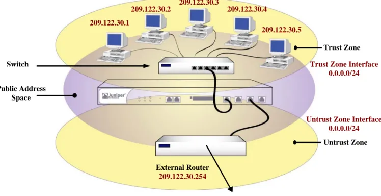
2.3.1.1 Transparent Mode
When a TOE interface is configured in Transparent Mode, the TOE filters packets traversing the firewall without modifying any of the source or destination information in the IP packet header. All interfaces behave as though they are part of the same network, with the TOE acting much like a Layer 2 switch or bridge. In Transparent mode, the IP addresses of interfaces are set at 0.0.0.0, making the presence of the TOE invisible, or “transparent,” to users. The FDP_IFC.1(1), FDP_IFC.1(4), FDP_IFF.1(1), and FDP_IFF.1(4) security functional requirements specify the requirements for protecting information flows on a security appliance when it is configured in transparent mode.
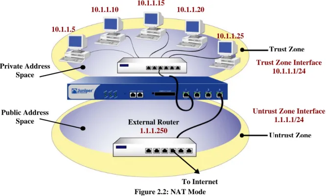
Figure 2.1: Transparent Mode 2.3.1.2 NAT Mode
When an ingress interface is in Network Address Translation (NAT) mode, the security appliance, acting like a Layer 3 switch (or router), translates two components in the header of an outgoing IP packet destined for the Untrust zone: its source IP address and source port number. The security appliance replaces the source IP address of the originating host with the IP address of the Untrust zone interface. Also, it replaces the source port number with another random port number generated by the security appliance.
When the reply packet arrives at the security appliance, the device translates two components in the IP header of the incoming packet: the destination address and port number, which are translated back to the original numbers. The security appliance then forwards the packet to its destination. NAT adds a level of security not provided in Transparent mode: The addresses of hosts sending traffic through an ingress interface in NAT mode (such as a Trust zone interface) are never exposed to hosts in the egress zone (such as the Untrust zone) unless the two zones are in the same virtual routing domain and the security appliance is advertising routes to peers through a dynamic routing protocol (DRP). Even then, the Trust zone addresses are only reachable if you have a policy permitting inbound traffic to them. (If you want to keep the Trust zone addresses hidden while using a DRP, then put the Untrust zone in the untrust-vr and the Trust zone in the trust-vr, and do not export routes for internal addresses in the trust-vr to the untrust-vr.) If the security appliance uses static routing and just one virtual router, the internal addresses remain
Public Address Space Switch Untrust Zone Trust Zone 209.122.30.5 209.122.30.4 209.122.30.3 209.122.30.2 209.122.30.1 To Internet External Router 209.122.30.254
Untrust Zone Interface 0.0.0.0/24 Trust Zone Interface
you use only mapped IP (MIP) and virtual IP (VIP) addresses as the destinations in your inbound policies, the internal addresses still remain hidden.
The FDP_IFC.1(2), FDP_IFC.1(5), FDP_IFF.1(2) and FDP_IFF.1(5) security functional requirements specify the requirements for protecting information flows on a security appliance when it is configured in NAT mode.
Figure 2.2: NAT Mode
2.3.1.3 Route Mode
When an interface is in Route mode, the security appliance routes traffic between different zones without performing source NAT (NAT-src); that is, the source address and port number in the IP packet header remain unchanged as it traverses the security appliance. Unlike NAT-src, you do not need to establish mapped IP (MIP) and virtual IP (VIP) addresses to allow inbound traffic to reach hosts when the destination zone interface is in Route mode. Unlike Transparent mode, the interfaces in each zone are on different subnets.
In NAT Mode, Network Address Translation is applied to all IPv4 traffic arriving at the untrust interface. By default, no address translation is provided in Route mode. However, selective network address translation is possible in Route mode using policy definitions. You can determine which traffic to route and on which traffic to perform NAT-src by creating policies that enable NAT-src for specified source addresses on either incoming or outgoing traffic. For network traffic, NAT can use the IPv4 address or addresses of the destination zone interface from a Dynamic IP (DIP) pool, which is in the same subnet as the destination zone interface. For VPN traffic, NAT can use a tunnel interface IPv4 address or an address from its associated DIP pool.
The FDP_IFC.1(2), FDP_IFC.1(5), FDP_IFF.1(2) and FDP_IFF.1(5) security functional requirements specify the requirements for protecting information flows on a security appliance when it is configured in route mode.
Untrust Zone Trust Zone Public Address Space Private Address Space External Router 1.1.1.250
Untrust Zone Interface 1.1.1.1/24 Trust Zone Interface
10.1.1.1/24 10.1.1.25 10.1.1.20 10.1.1.15 10.1.1.10 10.1.1.5 To Internet
Figure 2.3: Route Mode
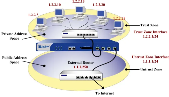
2.3.2
VPN
Site-To-Site VPNs allow an organization to securely connect to a remotely connected network. The TOE supports and defines security claims FDP_IFC.1(1) and FDP_IFF.1(1) for Transparent Mode, and FDP_IFC.1(2) and FDP_IFF.1(2) for Route Mode and NAT Mode, for utilizing Site-To-Site VPN connections using pre-shared key (PSK) and certificate-based authentication. In order to meet these security functional requirement claims, the TOE must have the appropriate VPN tunnels and permit filters allowing such connectivity and have the appropriate pre-shared key authentication credentials configured. The product supports various methods for VPN connectivity (i.e. Dialup VPN, L2TP VPN, Site-To-Site VPN), authentication (i.e. Manual Key, AutoKey), IPSEC Modes (i.e. Transport, Tunnel), and cryptographic algorithms (i.e. MD5, SHA-1, SHA-256, HMAC, DES, 3DES, AES). However, the evaluated configuration of the TOE requires that VPN connections are only configured as Site-To-Site VPNs using the IPSEC Tunnel Mode, and any of the following algorithms; SHA-1, SHA-256, HMAC, 3DES, AES. While the TOE defines security claims for Site-To-Site VPN connections, an organization is not bound to having VPN configured to meet the evaluated configuration of the TOE. If an organization does not wish to implement the Site-To-Site VPN functionality, then they may exclude it from their configuration of the TOE by ensuring that no VPN tunnels, permit filters, and pre-shared key credentials are established for such connectivity. However in doing so, the organization will not be able to implement the security functionality of the TOE that satisfies all of the Security Function Policies (SFP) which include the TRANSPARENT MODE VPN SFP, ROUTE MODE VPN SFP, UNAUTHENTICATED TRANSPARENT MODE SFP, UNAUTHENTICATED ROUTE MODE SFP, and UNAUTHENTICATED TOE SERVICES SFP.
The TRANSPARENT MODE VPN SFP applies to traffic to or from a network interface configured in Transparent Mode that is using a VPN tunnel. The ROUTE MODE VPN SFP applies to traffic to or from a network interface configured in Route Mode or NAT Mode that is using a VPN tunnel. The UNAUTHENTICATED TRANSPARENT MODE SFP applies to traffic to or from a network interface configured in Transparent mode that is not using a VPN tunnel. The UNAUTHENTICATED ROUTE MODE SFP applies to traffic to or from a network interface configured in Route Mode or NAT Mode that is not using a VPN tunnel. the UNAUTHENTICATED TOE SERVICES SFP applies to traffic directed to the TOE.
Untrust Zone Trust Zone Public Address Space Private Address Space External Router 1.1.1.250
Untrust Zone Interface 1.1.1.1/24 Trust Zone Interface
1.2.2.1/24 1.2.2.25 1.2.2.20 1.2.2.15 1.2.2.10 1.2.2.5 To Internet
2.3.2.1 Policy-Based VPN
Policy-Based VPNs define VPN tunnels through a “tunnel” policy action. A “tunnel” policy action always permits traffic to flow for traffic matching the related routes and services of the VPN tunnel policy.
2.3.2.2 Route-Based VPN
Route-Based VPNs define VPN tunnels using the routing table. For each VPN tunnel, a route is identified to where the VPN tunnel is invoked. Policies can be used in conjunction with the Route-Based VPN to explicitly permit or deny VPN tunnel access based on specified attributes, whereas the Policy-Based VPN only allows the capability to permit specific traffic to a VPN tunnel. Route-Based VPN’s are not supported in Transparent mode and only Policy-Based VPN’s can be used.
2.4
TOE Architecture
The TOE includes both physical and logical boundaries.
2.4.1
Physical Boundaries
The physical boundary of the security appliances is the physical appliance. The console, which is part of the TOE environment, provides the visual I/O for the administrative interface. The serial console is used in order to place the TOE into the evaluated configuration. Once the TOE has been placed into FIPS mode, the console may be used to monitor alarms, but is not to be used to enter commands. After the TOE is placed into the evaluated configuration, the administrative interface is provided over an SSH connection using encryption and certificate-based authentication.
The security appliance attaches to a physical network that has been separated into zones through port interfaces. Security appliances come in several models. Each model differs in the performance capability, however all provide the same security functionality. Each appliance enforces a security policy for all connection request and traffic flow between any two network zones.
All hardware on which each security appliance operates is part of the TOE. Each security appliance has a custom operating system that is part of the TOE. The operating system, ScreenOS, runs completely in firmware. There is one assumption pertaining to the correct operation of the TOE and that is for the console, which must be a device that can emulate a VT-100 terminal. The console is part of the TOE environment and is expected to correctly display what is sent to it from ScreenOS. Also within the TOE environment are optional servers that can provide time keeping or syslog services. These servers communicate with the TOE over trusted channels using certificate-based authentication and encryption.
The physical boundaries of the security appliance include the interfaces to communicate between an appliance and a network node assigned to a network zone. All network communication flow goes from the sender network node in one zone, through the security appliance, and from the security appliance to the receiving node in another network zone, if the security policy allows the information flow.
Traffic from one network node in a zone will only be forwarded to a node in another zone if the connection requests and the traffic satisfy the information flow policies configured in the security appliance. If data is received by an appliance that does not conform to those policies, it will be discarded and an audit record will be sent to the traffic log.
2.4.2
Logical Boundaries
This section summarizes the security functions provided by Security Appliances: Security audit
Cryptographic support User data protection
Security management Protection of the TSF Resource utilization TOE access Trusted path/channels 2.4.2.1 Security audit
Audit data is stored in memory and is separated into three types of logs; events, traffic logs, and self logs. Events are system-level notifications and alarms which are generated by the system to indicate events such as configuration changes, network attacks detected, or administrators logging in our out of the device. Traffic logs are directly driven by policies that allow traffic to go through the device. Self logs store information on traffic that is dropped and traffic that is sent to the device. Both audit events and traffic messages can be further defined depending on the severity of the message and/or event. Logs are protected and a searching/sorting mechanism of these logs is offered to administrators. More details about the audit mechanism can be found in Section 6.1.1, 'Security audit'.
2.4.2.2 Cryptographic support
The Juniper Networks Security Appliances are FIPS 140-2 validated as multi-chip standalone modules.
2.4.2.3 User data protection
The user data protection provided by the Security Appliance is provided though the concept of zones. Security policies are applied to the flow of information from network nodes in one zone to network nodes in other zones. These policies control interzone and intrazone information flows.
A zone is a logical abstraction on which a security appliance provides services that are typically configurable by the administrator. A zone can be a segment of network space to which security measures are applied (a security zone), a logical segment to which a VPN tunnel interface is bound (a tunnel zone), or either a physical or logical entity that performs a specific function (a function zone).
2.4.2.3.1 Security Zone
A security zone is a segment of network space to which security measures are applied. Multiple security zones can be configured on a single security appliance by sectioning the network into segments to which various security policies may be applied to satisfy the needs of each segment. At a minimum, two security zones must be identified, basically to protect one area of the network from the other. Many security zones can also be established to bring finer granularity to a network security design, without deploying multiple security appliances to do so.
Each security appliance is also configured with a Global Zone. A Global Zone is a security zone without a security zone interface. The Global Zone serves as a storage area for mapped IP (MIP) and virtual IP (VIP) addresses. The predefined Global zone address “Any” applies to all MIPs, VIPs, and other user-defined addresses set in the Global zone. Because traffic going to these addresses is mapped to other addresses, the Global zone does not require an interface for traffic to flow through it.
2.4.2.3.1.1 Security Zone Interface
A security zone interface is an interface in which information can be sent to and from a security zone. Security zones support five types of security zone interfaces, which include physical interfaces, subinterfaces, aggregate interfaces, redundant interfaces, and virtual security interfaces. However, the evaluated configuration of the TOE may only utilize the physical interfaces, aggregate interfaces, and redundant interfaces.
2.4.2.3.1.1.1 Physical Interface
Each physical network port on the security appliance represents a physical interface, and the name of the interface is predefined. The name of a physical interface is composed of the media type, slot number (for some security appliances), and port number, for example, ethernet3/2 or ethernet2. A physical interface can bind to any security
zone where it acts as a doorway through which traffic enters and exits the zone. Without a physical interface, no traffic can access the zone or leave it.
2.4.2.3.1.1.2 Aggregate Interface
The Juniper Networks NetScreen-5000 series supports aggregate interfaces. An aggregate interface is the accumulation of two or more physical interfaces, each of which shares the traffic load directed to the IP address of the aggregate interface equally among them. By using an aggregate interface, the amount of bandwidth available to a single IP address can be increased. Also, if one member of an aggregate interface fails, the other member or members can continue processing traffic, although with less bandwidth than previously available.
2.4.2.3.1.1.3 Redundant Interface
A redundant interface consists of binding two physical interfaces together to create one redundant interface, which you can then bind to a security zone. One of the two physical interfaces acts as the primary interface and handles all the traffic directed to the redundant interface. The other physical interface acts as the secondary interface and stands by in case the active interface experiences a failure. If that occurs, traffic to the redundant interface fails over to the secondary interface, which becomes the new primary interface. The use of redundant interfaces provides a first line of redundancy before escalating a failover to the device level.
2.4.2.3.2 Tunnel Zone
A tunnel zone is a logical segment that hosts one or more tunnel interfaces. A tunnel zone is conceptually affiliated with a security zone in a “child-parent” relationship. The security zone acting as the “parent”, provides the firewall protection to the encapsulated traffic. The tunnel zone provides packet encapsulation/decapsulation, and by supporting tunnel interfaces with IP addresses and net masks that can host mapped IP (MIP) addresses and dynamic IP (DIP) pools, can also provide policy-based NAT services. The security appliance uses the routing information for the carrier zone to direct traffic to the tunnel endpoint. The default tunnel zone is Untrust-Tun, and it is associated with the Untrust zone. Other tunnel zones can be created and bound to other security zones, with a maximum of one tunnel zone per carrier zone per virtual system. Virtual systems, however, are outside the scope of the evaluated configuration.
2.4.2.3.2.1 Tunnel Interfaces
A tunnel interface acts as a doorway to a VPN tunnel. Traffic enters and exits a VPN tunnel via a tunnel interface. When you bind a tunnel interface to a VPN tunnel, you can reference that tunnel interface in a route to a specific destination and then reference that destination in one or more policies. With this approach, you can finely control the flow of traffic through the tunnel. It also provides dynamic routing support for VPN traffic. When there is no tunnel interface bound to a VPN tunnel, you must specify the tunnel in the policy itself and choose tunnel as the action. Outbound traffic enters the tunnel zone via the tunnel interface, is encapsulated, and exits via the security zone interface. Inbound traffic enters via the security zone interface, is decapsulated in the tunnel zone, and exits via the tunnel interface.
2.4.2.3.3 Function Zone
The function zone is a zone that performs a specific function. Functional zones support five types of zones, which include null zones, MGT zones, HA zones, self zones, and VLAN zones. However, the evaluated configuration of the TOE may only utilize the null zones and self zones. Each zone exists for a single purpose, as explained below. 2.4.2.3.3.1 Null Zone
2.4.2.3.3.2 Self Zone
This zone hosts the interface for remote management connections. When you connect to the security appliance via HTTP, SSH, or Telnet, you connect to the self zone. Remote management is supported in the evaluated configuration of the TOE via SSH.
2.4.2.4 Identification and authentication
The security appliances provide an authentication mechanism for administrative users through an internal authentication database. Administrative login is supported through the locally connected console for initial configuration, or remotely via an SSH protected communication channel. FIPS 140-2 level 3 operator authentication requirements preclude the use of external authentication servers. Thus, to operate the TOE in a FIPS certified manner, only local administrator authentication is permitted in the evaluated configuration.
A known administrator user id and its corresponding authentication data must be entered correctly in order for the administrator to successfully logon and thereafter gain access to administrative functions. For local authentication, all administrator user name and password pairs are managed in a database internal to the security appliance. Excessive failed login attempts while initiating a remote administration session can cause the session being created to be closed.
More details about this mechanism can be found in Section 6.1.4, “Identification and authentication”.
2.4.2.5 Security management
Every security appliance provides a command line administrative interface and supports remote administration through an SSH command line interface. The web interface is not part of the evaluated configuration.
To execute the CLI, The administrator can establish a trusted SSH connection to the security appliance and utilize the CLI offered through the SSH connection. Regardless of the interface, the authorized administrator must be successfully identified and authenticated before they are permitted to perform any security management functions on the TOE.
The Security Appliances also support three distinct administrative roles: Audit Administrator, Cryptographic Administrator and Security Administrator. In addition to these administrative roles, an administrator may be given a read-write or read-only attribute that affects that administrator’s ability to change the device’s configuration data. More details about these management operations available to administrators can be found in Section 6.1.5, 'Security management'.
2.4.2.6 Protection of the TSF
Each security appliance is a hardware and firmware device that protects itself largely by offering only a minimal logical interface to the network and attached nodes. ScreenOS is a special purpose OS that provides no general purpose programming capability. All network traffic from one network zone to another or between two networks within the same network zone passes through the TOE; however, no protocol services are provided for user communication with the security appliance itself. The TOE also preserves its configuration for a trusted recovery in the event that the configuration has been modified and not saved or if the security appliance has been ungracefully shutdown. The TOE additionally protects the session table by enforcing destination-based session limits and applying procedures to limit the lifetime of sessions when the session table reaches the defined watermark.
The TOE provides a recovery and self testing mechanism. The recovery mechanism allows administrators to return the TOE to a secure state, while the self test mechanism allows administrators to verify the integrity of the TOE and its cryptographic functions.
2.4.2.7 Resource utilization
The security appliance provides features to protect itself from Denial of Service attacks. These features limit TCP connections and offer administrators the ability to limit the number of resources a particular address or set of addresses can use over a specified time period.
2.4.2.8 TOE access
The security appliance provides the ability to restrict the establishment of an administrative session based on a schedule or based upon the originating source ip address (or subnet). The security appliance also provides inactivity timeouts and logon banners that can be configured by administrators.
2.4.2.9 Trusted path/channels
Remote administration of the security appliances can be accomplished using SSH to protect the communication of a remote administrator and the TOE. SSH provides for the protection of remote administration activity from both disclosure and modification. An IPSEC tunnel is used to provide encryption and integrity for trusted channels to external servers (e.g., an NTP server).
2.5
TOE Documentation
Juniper Networks offers a series of documents that describe the installation of Security Appliances as well as guidance for subsequent use and administration of the applicable security features.
ScreenOS 6.2.0 Concepts and Example, ScreenOS Reference Guide, Volume 1: Overview ScreenOS 6.2.0 Concepts and Example, ScreenOS Reference Guide, Volume 2: Fundamentals ScreenOS 6.2.0 Concepts and Example, ScreenOS Reference Guide, Volume 3: Administration ScreenOS 6.2.0 Concepts and Example, ScreenOS Reference Guide, Volume 4: Attack Detection ScreenOS 6.2.0 Concepts and Example, ScreenOS Reference Guide, Volume 5: VPNs
ScreenOS 6.2.0 Concepts and Example, ScreenOS Reference Guide, Volume 8: Address Translation ScreenOS CLI Reference Guide: IPv6 Command Descriptions
ScreenOS CLI Reference Guide: IPv4 Command Descriptions ScreenOS 6.2.0 Message Log Reference Guide
Juniper Networks ScreenOS 6.2 Evaluated Configuration for Common Criteria, EAL4 SSG 5 Hardware Installation and Configuration Guide
SSG 20 Hardware Installation and Configuration Guide SSG 140 Hardware Installation and Configuration Guide
SSG 300M-series Hardware Installation and Configuration Guide SSG 500M-series Hardware Installation and Configuration Guide ISG 1000 Hardware Installation and Configuration Guide ISG 2000 Hardware Installation and Configuration Guide
3.
Security Environment
All of the security environment statements have been drawn from a validated PP (Medium Robustness VPN Protection Profile and Medium Robustness TFFW Protection Profile). Please consult those protection profiles for the description of the security environment. The policies, threats and assumptions from those PPs have been copied here for convenienc., However, the VPN and TFFW PPs contain the definitive statement of security environment.
3.1
Organizational Policies
P.ACCESS_BANNER The TOE shall display an initial banner describing restrictions of use, legal agreements, or any other appropriate information to which users consent by accessing the system.
P.ACCOUNTABILITY The authorized users of the TOE shall be held accountable for their actions within the TOE.
P.ADMIN_ACCESS Administrators shall be able to administer the TOE both locally and remotely through protected communications channels.
P.CRYPTOGRAPHIC_FUNCTIONS The TOE shall provide cryptographic functions for its own use, including encryption/decryption and digital signature operations.
P.CRYPTOGRAPHY_VALIDATED Where the TOE requires FIPS-approved security functions, only NIST FIPS validated cryptography (methods and implementations) are acceptable for key management (i.e., generation, access, distribution, destruction, handling, and storage of keys) and cryptographic services (i.e., encryption, decryption, signature, hashing, key distribution, and random number generation services).
P.INTEGRITY The TOE shall support the IETF Internet Protocol Security Encapsulating Security Payload (IPSEC ESP) as specified in RFC 2406. Sensitive information transmitted to a peer TOE shall apply integrity mechanisms as specified in Use of HMAC-SHA-1-96 within ESP and AH (RFC 2404). P.VULNERABILITY_ANALYSIS_TEST The TOE must undergo appropriate independent vulnerability analysis
and penetration testing to demonstrate that the TOE is resistant to an attacker possessing a medium attack potential.
3.2
Threats
T.ADDRESS_MASQUERADE A user on one interface may masquerade as a user on another interface to circumvent the TOE policy.
T.ADMIN_ERROR An administrator may incorrectly install or configure the TOE, or install a corrupted TOE resulting in ineffective security mechanisms.
T.ADMIN_ROGUE An administrator’s intentions may become malicious resulting in user or TSF data being compromised.
T.AUDIT_COMPROMISE A malicious user or process may view audit records, cause audit records to be lost or modified, or prevent future audit records from being recorded, thus masking a user’s action. T.CRYPTO_COMPROMISE A malicious user or process may cause key, data or executable code associated
with the cryptographic functionality to be inappropriately accessed (viewed, modified, or deleted), thus compromise the cryptographic mechanisms and the data protected by those mechanisms.
T.FLAWED_DESIGN Unintentional or intentional errors in requirements specification or design of the TOE may occur, leading to flaws that may be exploited by a malicious user or program.
T.FLAWED_IMPLEMENTATION Unintentional or intentional errors in implementation of the TOE design may occur, leading to flaws that may be exploited by a malicious user or program.
T.MALICIOUS_TSF_COMPROMISE A malicious user or process may cause TSF data or executable code to be inappropriately accessed (viewed, modified, or deleted).
T.MASQUERADE A user may masquerade as an authorized user or an authorized IT entity to gain access to data or TOE resources.
T.POOR_TEST Lack of or insufficient tests to demonstrate that all TOE security functions operate correctly (including in a fielded TOE) may result in incorrect TOE behavior being undiscovered thereby causing potential security vulnerabilities.
T.REPLAY A user may gain inappropriate access to the TOE by replaying authentication information, or may cause the TOE to be inappropriately configured by replaying TSF data or security attributes (captured as it was transmitted during the course of legitimate use).
T.RESIDUAL_DATA A user or process may gain unauthorized access to data through reallocation of TOE resources from one user or process to another.
T.RESOURCE_EXHAUSTION A malicious process or user may block others from TOE system resources (e.g., connection state tables) via a resource exhaustion denial of service attack.
T.SPOOFING An entity may misrepresent itself as the TOE to obtain authentication data. T.UNATTENDED_SESSION A user may gain unauthorized access to an unattended session.
T.UNAUTHORIZED_ACCESS A user may gain access to services (either on the TOE or by sending data through the TOE) for which they are not authorized according to the TOE security policy.
T.UNAUTHORIZED_PEER An unauthorized IT entity may attempt to establish a security association with the TOE.
T.UNIDENTIFIED_ACTIONS The administrator may fail to notice potential security violations, thus limiting the administrator’s ability to identify and take action against a possible security breach.
T.UNKNOWN_STATE When the TOE is initially started or restarted after a failure, design flaws, or improper configurations may cause the security state of the TOE to be unknown.
3.3
Assumptions
A.NO_GENERAL_PURPOSE There are no general-purpose computing or storage repository capabilities (e.g., compilers, editors, or user applications) available on the TOE.
A.NO_TOE_BYPASS Information cannot flow between external and internal networks located in different enclaves without passing through the TOE.
A.PHYSICAL Physical security, commensurate with the value of the TOE and the data it contains, is assumed to be provided by the environment.
4.
Security Objectives
All of the Security Objectives have been drawn from a validated PP (Medium Robustness VPN Protection Profile and Medium Robustness TFFW Protection Profile). Please consult those protection profiles for the description of the security objectives. The security objectives from those PPs have been copied here for convenience. However, the VPN and TFFW PPs contain the definitive statement of security objectives.
4.1
Security Objectives for the TOE
O.ADMIN_ROLE The TOE will provide administrator roles to isolate administrative actions, and to make the administrative functions available locally and remotely.
O.AUDIT_GENERATION The TOE will provide the capability to detect and create records of security-relevant events associated with users.
O.AUDIT_PROTECTION The TOE will provide the capability to protect audit information.
O.AUDIT_REVIEW The TOE will provide the capability to selectively view audit information, and alert the administrator of identified potential security violations.
O.CHANGE_MANAGEMENT The configuration of, and all changes to, the TOE and its development evidence will be analyzed, tracked, and controlled throughout the TOE’s development.
O.CORRECT_TSF_OPERATION The TOE will provide the capability to test the TSF to ensure the correct operation of the TSF in its operational environment.
O.CRYPTOGRAPHIC_FUNCTIONS The TOE shall provide cryptographic functions for its own use, including encryption/decryption and digital signature operations.
O.CRYPTOGRAPHY_VALIDATED The TOE shall use NIST FIPS 140-2 validated cryptomodules for cryptographic services implementing FIPS-approved security functions and random number generation services used by cryptographic functions.
O.DISPLAY_BANNER The TOE will display an advisory warning regarding use of the TOE.
O.DOCUMENT_KEY_LEAKAGE The bandwidth of channels that can be used to compromise key material shall be documented.
O.INTEGRITY The TOE must be able to protect the integrity of data transmitted to a peer TOE via encryption and provide IPSec authentication for such data. Upon receipt of data from a peer TOE, the TOE must be able to decrypt the data and verify that the received data accurately represents the data that was originally transmitted.
O.MAINT_MODE The TOE shall provide a mode from which recovery or initial startup procedures can be performed.
O.MANAGE The TOE will provide all the functions and facilities necessary to support the administrators in their management of the security of the TOE, and restrict these functions and facilities from unauthorized use.
O.MEDIATE The TOE must mediate the flow of information between sets of TOE network interfaces or between a network interface and the TOE itself in accordance with its security policy.