RGU Honours Project
(Soft Real-time Data Viewer using WITSML)
William Sellick (0200389)
Supervisor: Deryck Brown
DeclarationI confirm that the work contained in this report has been composed solely by myself. All sources of information have been specifically acknowledged and verbatim extracts are distinguished by quotation marks.
Name: William Sellick
Date: 25/04/2008
Matriculation No: 0200389 Signature:
Abstract
This project is an investigation into the real-time elements of a data transfer
standard called “WITSML”. The project was initiated by a private company called IDS who required an investigation into this topic. IDS wished for selected technology to be used to evaluate their viability for future development.
The project involved the creation of a web-based system that collected and
displayed real-time data. The system was divided into two main sections: the client and the server. The client dealt with the user interaction and displayed relevant content on screen. The server held all the business logic that would supply the client with data content and acted similar to a proxy-server cache and forwarding data. The system was designed by detailing the components required and how each technology would interact. The design was split up into the two main sections described earlier and involved a detailed analysis of the requirements. A number of problems occurred when implementing the design due to limitations of the
technology selected. Where possible the problems were solved but in a few cases no solution could be found. These cases were documented in the implementation
section.
The project was evaluated on its usability and efficiency. The client user interface was analysed to compare its functionality with the guideline provided by IDS. An attempt was made to measure the efficiency of the server by profiling the memory and CPU usage while applying a high load. However problems occurred when using the profiling tool which meant the results could not be accurately obtained.
Overall the investigation obtained valuable details about the real-time elements of WITSML and showed that the selected technology could be used to develop an application to support it.
Table of Contents
Abstract...3 Introduction...1 1.1 Sponsorship of Project ... 1 1.2 Aims of Project ... 1 1.3 Structure of Report ... 1 Background Information...3 1.4 Problem Area ... 31.5 Introduction to Web Services ... 4
1.6 Introduction to WITSML ... 5
1.6.1 Why WITSML is required ... 5
1.6.2 The structure of WITSML ... 6
1.6.3 WITSML and SOAP ... 9
1.6.4 The WITSML query language ... 10
1.6.5 WITSML real-time elements ... 11
1.7 Introduction to the Subscriber/Publisher Interface ... 11
1.7.1 Where and why the interface is used ... 12
1.7.2 Usage in this project ... 12
1.8 Introduction to Rich Internet Application ... 13
1.8.1 RIA Languages ... 13
1.8.2 Adobe Flex ... 13
1.8.3 Usage in this project ... 15
1.9 JBoss Application Server ... 15
1.10 JAXB ... 17
Requirements Analysis...18
1.11 Server Requirements ... 18
1.11.2 WITSML Client Requirements ... 19
1.12 Client Requirements ... 19
1.12.1 User Interface Requirements ... 19
1.12.2 The Subscriber/Publisher interface requirements ... 20
System Breakdown...21
1.13 System Overview ... 21
1.13.1 JBoss Application Server ... 22
1.13.2 Flex Data Services ... 27
1.13.3 Adobe Flex Client ... 28
Design Discussion...32
1.14 Server Design ... 32
1.14.1 RIA Interaction Design ... 32
XML Structure...34
System Core Extendibility...38
1.14.2 WITSML Client Design ... 40
WITSML Query Interface...41
WITSML Query Generation...41
WITSML Query Types...42
SOAP Client Configuration...43
SOAP Client Job Scheduling...43
Persistence Management...45
1.15 Client Design ... 47
1.15.1 User Interface Design ... 47
Sectioning Data into Different Forms...48
1.15.2 The Subscriber/Publisher Interface Design ... 51
Implementation Issues...52
1.16 Server Implementation ... 52
1.16.2 WITSML Client Implementation ... 53
1.17 Client Implementation ... 60
1.17.1 User Interface Implementation ... 60
1.17.2 The Subscriber/Publisher Interface Implementation ... 65
Evaluation...68 1.18 Client Evaluation ... 69 1.18.1 Login ... 69 1.18.2 Post-login ... 70 1.18.3 Main Display ... 72 1.18.4 Graph Display ... 78 1.19 Server Evaluation ... 82 1.19.1 Performance Profiling ... 82 1.20 System Evaluation ... 85 1.20.1 Technology Evaluation ... 85
1.20.2 Sponsoring Company’s View ... 87
Conclusions...89
1.21 Analysis of Aims ... 89
1.22 Reflection on Achievement ... 90
1.23 Future Work ... 90
Introduction
This section introduces the project and its aims. Section 1.1 details the sponsorship of the project and how the design decisions will be influenced by the sponsoring
company. Section 1.2 introduces the aims of the project and Section 1.3 concludes this section by describing the structure of the report.
1.1 Sponsorship of Project
This project will be sponsored and overseen by a private company called Independent Data Services (IDS). IDS are a small software company who develop reporting
applications for oil companies. IDS wish for this project to be an investigation into technologies that they hope to use in future projects. Specifically, they require an investigation into Adobe’s rich internet application language called “Flex” and the newest version of Redhat’s application server called ‘JBoss’.
1.2 Aims of Project
The main aim of this project is to investigate the real-time data elements that are available in the data transfer standard WITSML. The investigation should include a analysis of the WITSML standard and how modern technology can be used to develop an application capable of real-time data streaming.
A secondary aim of this project is to investigate technologies selected by IDS and evaluate their potential for usage in this style of application.
1.3 Structure of Report
This report consists of seven sections that relate to the various stages of
development. Section 1.3 (Background Information) introduces the technologies
required to understand the components used in the system. Section 1.10
(Requirements Analysis) analyses the requirements given from IDS to create a guideline of functionality required. Section 1.12.2 (System Breakdown) describes a
breakdown of all the components required to achieve the functionality defined in Section 1.10. Section 1.13.3 (Design Discussion) analyses the components required
and discuss the design required to implement them. Section 1.15.2 (Implementation
Issues) describes the issues faced when implementing the design previously described. Section 1.17.2 (Evaluation) evaluates the work achieved in the
implementation and compares it with the requirements given from IDS. Section 1.20.2
(Conclusions) concludes the report by analysing the aims and discussing the achievement of the project.
Background Information
This section introduces the elements required to fully understand the development of components for this application. Section 1.4 introduces the problem area and
describes the problem this project aims to investigate. The sections that follow section 1.4 give a brief overview of the technologies and standards used in the project.
Section 1.5 gives a brief description of web services and the protocols that are used. Section 1.6 introduces the WITSML standard and explains its usage and application in the system. Section 1.7 describes the subscriber/publisher interface, its usage in applications and where it will be used in this system. Section 1.8 introduces Rich Internet Environments and examines the selected technology for this system. Section 1.9 describes the JBoss application server, its important components for this project and how it will be used in the system. Section 1.10 briefly describes the XML handling technology JAXB and how it will be used in the system.
1.4 Problem Area
The oil industry is a diverse sector that consists of a variety of different areas of interest. This project is concerned with offshore platforms and the data they produce. Offshore platforms, or drilling rigs, are large structures usually based at sea that are used to extract oil and natural gas through wells on the sea bed. These structures house both the machinery required to extract the oil and the work force required to operate them.
When a company begins a drilling operation in a well, it must monitor the drilling equipment to improve the performance and ensure nothing dangerous happens. This is achieved by using sensors attached to each tool to measure and alter its current settings. Each of these sensors sends its readings to a centralised data centre, and they are recorded in a company-specific format.
The problem with this setup is that although a single company is sponsoring the drilling operation, they employ a wide range of contractors to perform specialist tasks.
Each of these contractors needs to exchange data with both the sponsoring company and other contractors to work effectively. However, each contractor will store the data slightly differently and will expect it in a different format. This can present significant problems in the coordination of the drilling operation, and requires a shared data representation to permit its exchange.
This project will investigate a shared data representation language known as WITSML. The intent of the project will be to develop a web-based application that uses this language to view data available on many different company’s servers. In order to successfully retrieve data from these servers, web services will be used.
1.5 Introduction to Web Services
Web services are published API’s that allow software systems to interact over a network. They are based on a standard created by the World Wide Web Consortium (W3C) that defines how the client and server communicate (W3C, 2004). The W3C are an organisation that develops specifications and guidelines to standardise
technologies and their interaction between companies. They have made web services extensible by creating a dedicated language for developers to create their own
services. This language is based on XML and validated against a schema created by the W3C. Service developers can create a WSDL (Web Services Description
Language) file that defines the method names and parameters required for clients to communicate with their servers. Application developers can then use this file to
generate program code that represents the definition in the WSDL. This code contains a basic implementation of a client or server but does not contain any business logic. This creates a framework that they can build from and develop their own custom applications.
The most common form of communication for web services is the use of XML that adheres to the SOAP standard. SOAP is a protocol used to exchange XML messages over a network and provides a foundation for web services to interact. SOAP typically uses HTTP for transport between servers. This works well within networks that are heavily firewalled as communication is increasingly difficult and using the same protocol as a standard web browser increases the chance of success. SOAP uses XML
because it is a wide spread technology that has been integrated into many systems. The extensibility of XML also allows standards to be created with an open
specification, which is ideal for creating a non-profit standard.
The web services used in this project will be defined by the WITSML standard that this project will investigate. The WITSML standard is described in the following section.
1.6 Introduction to WITSML
WITSML (Wellsite Information Transfer Standard Mark-up Language) is the standard developed to solve the problem of a shared data representation between companies. WITSML is an XML-based language that allows industrial data to be
represented in a predefined form and exchanged between companies. It was originally aimed at a large group of organisations (including oil companies, service companies, drilling contractors, application vendors and regulatory agencies) to allow the flow of technical information between companies. WITSML-enabled applications are becoming popular for a large number of organisations, and are almost a necessity for reporting-based applications.
A WITSML document represents a set of data that can be encapsulated within a single XML document. The document is used to represent a subset of the well-site domain. Static and real-time data can be represented within these documents. Static data is represented in an object-oriented fashion that embeds related data inside the same document. In contrast to this, real-time data is structured to allow quick additions to the document. These documents are usually split up into a header and data section. When new real-time data is collected, it is published by the server by adding a new value to the data section and updating the header to inform clients that new data is available.
1.6.1 Why WITSML is required
The volume of information used in the oil industry has grown at a steady rate as technology has become cheaper and more available. Historically the interchange of well-site data was performed by the serial transfer of ASCII data. This data stream was known as WITS (Wellsite Information Transfer Standard) and was the most
basic form of communication between companies. The documents produced for this stream were not user friendly and were difficult for humans to read. WITS did, however, allow basic data to be shared between the necessary parties.
As the volume of data increased it was clear that the ASCII stream was not sufficient to support the demand. A company, called Energistics, took up the challenge to modernise the WITS language and develop an XML-based standard for well-site data exchange. WITSML was the result of their work. WITSML is based on existing Internet standards (W3C, SOAP, WSDL, and XML) and is similar to other XML standards. The language is defined using XML Schemas that specify everything from the data objects that can be represented, to the units for each measurement. Using schemas to
structure this language allows quick and accurate validation on the documents produced, and ensures that documents exchanged are in the correct format.
1.6.2 The structure of WITSML
A WITSML document represents groups of data about a subset of the well-site
domain. It is a text-based XML document that conforms to the WITSML schemas. The document is structured in many layers that group elements together allowing humans to see the relationship between data. The top layer is defined in the schema
documentation as:
“The WITSML API mandated plural root element which allows multiple singular objects to be sent. The plural name is formed by adding an "s" to the singular name” (Energistics, 2003) This documentation expresses a general rule that requires all documents to contain a wrapping tag that includes all other elements. Code Fragment 2.1 shows two
examples of the use of this tag rule. It shows a “wells” tag that contains a list of two well elements and an opsReports tag that contains a singular operation report. It is
apparent from this example that the root element is simply the containing element’s name suffixed with an ‘s’.
(Document 1) <wells ...> <well ...> </well>
<well ...> </well> </wells> (Document 2) <opsReports ...> <opsReport ...> </opsReport> </opsReports>
Code Fragment 2.1 – An example of the typical structure of a WITSML document.
The root element’s tag is used to group all other elements together and allows multiple child tags (which represent the same singular well-site subject) to be included. The tag can contain an unlimited list of children but these must be of the same type. It must also contain a version attribute that defines which version of WITSML the document is using.
The next layer in the document encapsulates a specific aspect of the well-site in a tag; these are the well and opsReport tags in Code Fragment 2.1. This tag can contain
multiple child elements that can either be of a complex or simple nature. The simple child elements are referred to as fields. Each field is defined as a specific data type that can vary from a string to a value from an enumerated list. Fields can also contain attributes that add extra information about the field (for example the unit in which the field is expressed). The complex child elements are grouping tags that share a similar structure to their parent tag and represent a more specific subject related to its
parent’s subject. These elements can be referred to as the third layer in the document as they can contain fields, further complex child elements and attributes.
A document’s complex elements can be identified by a uid attribute. This value must
be unique for each object and is mandatory when generating a WITSML document. An example of a WITSML document is shown below in Code Fragment 2.2.
<wells xsi:schemaLocation="http://www.witsml.org/schemas/131 ../obj_well.xsd" version="1.3.1.1"> <well uid="w-12"> <name>6507/7-A-42</name> <country>US</country> <timeZone>-06:00</timeZone> <operator>Operating Company</operator> <statusWell>drilling</statusWell> <purposeWell>exploration</purposeWell> <dTimSpud>2001-05-31T08:15:00.000</dTimSpud> <wellDatum uid="SL" defaultElevation="true">
<code>SL</code> </wellDatum>
<wellLocation uid="loc-1">
<wellCRS uidRef="proj1">ED50 / UTM Zone 31N</wellCRS> <easting uom="m">425353.84</easting>
<northing uom="m">6623785.69</northing>
<description>Location of well surface point in projected system. </description>
</wellLocation> </well>
</wells>
Code Fragment 2.2 – An example WITSML document. (Energistics, 2003)
The example shows a WITSML document which represents a ‘well’ (a physical location on the cartographic map). The top-level element is a grouping tag that encapsulates the singular well object and could allow further well objects to be added. Inside the well object there are many elements: some are simple types while the others are
more complex. Simple types are expressed with a single tag and encapsulate a single property of the parent object. Code Fragment 2.3 shows an example of two simple elements. The name tag gives a string value of the name assigned to the well. The dTimSpud tag gives a date value of when work on the well began.
<name>6507/7-A-42</name>
<dTimSpud>2001-05-31T08:15:00.000</dTimSpud>
Code Fragment 2.3 – Simple elements from a WITSML document.
Complex types are expressed by tags that contain other tags within them. These tags represent a more specific subject of parent’s topic. Code Fragment 2.4 shows an example of a complex element. The wellLocation tag is a sub-topic of the well
<wellLocation uid="loc-1">
<wellCRS uidRef="proj1">ED50 / UTM Zone 31N</wellCRS> <easting uom="m">425353.84</easting>
<northing uom="m">6623785.69</northing>
<description>Location of well surface point in projected system </description>
</wellLocation>
Code Fragment 2.4 – Complex elements from a WITSML document.
Each field gives a single piece of information about the well object. The complex
child elements (wellDatum and wellLocation) contain groupings of fields or more
specific subjects of the well object. Each child element contains fields that give
further information about the specific subject.
1.6.3 WITSML and SOAP
WITSML was conceptually designed to use SOAP as its main protocol for transmitting documents between systems. The developers wanted to use a modern protocol that had scope for future improvement so that WITSML could evolve in the future. The WITSML standard includes an associated WSDL file. This WSDL defines the interfaces available for both the client and server implementations of the standard.
For the server, the WSDL defines the methods it should publish and the parameters that should be accepted. The server can publish the following methods:
WMLS_AddToStore - This adds values into a store WMLS_DeleteFromStore - This deletes values from a store
WMLS_GetBaseMsg - This returns a message from an error code WMLS_GetFromStore - This retrieves values from a store
WMLS_GetVersion - This retrieves the version of the server
WMLS_UpdateInStore - This updates existing data in a store
WMLS_GetCap - This describes the capabilities of a server. It lists
everything the server can do as well as which objects are supported.
For the client, the WSDL defines what methods can be invoked and what parameters to send. The client uses the methods stated above to query for information from the server.
1.6.4 The WITSML query language
The method used by clients to query a WITSML server is defined in the WITSML API document. Clients must supply a valid query that the server can then interpret and return the requested data. The WITSML query structure is exactly the same as the document structure but is interpreted differently. Queries are interpreted in the following manner:
1. If an element is populated in a document this means that it is part of the
selection criteria used to choose the relevant data.
2. If an element is included but has no value the server should return this element
with its value populated.
3. If an element is not included it should be ignored.
Once the server receives a valid query, it populates the document and returns it to the client.
Code Fragment 2.5 shows an example query that could be used to retrieve the data
shown in Code Fragment 2.2. The query contains a populated UID attribute and name element. These fields will be used as selection criteria on the WITSML server being queried. The other simple fields are not populated and so will be treated as required fields that the server should populate. The query also contains complex elements that are not populated. These will be interpreted as further required fields and populated by the server. One of the complex objects also contains an unpopulated simple element; these are treated in the same way as the other simple elements. Some of these simple elements contain an attribute called uom. This attribute tells the server
which unit the client expects the value to be expressed in. This type of attribute must appear in all simple elements that contained measured values.
<well uid="w-12"> <name>Well 1</name> <country/> <timeZone/> <operator/> <statusWell/> <purposeWell/> <dTimSpud/> <wellDatum uid=""> <name/> <code/> </wellDatum> <wellLocation uid=""> <wellCRS/> <easting uom="m"/> <northing uom="m"/> <description/> </wellLocation> </well> </wells>
Code Fragment 2.5 – An example WITSML query
1.6.5 WITSML real-time elements
WITSML can be used to stream data from continually updating sources. These sources (also known as data aggregators) collect information from multiple sensors and
amalgamate it into a single storage system. A WITSML client can be used to continually query these aggregators to receive the latest updates.
WITSML clients query the data aggregators for WITSML objects that support real-time streaming. These objects are structured in an expandable manner so that they can be updated easily. This is important as the produced volume of data can be quite high and the server must be able to update the object efficiently. As well as being structured with dynamic updates in mind, these WITSML objects also contain key fields that are used to check if new data has been published. If these fields change it is a sign to the clients that new data is available and they need to query for the next update.
1.7 Introduction to the Subscriber/Publisher Interface
The subscriber/publisher interface defines a system setup that allows multiple
applications to connect to a feed of information. This type of connection allows clients to subscribe to topics of data and whenever data is published, the server transmits it to all the subscribed clients. The interface contains two key components: a publisher and subscriber.
A publisher is a component that extracts data from an input source and
publishes it for others to view. In the oil industry, an input source would
typically be a sensor attached to equipment that would measure one or more of its attributes. Once the publisher has obtained the value, it inserts it into a temporary storage medium known as a topic. The server then forwards the new value to clients that are subscribed to that topic.
A subscriber is a component that can subscribe to multiple topics to receive
data whenever it is published. A client is only required to subscribe to a topic and does not have to continually query the server for new information. It is the responsibility of server to push new information to clients.
1.7.1 Where and why the interface is used
This interface is used when data needs to be streamed from a source to a single or multiple destinations. It would typically be used when multiple clients require access to the same data stream. A basic client configuration would need to continually query a data source for new information. By using this interface it removes the complexity from the client and allows it to simply wait for updates. This allows clients to be created that can view a large number of streams with only a small overhead for each client.
The main reason this improves the performance of the subscribed client is because the program code required to process the data is based on the server. This delegates a lot of responsibility from the client and allows it process a higher volume of data. It is important to note that although this interface scales well for small systems, once the amount of topics reaches a medium value it starts to strain the server’s resources. Therefore, this interface is not suitable for large scale projects.
1.7.2 Usage in this project
This project will use this interface between the application server and the client. The project will contain elements that will require real-time data streaming. These streams will occur at different time intervals and will be the direct feeds for rendering graphs. As multiple clients will be able to view the same data streams, it is important to reuse
resources that are available already. Using topics and the subscriber/publisher interface allows streams of data to be shared throughout the project, reusing the resources available.
1.8 Introduction to Rich Internet Application
Rich Internet Applications (RIA) are web-based applications that provide the
functionality of desktop applications. The term “Rich” comes from a direct comparison of the simple web-based pages that did not provide much functionality. In comparison these pages provide a large set of functions to enable the user to do more. These applications usually transfer the minimum information necessary for the user to interact with the program and maintain the majority of the data (the state) back on the server. RIA’s usually run in a web browser and do not require any installation files except plug-ins based in the browser.
1.8.1 RIA Languages
Since the launch of Web 2.0 RIA’s are steadily becoming more popular. Many languages have emerged since this point to fulfil the need for better and more
complex user-interfaces. As RIA’s usually run in a web browser the language they are written in is usually based on a technology that will compile into a format a web browser can understand. The two most popular formats are DHTML and Flash animation. DHTML is an extension of static HTML content that allows more complex features to be integrated into web-pages. Flash based languages allow developers to create object-oriented programs that compile into a Flash animation. This can be embedded inside a web-page as a Flash movie.
As IDS has requested an investigation into Adobe Flex, this product will be used to create the RIA for this project. The features and components of this product will be examined further to give an idea of its capabilities.
1.8.2 Adobe Flex
Adobe Systems has recently produced a powerful framework called Flex 2 for creating RIAs (Borck, 2006). The application used for developing programs in this language is based on the Java-based Eclipse, an Integrated Development Environment (IDE). This
is an important aspect for the project as the server will be based in Java and will allow elements to be shared between the development of the server and the client. The builder uses MXML (Macromedia Flex Markup Language) code to build up elements and merges this with ActionScript to gain executable code behind the user interface. Actionscript is an Adobe Flash based language similar to other scripting languages like Javascript or VBScript.
The Flex 2 framework provides a versatile user interface for web development. It provides the following features:
Typical UI components – A selection of graphically represented components
which can be dragged and dropped on a canvas.
Data Grids – A way to represent tables of data in an ordered and tangible
manner.
CSS Support – The view of pages can be controlled in a similar manner to
HTML allowing mark-up and customisation of components.
XML Support – Adobe Flex uses the ECMAScript for XML (E4X) extension to
parse XML and generate Flex objects to represent XML elements. E4X is a standardised extension used in many scripting languages to handle XML processing and provide access to XML elements in a fast and efficient manner. These Flex objects contain methods that allow the content of the XML to be referenced programmatically.
Web Application Support – Provides the ability to use web services without the
need for server-side code. The Flex language includes core libraries to enable Flex applications with web-based communication. The HTTP communication implementation is called “HTTPService”. This object contains the features required to connect to other web-based applications. It encapsulates the ability to invoke a call on a selected URL and maintains the connection between the two applications.
Subscriber/Publisher Support – The product includes a deployable Java web
project that can interact with compiled Flex files. This project is known as the Adobe LiveCycle Data Services (LCDS) and can be deployed on any Java web container. It includes features for web services management. One of these
features is the facility for subscription to subscriber/publisher based
technology. The current version of this project supports the Java Messaging Service (JMS) and Action-script messaging for subscriber/publisher interaction.
Chart Support – The product can include an additional module called Flex
Charting. This product includes a collection of chart implementations suitable for use in Flex applications. These charts can be easily styled through the use of Cascading Style Sheet (CSS) parameters. Charts typically consist of two axes and a collection of data series. A data series is represented by a collections object (Lists or Arrays) that contains a list of data about a specific topic usually ordered by an attribute of the data. Multiple data series can be added to each graph to allow comparison between the data.
1.8.3 Usage in this project
This project will use an RIA to display client information. It will harness the additional functions of an RIA to extend the user-friendliness and make the overall design easier to use. It will also use the more advanced features of an RIA to allow the
subscriber/publisher interface to be integrated into the program.
1.9 JBoss Application Server
The JBoss application server is an implementation of the Java enterprise edition specification. It can be described as a complex web-server that provides a number of features to Java-based application. The application server uses Java objects known as Session Beans to maintain efficient processing and load balancing of the server.
Session beans are Java objects that contain extra information in order to tell the server how to process them. In the latest version of JBoss this information is in the form of Java 5 annotations. Annotations are extra elements defined by an ‘@’ symbol that are found inside a Java file to give further information about the class or an attribute of the class. The application server provides a naming service in order to reference session beans. This service allows objects to be bound to unique names and be looked up in any class inside the server.
The application server can support a number of different modules that provide various features when utilised. A number of these modules and their features are listed below.
Web Container Handling – The JBoss application server provides a module to
publish Java content to a specified URL and port number. It requires a dynamic web-project to be added to the application with the Java content contained within it. This content is then published using a module known as the web container. In order to publish content, the Java classes must be in a set format defined by the servlet specification written by Sun Microsystems.
Messaging Service – The application server contains a module known as
JBossMQ that is an implementation of the Java Message Service (JMS) API. This component can be used to create, update and destroy Subscriber / Publisher topics of data and then publish them on the server so that they are available for client interaction (OutwardMotion, 2007).
Web Services – The JBoss application server allows the integration of a web
services module called Apache Axis 2. Axis 2 is an implementation of the SOAP protocol defined by the W3C and contains libraries to enable the application to communicate through web services. It also contains automated processes to generate Java implementations of both a client and a server from a WSDL file. However, the code produced only contains a basic implementation of the objects required to communicate with a server.
Job Scheduling – The application server includes a module called Quartz for
scheduling jobs. Quartz is an implementation of a job scheduler that allows jobs to be executed at set intervals or at set times.
Java Persistence – The application server contains a module known as Java
Persistence that handles the configuration and interaction of databases within a Java application server (RedHat, Unknown). It uses Enterprise JavaBean (EJB3) to map database tables and represent them with Java objects known as Entity Beans. In order to create entity beans, Java 5 annotations are used to add additional information to the classes. These annotations are scanned by the
module at the start-up of the server to build up a library of supported tables/objects.
1.10JAXB
Java Architecture for XML Binding (JAXB) is one of the most popular Java libraries used to process XML documents. It uses XML schemas to generate Java classes that represent the tags used in an XML document (Ort, et al., 2003). It allows data to be automatically transformed between XML and Java and provides the tools required for generating Java classes from an XML schema. This transformation process is achieved by adding extra data into the Java classes generated. The latest version of JAXB uses Java 5 annotations to provide this data.
Requirements Analysis
As this project is an investigation into specific technologies, the system produced could include a vast number of features. However, to limit the scope of the project and to conform with the needs of the sponsoring company the requirements will be
analysed to produce a requirements analysis. This section is broken into two sections: Server Requirements and Client Requirements. The server requirements describe the features that the server must fulfil while the client requirements specify the
functionality that is required by the client.
1.11Server Requirements
The server requirements consist of two main parts: the RIA Interaction and the WITSML client. The RIA interaction section encapsulates the elements of the server that need to generate and maintain content for the client. The WITSML client section includes the elements of the server that are required so that WITSML data from other servers can be extracted, processed and saved. The server must bridge these sections to allow data to be passed from the WITSML client to the RIA.
1.11.1 RIA Interaction Requirements
1. Provide a web-enabled access point for a RIA to connect to.
2. Exchange information with a RIA client using a defined XML structure.
2.1.The XML must be able to represent full and partial screen data so that the RIA
can render a complete display.
2.2.The XML must be able to represent all labels used onscreen and structure
them in a way the RIA can efficiently process.
2.3.The XML must be able to represent lists of items that can be used in dropdown
menus and selection boxes.
3. Provide an interface for real-time data to be streamed to an RIA. 3.1.Provide the ability to publish multiple topics of real-time data
3.2.Provide the ability to have multiple connections to the same published topic.
1.11.2 WITSML Client Requirements
1. Provide an interface to generate and execute a WITSML query. 2. Generate WITSML queries for all required WITSML objects.
2.1.Generate queries with parameters specified by the RIA. 2.2.Generate 'complete' queries of an entire well-site subject.
3. Provide an implementation of a WITSML SOAP client for retrieving data. 3.1.Retrieve logs and trajectories from other WITSML servers.
3.2.Define XML based business logic to link WITSML subjects together. 3.3.Provide job scheduling to query for updates on selected WITSML objects. 4. Convert data from a WITSML format into the required database model.
4.1.Save the collected data as it is streamed to the WITSML client.
4.2.Reload data that has been saved by using criteria supplied by the RIA client.
1.12Client Requirements
The client requirements consist of two main parts: user interface and the
Subscriber/Publisher interface. The user interface consists of all the other elements required to display and update data. The subscriber/publisher interface includes the configuration of data services to maintain real-time streams between the client and the server.
1.12.1 User Interface Requirements
1. Provide the ability to connect to a web application.
2. Invoke queries for data by clicking on elements on screen.
3. Handle a predefined XML format.
3.1.Extract labels from the XML to display titles, labels and buttons. 3.2.Extract lists from the XML to populate combo boxes.
3.3.Extract relevant sections to update all or part of the screen. 4. Provide a graphical representation of static and real-time data.
4.1.Display a 2D graphical representation of drilling parameters.
4.3.Allow both axes to be defined by the XML data. 4.4.Update the graph in real-time.
5. Provide a tabular representation of static data.
6. Display a knowledge bubble which contains relevant information to the current
selection.
7. Display a text window that can show related data to the current selection.
1.12.2 The Subscriber/Publisher interface requirements
1. Provide an endpoint for real-time data to be streamed.
1.1.Allow the ability to subscribe and unsubscribe from streams of data.
System Breakdown
This section contains a breakdown of the project to help explain how the requirements link to the technology selected. Section 1.13 gives a basic overview of the components required. Section 1.13 builds on the overview in Section 1.13 and expands it to explain how each component will be constructed.
1.13System Overview
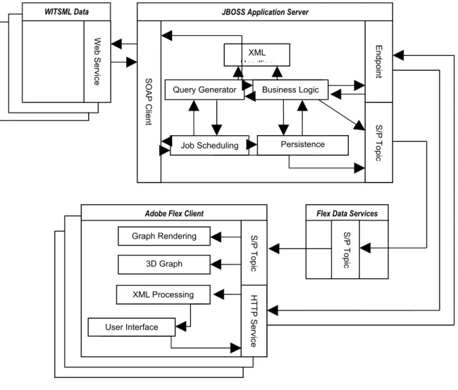
The system is divided into 4 main sections.
WITSML Data Source – A WITSML data source is a data server that allows a
web service to be used to interact with its published data. It will act as a source for all data (both static and real-time). This section will not be implemented for this project but is a requirement to feed the project data.
JBoss Application Server – This section contains all the main logic required for achieving the server requirements. The server will source, process, save and then forward all data from WITSML servers to the Adobe Flex client. It will implement all the requirements for the WITSML client and RIA interaction.
Flex Data Services – This section handles the interactive data services required
by the Adobe Flex client. As the client is based inside the browser it cannot easily maintain a Subscriber/Publisher connection and therefore needs this application to manage the connection for it.
Adobe Flex Client – This section handles the display of data inside the browser
that the user interacts with. The client runs inside the Flash plug-in and allows advanced features to be used to display and interact with the data.
Detailed System View depicts how the various sections link together. It also
encapsulates the main elements that will be included inside each section to fulfil the requirements stated. Each section will be broken down and discussed in the following section:
Figure 4.1 – A detailed system view.
1.13.1 JBoss Application Server
JBoss is a Java-based application server that provides a number of services. This system will use a number of these services as well as integrating other libraries to fulfil the server requirements. The server is made up of four key components.
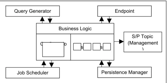
1. Business Logic Component – This component is the controlling element
inside the server and can be considered as the core of the server. It has direct access to all other components to be able to achieve any processing that the client may need. It is configured by an XML file that defines the functionality
Flex Data Services
S/P
Topic
Adobe Flex Client
S/P Topic Graph Rendering 3D Graph Rendering HTTP Service XML Processing User Interface Web Service WITSML Data Endpoint S/P Topic XML Handling Business Logic Persistence Manager Job Scheduling Query Generator SOAP Client
available and the configuration for all other components.
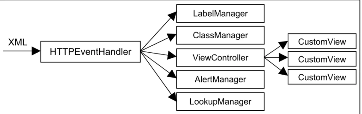
Figure 4.2 shows how this component interacts with other components in the system. The business logic component is directly linked to all the key
components of the system as it directly controls how they should interact with each other.
Figure 4.2 – A detailed diagram of the business logic component.
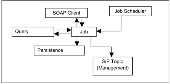
2. Job Scheduler Component – This component handles the management and
execution of jobs in the server. It has access to the Query Generator, SOAP Client, Persistence Manager and JMS Topic components. The main purpose of this component is to continuously execute jobs to capture data as it changes or is updated on a data server. Each job executed by the scheduler shares these components to be able to create a Subscriber/Publisher producer. This producer supplies data to a Subscriber/Publisher Topic to feed data in real-time to
subscribed Flex clients.
Figure 4.3 shows a breakdown of how this component uses the others to maintain up-to-date data. The job scheduler component manages job objects. Each job object has access to the SOAP client, query generator, persistence manager and S/P manager. This allows it to read data from a WITSML server,
Business Logic Configuratio
n Custom Classes
Query Generator Endpoint
S/P Topic (Management
)
Persistence Manager Job Scheduler
cache the value and then add it to a S/P topic.
Figure 4.3 – A detailed diagram of the job scheduler component.
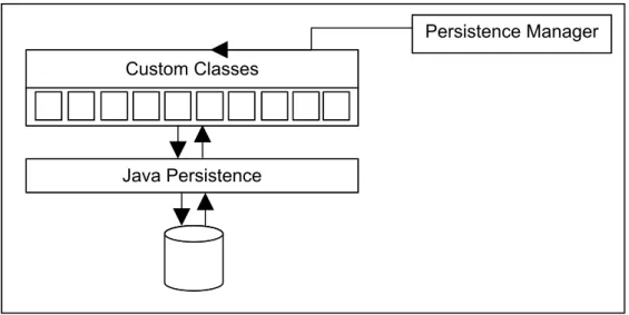
3. Persistence Manager Component – This component handles the loading
and saving of data between the system and a database. It uses the built-in functionality of JBoss with custom configured classes to save and reload data into Java objects.
Figure 4.4 shows the persistence manager structure used in the server. The majority of this component will rely on the database management code supplied by the JBoss application server. It provides facilities to map custom written Java classes to database tables. The persistence manager controls this
Query Generator Job Scheduler Job S/P Topic (Management) SOAP Client Persistence Manager
configuration to provides functions to load, save, update and delete records.
Figure 4.4 – A detailed diagram of the persistence component.
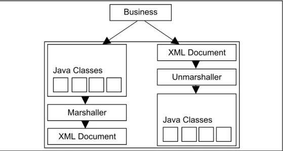
4. XML Handling Component – This component handles the processing of XML,
converting it between the required forms. As the system represents the majority of elements in XML, this component is needed to load and convert XML in set formats.
Figure 4.5 gives a breakdown of how this component functions. The component is broken into two main parts: a marshaller and unmarshaller. The unmarshaller handles the conversion between XML documents and Java classes. The
marshaller is the opposite of this and handles the conversion between the Java
Java Persistence Custom Classes
objects and an XML document.
Figure 4.5 – A detailed diagram of the XML handling component.
Java Classes Marshaller Unmarshaller Business Logic XML Document Java Classes XML Document
1.13.2 Flex Data Services
Flex Data Services (also known as LCDS) are an extendable implementation of web services that have been provided for a Flash-based language. These services have been written in Java and are configured using XML. Although the API is documented online, the Java implementation is not open-source. This means that if this project requires the web services to be customised it could be difficult to extend the existing code.
The main purpose of this section is to maintain and clean-up connections that are used to stream data between the server and client. It is a key element as it provides a data forwarding service to the Flex client and removes the complexity from the Flash component.
1.13.3 Adobe Flex Client
Adobe Flex is a Flash-based language that can be compiled into Flash movies to produce an RIA. The language comes with many additional libraries to help develop and use components required for a rich user interface. The language also includes a chart library that allows charts to be developed and customised dependent on the user’s requirements. This project will use a number of features available to create an RIA capable of fulfilling all of the client requirements. The client is made up of three main components.
1. User Interface – This component handles all of the displayable content that is
available to the user. It maintains the correct view of data and hides/shows component as different events are triggered.
The user interface will consist of a number of elements. These elements have been defined by the sponsoring company to evaluate selected features of the Flex language. The following components are required:
Menu System – A component is required to allow commands to be
invoked from a standard menu like interface. It would be preferential if the menu was similar to the standard GUI menu that is available in most applications. This allows users of the system to become easily familiar with it as they will have used similar applications.
3D Visualisation of Wellbore – A 3D component is required to be able to
render three dimensional coordinates of the trajectory of a Wellbore on the GUI. It needs to be able to change the perception of the component in order to view the rendering from different angles. It will also need to be updated in real-time
Knowledge Bubble – A component is required to expand on the details
displayed in the 3D visualisation. This component will contain a table like structure with data values related to a selection in the 3D visualisation.
Text Window – A component is required to give additional information
about the details display in the 3D visualisation and knowledge bubble. Unlike the knowledge bubble this component will contain more abstract data that is not directly related to the 3D visualisation.
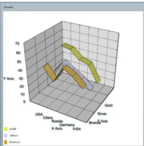
2D Representation of Drilling Parameters – A 2D graph component is required
to represent the status of drilling parameters while a wellbore is being drilled. This component needs to be updated in real-time by extracting two
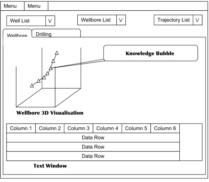
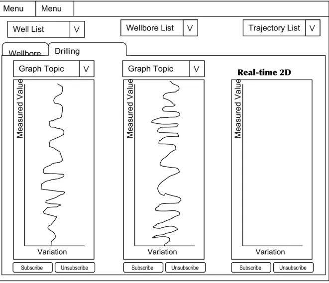
dimensional coordinates from data sent to it from the server. and Figure 4.7 depict a sample layout of the components required. Figure 4.6 shows a window with a menu at the top left corner. At the top of the window there are three selection boxes used to select which data the user requires to view. The main content of the screen is contained within a tabbed component, for this diagram the Wellbore tab is selected. The tab contains three of the components
required: the 3D graph, the knowledge bubble and the text window. Figure 4.7 shows the same window as Figure 4.6 but with the Drilling Parameters tab selected. This tab contains three 2D graphs with additional components that allow the name of a stream of data to be selected and buttons to start and stop the streaming of data.
Figure 4.6 – An example layout of the design elements required by the sponsoring company.
Menu Menu
Well List Wellbore List Trajectory List Drilling
Parameters Wellbore
Knowledge Bubble
Wellbore 3D Visualisation
Column 1 Column 2 Column 3 Column 4 Column 5 Column 6 Data Row
Data Row Data Row
Figure 4.7 – An example layout of the real-time data graphs required.
2. Graph Rendering – This component handles the streaming and filtering of
data passed from the Flex Data Services to the client. It maintains the data previously collected and processes any new data received. It is a requirement that the graphs are rendered in real-time therefore this component ensures the efficiency of the data processing and graph rendering.
3. XML Processing – This component handles the parsing and processing of
content received from the server. All data sent from the server is defined in a set XML format. This component extracts data from the XML document and populates the relevant user interface items. It handles items like lookup lists, menu items, static graph data and the content for labels.
Menu 1
Menu 2
Well List Wellbore List Trajectory List Wellbore Drilling Parameters Variation Measured Value Variation Measured Value Variation Measured Value Subscribe Unsubscribe
Graph Topic Graph Topic Real-time 2D
Graphs
Design Discussion
This section contains a discussion of the design options available to implement the requirements specified in the Section 1.10. It will evaluate the implementation possibilities and decide on the best solution to fulfil the requirements.
1.14Server Design
As the server will be based in JBoss the available features of the application server will be used to reduce the implementation of additional components.
1.14.1 RIA Interaction Design
5.1.1.1Server Communication
Requirement 1.11.1 of the RIA Interaction requires a web-enabled access point to be created. In order to achieve this, three points must be satisfied; these points are described in the following list.
1. Publish Java classes so they can be accessed by a URL.
As this project will use a web-container to publish classes, the design needed for this requirement is minimal. It can be met by creating and deploying a custom servlet to interact with the RIA client.
2. Create a generic interface so that the RIA can interact with the server.
The JBoss naming service will be integrated into the business logic to give the RIA client information about which class to invoke when it needs different types of data. Using a Java interface, a standard method will be applied to all classes that could be invoked. This will allow a generic interface to be created inside the deployed servlet.
3. Connect the published Java code to the business logic in the project.
This requirement is heavily linked to the generic interface mentioned in the previous functional requirement. The business logic in the core of the project will contain a mapping of classes that the client can use to perform different
actions on the server. When a client first initialises it will need to receive the mapping so that it has the information to make further calls. When a client requires an action to be performed it will invoke a call to the server that contains the name and method of the class that will do the work. The servlet uses this information to lookup the class using the naming system and invokes a standard method to beginning the processing.
Requirement 3 of the RIA Interaction requires a real-time data interface to be created. A managing class that will wrap around the JBossMQ component will be implemented to fulfil this requirement. The managing class will provide the following features.
1. Provide the ability to publish and remove topics.
The server will need to create and destroy topics as they are required by the client. The managing class must provide methods to allow topics to be added and removed from business logic classes.
Topic Management
Topics must have unique names to identify them and allow them to be deployed on the server. Each topic will be published by using the unique identifier of the WITSML object that the real-time data stream is coming from. When multiple topics are linked to the same WITSML object but use a different field, the unique identifier will also contain the name of the field. Memory Management
The server implementation must monitor the published streams and the number of clients connected to ensure that unused data streams are removed from the server. This is an important factor as potentially large quantities of data could be received and if this data is not being used by any clients, it is wasting the resources of the server.
2. Provide the ability to have multiple connections to the same topic
same topic. By using this technology this requirement will be satisfied without having to implement further code.
5.1.1.2Exchanging XML data with the client
XML is a highly configurable language that allows a variety of types of data to be represented within it. This project requires data to be represented in a structured manner so that the client can easily extract it and populate elements on screen. The XML structure will be based around the data requirements of the client and be created through the implementation of an XML schema.
XML Structure
The XML structure must include the following elements.
1. The ability to represent data for a specific section of each client view.
The viewable content will be split up in regards to the screen it is displayed in. The top level element will group all the viewable content under a views tag. This tag will contain multiple view child tags, each one representing a single screen. A view tag can contain data about any possible element displayed on that screen. A tab tag will be added to the view tag to represent a grouping of elements and can contain multiple element tags. Each individual element on screen will be represented within an element tag that will contain the data required to render this element onscreen.
Code Fragment 5.6 gives an example of the XML structure described above. This XML fragment describes a single screen with two tab elements contained within it. Each tab also contains child elements which in turn contain data about those elements.
<views>
<view id="mainView"> <tab name="wellbore">
<element id="wellbore-graph" type="graph"> ...
</element>
<element id="traj-details" type="table"> ...
</element> </tab>
<tab name="drill-params">
<element id="drill-params-graph" type="graph"> ...
</element> </tab>
</view> </views>
Code Fragment 5.6 – An example XML document that represents data for elements onscreen
2. The ability to represent lists of data.
The client requires lists of data to be able to populate drop-down menus and check-box lists. A simple model can be used to represent this data. A
lookupLists tag can be used to group all the lists. This tag contains multiple lookupList tags, each one representing a single list. A lookupList can contain many lookupItem tags. The lookupItem tag is designed to be able to retain a displayable value and a key. This is the typical structure required by an onscreen list element as the user requires a readable value and the system requires a key to process the selection.
Code Fragment 5.7 gives an example of the XML structure described above. This XML describes two lookup lists: one contains items relating to a well and the other relating to wellbores. Each list contains a number of data items. Each data item contains a label attribute for display purposes and a value attribute for the key required by the application.
<lookupLists>
<lookupList id="wells">
<lookupItem label="Test Well 1" value="well.uid1"/> <lookupItem label="Test Well 2" value="well.uid2"/> </lookupList>
<lookupList id="wellbore-well.uid1">
<lookupItem label="Wellbore 1" value="wellbore.uid1"/> <lookupItem label="Wellbore 2" value="wellbore.uid2"/> <lookupItem label="Wellbore 3" value="wellbore.uid3"/> </lookupList>
</lookupLists>
Code Fragment 5.7 – An example XML document that represents lookup lists
3. The ability to represent tables of data.
The client requires tables of data to be represented within the XML. Typical tables consist of column headers and rows of data, each row containing
relevant data to its header. This will be represented in the XML by splitting the data into a header and data section. As a table will be an element on screen it will be represented by the element tag with the type attribute set to “table”. The table element will contain two child tags; a labels tag and a data-items tag. Data-labels represent the header information required for the columns. It will contain a text attribute for the name of column and a linked data-field so that a data item property can be matched to correct column. Data-items represent the data section of this element. This tag can contain multiple data-item tags where each tag represents a row of data for the table. A data-item can contain multiple property tags. Each property tag represents a single cell in the table. It contains a name attribute that allows the property to be matched to the data-field in the header and a value attribute that contains the value that the cell should contain.
Code Fragment 5.8 gives an example XML of the table structure. This XML describes a table of well-site data. It contains five headings and two rows. It is clear from this figure which columns the data properties match to and would be a simple matter for the RIA client to parse this data.
<element id="traj-details" type="table"> <data-labels>
<data-label text="Md" datafield="md"/> <data-label text="Tvd" datafield="tvd"/>
<data-label text="Record Time" datafield="dTimStn"/> <data-label text="Incl" datafield="incl"/>
<data-label text="Azi" datafield="azi"/> </data-labels>
<data-items>
<data-item name="Station 1">
<property name="md" value="200"/> <property name="tvd" value="300"/>
<property name="dTimStn" value="2007-07-01 10:30"/> <property name="incl" value="20"/>
<property name="azi" value="30"/> </data-item>
<data-item name="Station 2">
<property name="md" value="400"/> <property name="tvd" value="500"/>
<property name="dTimStn" value="2007-07-01 10:45"/> <property name="incl" value="40"/>
<property name="azi" value="70"/> </data-item>
<data-items> </element>
Code Fragment 5.8 – An example XML document that represents table data
4. The ability to represent labels of onscreen elements.
This requirement stems from the idea of the internationalisation of the application. If the client was designed with a defined interface in a single language, with the labels hard-coded into the application, it would make client company customisation and language translations extremely difficult. The main way to solve this problem is to leave the label population until the runtime of the application. This requires the server to supply a list of labels when a client first connects so that the client can populate its screen. The XML required to encapsulate this data will be quite simple as only a small amount of data is required. The XML will consist of a main “labels” tag and multiple “label” tags. The labels tag is the grouping element that contains a list of all the individual labels onscreen. Each label tag represents a single label on screen and contains two attributes; the key and value.
The key attribute is made of the ID’s of elements used in the RIA client.
key="<view-id>.<element-id>"
The section before the “.” is the ID of the view that the label is located in and the section after is the ID of the element that the label should be applied to. This allows the XML processing unit in the RIA client to find the element and update its label accordingly. The value attribute is the actual value that should be displayed in the label.
Code Fragment 5.9 gives an example XML of a labels excerpt. This XML describes the labels required for the login screen.
<labels>
<label key="login.message" value="Welcome, please login"/> <label key="login.username" value="Username"/>
<label key="login.password" value="Password"/> <label key="login.loginbutton" value="Login"/> </labels>
Code Fragment 5.9 – An example XML document that represents onscreen labels
5.1.1.3Handling Extendibility
The nature of client development adds the requirement to cater for the ever changing needs of a client. XML was chosen as the data interchange language because it can be easily updated to allow future development and basically solves this need. However, this requirement is also tightly coupled to the XML processing in the application as the server must be able to cater for updates and changes without breaking the server or client XML processing. In order to achieve efficient processing coupled with the
extendibility required, it would be beneficial to use technology that could be reused as the XML requirements change. Using JAXB, Java code can be automatically generated from an XML schema allowing new code to be created each time new requirements are added to the system.
System Core Extendibility
The core of the system will use an XML configuration file to define the business logic and allow updates and new features to be applied easily. It also allows custom end user configuration to be applied without any changes to the application code. The business logic will consist of three main parts; the configuration, services and query types. The configuration section will consist of the linkage elements required to setup the server and to interact with a client. The services section will include all the
available WITSML servers that the system is setup to interact with. The query types section will define the different types of WITSML query that can be applied to a WITSML server. These queries will be used to check if new real-time is available and will contain parameters to be able to extract real-time data.
The server configuration will need to include the following elements.
Identity – This section will define the details about the server. It will include
assigned to the server and the current version number. It will be used to initialise the server and to supply identity information to the Flex client.
UID-mapping – This section will help process WITSML documents by creating a
mapping between the WITSML object names and the field that uniquely identifies the object. It will be used by WITSML processing classes to help unique identifier recognition in WITSML queries.
Class-mapping – This section defines the linkage between a WITSML object
name and the Java class that represents it. It will be used by WITSML
processing classes to help convert WITSML documents between XML and Java.
Client-mapping – This section defines a mapping of the JBoss session beans
available for a client to invoke. It maps the bean to an ID that will be hard-coded into the Flex client. This allows server processing to be changed by altering the bean that an ID is mapped to without having to alter the client. By using this approach the system will be easier to maintain as it decouples the client executions from the server classes.
As this project centres on retrieving and viewing data, the data sources must be defined in the configuration. This allows a connection to be established to other
WITSML servers and data to be extracted. This section will need to define the address and authentication details of an endpoint as well as a user-friendly vendor name and the type of query required by the client. This definition is depicted in Code Fragment 5.10.
<services>
<service vendor="IDS Test Site" username="idsadmin" password="idsadmin" queryType="DepthBased">
http://192.168.1.69:8080/rtv_source/services/WMLS </service>
</services>
Code Fragment 5.10 – An example xml document of defined services
The server must define the type of query required for the services available. As the API of WITSML does not define a standard method of querying for updated data, it means that companies may choose to implement different solutions to this problem. The different implementation defined in this XML document will be researched from
companies who use the standard to gain an insight into how real-time WITSML updates are performed in the industry.
The structure of the query types will be based around the information required by the system to query a WITSML Server. Code Fragment 5.11 gives an example of this structure. It will include many query-type tags where each one defines the setup required for a company. It will also include mappings to JBoss session beans to allow easy reconfiguration of the query.
<query-types> <query-type name="DepthBased"> <query-object witsmlname="trajectory"> <queryTypeClass>TrajDepthQuery</queryTypeClass> <customQuery>JMSTrajectory</customQuery> <resultProcessor>TrajectoryResultProcessor</resultProcessor> <interval>60</interval>
<conditional-field name="mdMx" type="Increase"/> </query-object> <query-object witsmlname="log"> <queryTypeClass>LogDepthQuery</queryTypeClass> <customQuery>JMSLog</customQuery> <resultProcessor>LogResultProcessor</resultProcessor> <interval>4</interval>
<conditional-field name="endIndex" type="Increase"/> </query-object>
</query-type> </query-types>
Code Fragment 5.11 – An example XML document of a query type
1.14.2 WITSML Client Design
5.1.1.4WITSML Query Handling
The WITSML query language is capable of querying a large set of WITSML objects. In order to encapsulate a number of these objects, a Java interface will be created to represent the functionality required by a generic WITSML object query. This will create a base design that can be extended in multiple Java classes. These classes will
represent a query interface for each type of object and fulfil Requirement 1 of the WITSML Client requirements.
WITSML Query Interface
The interface will provide methods to produce queries from the following types of parameters.
Single parameter – The unique identifier of the object can be used as a
parameter to be able to create a query for a specific object. This requires a mapping of the UID field name for each object to be stored in the configuration so the correct field can be set with the value. This field name can then be matched with the UID value and used to create the query.
Multiple parameters – Parameters will be placed in a map data structure that
will contain the name of the field as the key and the value of the field as the value. This allows fields in a query to be populated according to its name. It also introduces a limitation on the parameters as field names are not unique within WITSML queries and specifying a field name does not define which object it is attached to. In order to resolve this problem, another method will be added to support a custom query object. This object will contain the name of the fields to populate, the values to populate and the child objects required. Child objects will be represented by the same custom query object as its parent to allow a reusable structure.
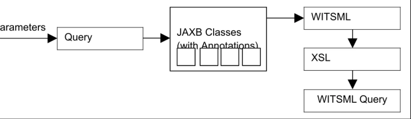
WITSML Query Generation
WITSML queries follow the same structure as the documents that represent the data. This fact can be exploited when designing a query generator as the data object can be used as a template for the query. As the project is using the JAXB it will automatically generate Java classes that represent the WITSML data objects. The generated classes contain Java 5 annotations. Code Fragment 5.12 shows an example of an annotation that marks the class attribute name as a required XML element. This assignment
originates from the schema as the XML elemen