Design and Manufacture of Engineered
Titanium-based Materials for Biomedical
Applications
by
Fares Almushref
Wolfson School of Mechanical, Electrical and Manufacturing
Engineering
Loughborough University
A Doctoral thesis submitted in partial fulfilment of the
requirements for the award of Doctor of Philosophy
March 2017
Abstract
ii
Abstract
Metallic materials have gained much attention recently from the areas of medical devices and orthopaedics. Artificial organs, dental implants, prostheses and implants that replace damaged or malfunctioning parts in the body are, or contain, metal components. Our ageing society poses an increased demand to provide devices and implants that can demonstrate better performance than those presented by traditional solutions. Matching the mechanical properties (i.e. stiffness and strength) of the device to those of the host tissue is a major challenge for the design and manufacture of engineered metal materials for biomedical applications. Failure in doing so provokes implant loosening, patient discomfort and repeated surgeries. Therefore, tailoring physical properties and biocompatibility of those materials is the main final aim of this research programme.
This PhD study has focused on the tailoring of the mechanical properties of titanium-based materials and titanium-titanium-based alloys. Titanium inertness and the selection of biocompatible alloying elements were set as the baseline. Two approaches were employed to decrease stiffness (i.e. Young’s modulus): one, by introducing porosity in a titanium matrix and therefore, reduce its Young’s modulus, and two, by designing and manufacturing beta-titanium-based alloys with a reduced Young’s modulus. Titanium scaffolds were manufactured using powder metallurgy with space holder technique and a sintering process. Different space holder sizes were used in four different categories to study the effect of pore size and porosity on the mechanical properties of the porosity engineered Ti scaffolds. Ti-based alloys were manufactured using manufacturing techniques such as sintering and arc-melting. The effect of different fabrication processes and the addition of beta-stabilising elements were studied and investigated.
The obtained results of mechanical properties for pore size and porosity were within the values that match bone properties. This means these materials are suitable for biomedical application and the beta-Ti alloys results show that the mechanical properties can be decreased via tailoring the crystal structures. The characterisation of the Ti-based alloys helps to develop this material for its use in biomedical application.
Acknowledgment
iii
Acknowledgment
First and foremost, I thank almighty Allah (God) for giving me the ability and patience and blessing me with success to complete this thesis.
I would like gratefully to thank my academic supervisor, Dr Carmen Torres-Sanchez; it is truly a pleasure working with her for her unlimited support, continuous encouragement and durable patience during my project. Because of her close supervision and great knowledge and professionalism I have experienced a significant event in my life with a positive effect to a promising future.
The Financial support provided by Saudi Arabia government represented in Royal Commission for Jubail and Yanbu Project, and my department Jubail Industrial College include the general manager Dr Ali Asseri. Also special thanks for support people in Human Resource development Department for their support. Also special thanks for Saudi Cultural Bureau in London for their continuous support and advisory specially my supervisor Adel Boukerci.
Appreciation and gratitude for many of the people whom always helped and support within Wolfson School of Mechanical, Electrical and Manufacturing Engineering include Simon Neal and Robert Temple and many other people I cannot mention all their names and people from outside school include Loughborough Material Characterization Centre, for their help and support.
Finally, special thanks to my parents brothers and sisters whom always they support me and worry about me no matter how old I am, they keep contact me and encourage me while I am far away from them. I do not forget my lovely wife and my children for their patience, time and understanding. They spent days and nights without seeing me at home so thanks a lot, you guys.
List of Publications
iv
List of Publications
Fares Almushref, Dr Carmen Torres-Sánchez : “Influence of Fe Contamination on Ti-35Nb-4Sn alloy Phase Transformation’’, Wolfson School of Mechanical, Electrical and Manufacturing Engineering, PHD Research Conference, 14th-15th June 2016, Loughborough, United Kingdom.
Fares Almushref, Dr Carmen Torres-Sánchez: “Effect of Microstructure on Mechanical Properties for Ti Scaffolds’’, FEMS Junior Euromat Conference 2016, 10th -14th July 2016, Lausanne, Switzerland.
C. Torres-Sánchez, F.R.A. Almushref, M. Norrito, K. Yendall, Y.Liu, P.P. Conway: “The effect of pore size and porosity on mechanical properties and biological response of porous titanium scaffolds’’, Mat & Eng Sci C, submitted.
Table of Contents v
Table of Contents
Abstract ... ii Acknowledgment ... iii List of Publications ... iv Table of Contents... vList of Tables ... viii
List of Figures ... ix
Nomenclature and Symbols ... xiv
Chapter 1 Introduction... 1
1.1 Background ... 1
1.2 Bone Structure and Mechanical Properties ... 3
1.2.1 Bone Structure ... 3
1.2.2 Bone Mechanical Properties... 3
1.3 Biomimetic Ti-based Scaffolds ... 4
1.3.1 Porous Ti Materials. ... 4
1.3.2 Ti-based alloys with β-phase structure at room temperature. ... 5
1.4 Objective of This Study ... 5
1.5 Project Plan and Methodology ... 6
1.6 Contribution to Knowledge ... 7
Chapter 2 Literature Review ... 8
2.1 Introduction ... 8
2.2 Titanium and its Alloying Elements ... 8
2.3 Titanium –Based Alloys and Their Applications Orthopaedic and Medical Devices ... 15
2.4 Martensitic Phase Transformation ... 16
2.5 Manufacturing Techniques for Titanium and Titanium Based Alloys ... 18
2.5.1 Powder Metallurgy Technique (PM) ... 18
2.5.2 Arc-Melting ... 20
2.6 Manufacturing Techniques for Porous Ti and Ti-Alloys ... 22
Table of Contents
vi
2.6.2 Powder Metallurgy with Space-Holder ... 23
2.6.3 Replica Technique for Porous Materials ... 31
2.6.4 Additive Manufacturing Technique ... 31
Chapter 3 Experimental Procedure ... 33
3.1 Introduction ... 33
3.2 Manufacturing Protocols... 33
3.2.1 Porous Titanium Scaffolds ... 33
3.2.1.1 Green Sample Fabrication ... 34
3.2.1.2 Space Holder Removal via Calcination Process ... 38
3.2.2 Sintering Process ... 38
3.2.2.1 Sintered Titanium-based alloys ... 40
3.2.3 Arc-Melting Process ... 41
3.2.4 Thermal Treatments ... 42
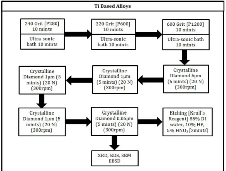
3.2.5 Polishing Protocol ... 44
3.3 Characterisation Process and Analytical Techniques ... 47
3.3.1 Introduction ... 47
3.3.2 Chemical Analytical Techniques ... 47
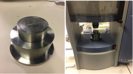
3.3.3 Mechanical Testing ... 55
3.4 Software ... 60
3.5 Statistical Analysis ... 60
Chapter 4 Engineered Porosity Titanium Scaffolds ... 61
4.1 Introduction ... 61
4.2 Microstructure Characterisation ... 61
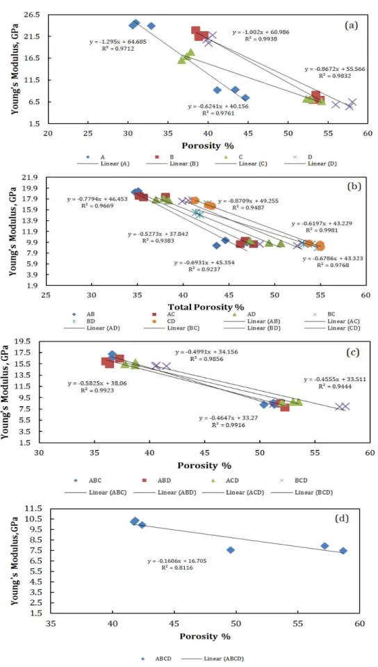
4.3 Mechanical Properties of Ti Scaffolds ... 83
Chapter 5 The influence of the Manufacturing Process for Low Stiffness Ti-Based Alloys ... 87
5.1 Introduction ... 87
5.2 Results and Observations ... 87
5.2.1 Arc-melted Ti-35Nb-4Sn Results ... 87
5.2.2 Sintered Ti-35Nb-4Sn Results... 95
Chapter 6 Titanium Based Alloys ... 107
Introduction ... 107
Ti-based Alloys Characterisation ... 110
Table of Contents vii 6.2.2 Ti-7Mo-7Sn ... 112 6.2.3 Ti-7Mo-15Sn ... 114 6.2.4 Ti-35Nb-4Sn ... 116 6.2.5 Ti-35Ta ... 118 6.2.6 Ti-35Ta-7Sn ... 120
Effect of Heat-treatment and Deformation on Ti-based Alloys ... 122
6.3.1 Ti-35Nb-4Sn ... 123 6.3.2 Ti-35Nb-14Ta ... 127 6.3.3 Ti-49.7Nb-4.8Sn ... 131 6.3.4 Ti-65Ta-7Mo ... 135 6.3.5 Ti-7Mo-5Sn ... 139 6.4 Summary ... 142 Chapter 7 Discussion ... 144 7.1 Introduction ... 144
7.2 Engineered Porosity Titanium Scaffolds ... 144
7.3 The influence of the manufacturing process for low stiffness Ti based alloys 146 7.4 Titanium Based Alloys ... 149
Chapter 8 Conclusion ... 153
Chapter 9 Future Work ... 156
viii
List of Tables
Table Page
Table 1-1: Different types of bone (14). ... 3
Table 1-2: Bones Mechanical properties (14). ... 4
Table 2-1: Titanium characteristics compared with other elements(18). ... 10
Table 2-2: Titanium alloys for biomedical applications (1,25). ... 16
Table 2-3:Different alloys prepared with ball milling. ... 19
Table 2-4: Ti-alloys fabricated by arc-melting method. ... 21
Table 2-5: Different space holder and their removal techniques. ... 26
Table 2-6: Different SMAs with different heat-treatment. ... 30
Table 3-1: Samples fabricated for each group. ... 35
Table 3-2: Ti-35Nb-4Sn elemental infromation. ... 41
Table 4-1: Average pore sizes from Originlab software. ... 75
Table 4-2: Samples with nominal 55% porosity measurement using ImageJ and Archimedes measurement. ... 78
Table 4-4: Two Samples with 70% porosity measurement from ImageJ from professional camera images for whole surface for inernale surface sliced . ... 78
Table 5-1: Mechanical Testing results for Ti-35Nb-4Sn alloy. ... 106
Table 6-1: Ti-alloys with different structure. ... 109
Table 6-2: Cold rolled samples behaviour during rolling process. ... 122
ix
List of Figures
Figure Page
Figure 1-1: Tissue Engineering (5). ... 2
Figure 1-2: Bone ingrowth within implant scaffolds (16). ... 5
Figure 2-1: Cell crystal structure both alphe and beta phase(18). ... 9
Figure 2-2: Phase diagram of Ti (19,20). ... 9
Figure 2-3: Different alloying elements and their effect on titanium alloy phase(18). ... 10
Figure 2-4: Gibbs free energy for austenie and martensite(31). ... 17
Figure 2-5: Thermal phase trasnformation path. ... 18
Figure 2-6: Powder particls crushed between milling balls (32) ... 19
Figure 2-7: Various manufacturing techniques of porous metal (2). ... 22
Figure 2-8: Fabrication Process for Titanium foams (53) ... 24
Figure 2-9: Foam containing macropores.(54). ... 24
Figure 2-10: Statistical analysis of pore size and distribution (33). ... 26
Figure 2-11: Optical micrographs of cross section of porous TiNi SMAs fabricated by ... 27
Figure 2-12: Recoverable and irrecoverable strains (67). ... 27
Figure 2-13: Compressive stress-strain Curve (68). ... 28
Figure 2-14: Compression testing of Ti-Nb-Zr (a) as sintered (b) annealed at 450 °C (c) annealed at 600 °C(8). ... 29
Figure 2-15: Liquid metal is casted around granules (2). ... 31
Figure 3-1: Flow diagram of fabrication process ... 33
Figure 3-2: Schematic diagram for particle size distribution. ... 35
Figure 3-3: Schematic of moulding process. ... 37
Figure 3-4: Steel die and Atlas 40 to fabricate green samples and die are placed in instron machine to start compacting process. ... 38
Figure 3-5: Particles bonding during sintering process (74). ... 39
Figure 3-6: Sintering tube furnace connected to a vacuum pump. ... 39
Figure 3-7: Typical Sintering-Time Profile. ... 40
Figure 3-8: Arc-melting furnace. ... 42
Figure 3-9: Encapsulated 3mm, and 10mm samples in quartz tub. ... 43
Figure 3-10: Schematic diagram for sample capsulizing and quenching process. ... 44
List of Figures
x
Figure 3-12: Polishing Procedure for Ti porous samples. ... 45
Figure 3-13: Polishing procedure for sintered Ti and Ti-based alloys samples. ... 46
Figure 3-14: Polishing procedure for arc-melted Ti and Ti-based alloys samples. ... 46
Figure 3-15: Typical DSC Graph for a Ti-based alloy. ... 48
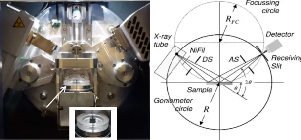
Figure 3-16: Visualization of Bragg Equation (76). ... 49
Figure 3-17: Schematic representation of θ/2θ diffraction in Bragg-Brentano geometry (76) and a photo of 2D Phaser used in this project. ... 50
Figure 3-18: XRD of β Ti and β+α Ti alloys. ... 51
Figure 3-19: EDS Principle. ... 52
Figure 3-20: Inserting sample to EDS machine... 53
Figure 3-21: (a) Nikon Optiphoto microscope,(b)Alicona InfiniteFocus System. ... 54
Figure 3-22: ImageJ interface. ... 55
Figure 3-23: Steps to performe images analysis using ImageJ. ... 55
Figure 3-24: Schematic Diagram of Mechanical Testing. ... 57
Figure 3-25: Nanoindentation machine setup. ... 58
Figure 3-26: (a) Load vs displacement curve,(b) indenter pattern on sample surface... 59
Figure 3-27: Indents in cast iron. ... 59
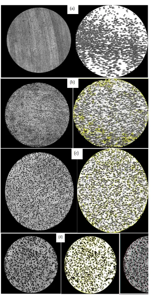
Figure 4-1: Pores size and distribution for nominal 55% scaffolds (a)45-106µm (b)106-212µm (c)212-300µm and (d) 300-500µm. ... 61
Figure 4-2: Pores size and distribution for nominal 70% scaffolds (a)45-106µm (b)106-212µm (c)212-300µm and (d) 300-500µm. ... 62
Figure 4-3: Pores size and distribution for nominal 55% scaffolds (a)45-106µm, 106-212µm (b) 45-106µm, 212-300µm (c) 45-106µm 300-500µm (d) 106-106-212µm, 212-300µm (e) 106-212µm, 300-500µm and (F) 212-300µm, 300-500µm. ... 63
Figure 4-4: Pores size and distribution for nominal 70% scaffolds (a)45-106µm, 106-212µm (b) 45-106µm, 300µm (c) 45-106µm, 300-500µm (d) 106-106-212µm, 212-300µm (e) 106-212µm, 300-500µm and (F) 212-212-300µm, 300-500µm. ... 64
Figure 4-5: Pores size and distribution for nominal 55% scaffolds (a)45-106µm, 106-212µm, 212-300µm (b) 45-106µm, 106-212 µm, 300-500µm (c) 45-106µm, 212-300µm, 300-500µm and (d) 106-212 µm, 212-300µm, 300-500µm. ... 65
Figure 4-6: Pores size and distribution for nominal 70% scaffolds (a)45-106µm, 106-212µm, 212-300µm (b) 45-106µm, 106-212 µm, 300-500µm (c) 45-106µm, 212-300µm, 300-500µm and (d) 106-212 µm, 212-300µm, 300-500µm. ... 65
Figure 4-7: Pores size and distribution for scaffolds nominal 55% (a)45-106µm, 106-212µm, 212-300µm, 300-500µm, nominal 70% (b) 45-106µm, 106-106-212µm, 212-300µm, 300-500µm. ... 66
List of Figures
xi
Figure 4-8: Pores size distribution for nominal 55% scaffolds (a) 45-106µm, (b) 106-212µm, (c) 212-300µm and (d) 300-500µm, (e) 45-106µm, 106-212µm (f) 45-106µm, 212-300µm (g) 45-106µm 500µm (h) 106-212µm, 212-300µm (i) 106-212µm, 300-500µm (j) 212-300µm, 300-300-500µm, (k) 106µm, 106-212µm, 212-300µm, (l) 45-106µm, 212µm, 300-500µm (m) 45-45-106µm, 212-300µm , 300-500µm (n) 106-212µm, 212-300µm, 300-500µm (o) 45-106µm, 106-106-212µm, 212-300µm, 300-500µm. 70 Figure 4-9 Pores size distribution for nominal 70% porosity scaffolds (a) 45-106µm, (b) 106-212µm, (c) 212-300µm and (d) 300-500µm, (e) 45-106µm, 106-212µm (f) 45-106µm, 212-300µm (g) 45-106µm 500µm (h) 106-212µm, 212-300µm (i) 106-212µm, 300-500µm (j) 212-300µm, 300-300-500µm, (k) 106µm, 106-212µm, 212-300µm, (l) 45-106µm, 212µm, 300-500µm (m) 45-45-106µm, 212-300µm , 300-500µm (n) 106-212µm, 212-300µm, 300-500µm (o) 45-106µm, 106-106-212µm, 212-300µm, 300-500µm.: 74 Figure 4-10: Pores size and count measurement using the Imagej algorithm on nominal 55% scaffolds (a) 45-106µm, (b) 106-212µm, (c) 212-300µm and (d) 300-500µm, ... 76 Figure 4-11: Pores size and count measurement using the Imagej algorithm on nominal 70% scaffolds (a) 45-106µm, (b) 106-212µm, (c) 212-300µm and (d) 300-500µm, ... 77 Figure 4-12: Pores size and area measurement using Imagej software and images obtained by professional camera for Sample (5) 70% (106-212 µm). ... 79 Figure 4-13: Pores size and area measurement using Imagej software and images obtained by professional camera for Sample (8) 70% (212-300 µm). ... 80 Figure 4-14: EDS results for scaffolds 70% porosity (a) 45-106µm, (b) 106-212µm, (c) 212-300µm and (d) 300-500µm. ... 81 Figure 4-15: EDS results for scaffolds 70% porosity (a) 45-106µm, (b) 106-212µm, (c) 212-300µm and (d) 300-500µm, ... 82 Figure 4-16: Compressive Strength of the Ti scaffolds (a) for 55% porosity samples all different sizes groups (b) for 55% porosity samples all different sizes groups. ... 83 Figure 4-17: Youn’sg modulus of the Ti scaffolds for various pores sizes and for both 55% and 70% porosity samples (a) Single Pore size, (b) Double pore size, (c) Triple pore size and (d) Random pore size group. ... 84 Figure 4-18: Young modulus of the Ti scaffolds to compare both 55% and 70% porosity samples (a) Single Pore size, (b) Two different pore size, (c) three different pore size and (d) app pore size group. ... 86 Figure 5-1: DSC for arc-melted Ti-35Nb-4Sn (a) without quenching (b)with quenching. 88 Figure 5-2: EDS for arc-melted Ti-35Nb-4Sn without quenching. ... 90 Figure 5-3: EDS for arc-melted Ti-35Nb-4Sn with quenching. ... 92 Figure 5-4: XRD Compare between arc-melted Ti-35Nb-4Sn before quenching and after quenching. ... 94 Figure 5-5:DSC results for Sintered Ti-35Nb-4Sn sample: (a) not quenched, (b) quenched from 500ᵒC, (c)quenched from 1200ᵒC. ... 96
List of Figures
xii
Figure 5-6: EDS results for Sintered Ti-35Nb-4Sn without quenching. ... 99
Figure 5-7: EDS results for Sintered Ti-35Nb-4Sn with quenching. ... 101
Figure 5-8: XRD Comparison between sintered Ti-35Nb-4Sn before heat-treatment and quenching and after. ... 102
Figure 5-9: Mechanical Testing results (a)Arc-melted 4Sn,(b) Sintered Ti-35Nb-4Sn. ... 104
Figure 5-11: Nanoindentation for arc-melted Ti-35Nb-4Sn before and after quenching. 105 Figure 5-12: Nanoindentation for arc-melted Ti-35Nb-4Sn before and after quenching. 105 Figure 6-1: - Diagram with the attempted alloys in this study. ... 108
Figure 6-2: XRD for Ti-7Mo. ... 110
Figure 6-3: Nanoindentation for Ti-7Mo. ... 110
Figure 6-4: XRD for Ti-7Mo-7Sn. ... 112
Figure 6-5: Nanoindentation for Ti-7Mo-7Sn. ... 112
Figure 6-6: XRD for Ti-7Mo-15Sn. ... 114
Figure 6-7: Nanoindentation for Ti-7Mo-15Sn. ... 114
Figure 6-8: XRD for Ti-35Nb-4Sn. ... 116
Figure 6-9: Nanoindentation for Ti-35Nb-4Sn. ... 116
Figure 6-10: XRD for Ti-35Ta. ... 118
Figure 6-11: Nanoindentation for Ti-35Ta. ... 118
Figure 6-12: XRD for Ti-35Ta-7Sn. ... 120
Figure 6-13: Nanoinentation for Ti-35Ta-7Sn. ... 120
Figure 6-14: XRD result for Ti-35Nb-4Sn before (BH) and after heat-treatment (AH). 123 Figure 6-15: Images and SEM scans for Ti-35Nb-4Sn large grains. ... 124
Figure 6-16: Images and SEM scans for Ti-35Nb-4Sn small grains. ... 124
Figure 6-17: EDS result for Ti-35Nb-4Sn large grains and small grains. ... 125
Figure 6-18: Nanoindentation for Ti-35Nb-4Sn. ... 126
Figure 6-19: XRD for Ti-35Nb-14Ta before and after heat-treatment. ... 127
Figure 6-20: Images and SEM scans for Ti-35Nb-14Ta large grains. ... 128
Figure 6-21: Images and SEM scans for Ti-35Nb-14Ta small grains. ... 128
Figure 6-22: EDS for Ti-35Nb-14Ta large grain and small grain. ... 129
Figure 6-23: Nanoindentation for Ti-35Nb-14Ta. ... 130
Figure 6-24: XRD for Ti-49.7Nb-4.8Sn before and after heat-treatment.. ... 131
List of Figures
xiii
Figure 6-26: Images and SEM scans for Ti-49.7Nb-4.8Sn small grains. ... 132
Figure 6-27: EDS for Ti-49.7Nb-4.8Sn large grain and small grain. ... 133
Figure 6-28: Nanindentation for Ti-49.7Nb-4.8Sn. ... 134
Figure 6-29: XRD for Ti-65Ta- before and after heat-treatment.. ... 135
Figure 6-30: Images and SEM scans for Ti-65Ta-7Mo large grains. ... 136
Figure 6-31: Images and SEM scans for Ti-65Ta-7Mo small grains. ... 136
Figure 6-32: EDS for Ti-65Ta-7Mo large grain and small grain. ... 137
Figure 6-33: Nanoindentaion for Ti-65Ta-7Mo. ... 138
Figure 6-34: XRD for Ti-7Mo-5Sn. ... 139
Figure 6-35: Images and SEM scans for Ti-7Mo-5Sn. ... 140
Figure 6-36: EDS for Ti-7Mo-5Sn. ... 140
Figure 6-37: Nanoindentaion for Ti-7Mo-5Sn. ... 141
Figure 7-1: Sn conetent effect on elastic modulus and microhardness. ... 150
Nomenclature and Symbols
xiv
Nomenclature and Symbols
EDS Energy Dispersive X-ray Spectrometry Elastic modulus of the material
PCA Process Control Agent Elastic modulus of the indenter
UTM Universal Testing Machine Poisson ratios of the material
SMAs Shape Memory Alloys Poisson ratios of the indenter
XRD X-Ray Diffraction
BCC Body-centred cubic structure Weight of dry sample
HCP Hexagonal closed-packed structure Calculated weight using volume FCC Face-centred cubic structure SA Stearic Acid
CS Conventional sintering EBS Ethylene-Bis-Stearamide
CF-HIP
Capsule free hot isostatic pressing SHS Self-propagating high temperature
synthesis α Alpha phase β Beta Phase V Sample volume r Sample radius h Sample height M Mass Density SA Stearic acid Diameter Stress Force Cross-sectional area Strain Original length ∆ Change in length Original length Gm Martensite phase GA Austenite phase
∆ Gibbs free energy equation xc Average pore size
σ Standard deviation
Integer representing the diffraction order
Wavelength of the illuminating X-rays Interplanar spacing
Is the angle of both incidence and reflection
Introduction
1
Chapter 1 Introduction
1.1
Background
Metallic materials have been used and developed for biomedical applications for decades. These include artificial organs, dental implants and orthopaedic prostheses implants that replace damaged or malfunctioning parts and tissues for the human body. Every year millions of people benefit from biomedical implants restoring functions or replacing decayed parts with great success (1). During the past few decades, metallic materials and applied material including stainless steel, chrome based alloys, niobium, tantalum, titanium and titanium alloys have been used in biomedical applications (2,3). In addition, improvements have been developed in mechanical properties of a large selection of biomedical materials such as good corrosion resistance, bio-adhesion and biocompatibility (4). However, metallic bone implants are higher in density than natural bones. This presents negative consequences due to the difficulty of natural bone to grow again within artificial parts that are solid or very dense. Moreover, stiffness of metallic implants is much higher than that of bone tissue and this creates ‘stress shielding’ at the bone tissue and implants interface which leads to cell migration in the long run and bone decay. As a result, there is an increased demand to provide implants that can demonstrate a better solution for the mentioned issues presented by traditional medical implants.
Figure 1-1 shows scaffolds are used in regenerative medicine. The morphology and Young’s modulus of the fabricated biomaterial used as medical implants should be similar to those of natural bone and should be capable to adapt to any in vivo stresses and load applied on these implants (5,6).
Introduction
2
Figure 1-1: Tissue Engineering (7)
Scientific research is on with the aim to develop porous materials to replace solid implants. Tailoring physical properties and biocompatibility, porous metallic materials have been developed for orthopaedic applications (8,9). Examples of orthopaedic applications are: spinal fixation devices, fixation screws, and bone scaffolds (10,11). Metallic scaffolds (e.g. scaffolds and foams) have been improved with a structure similar to natural bone structure and closer values of mechanical properties (low Young’s modulus that emulates natural bones elasticity by achieving suitable stress properties). Their porous structure allows bone cells to regenerate into the substrate and recombine with the host tissue as shown in figure 1-1. On the contrary, non-metallic porous material (including porous ceramics and polymers) are not strong enough to withstand typical physiological loads and are considered of weak mechanical properties. Therefore, implants fabricated with these types of material are generally only used for growing soft tissues and for padding bone decay (12). On the other hand, for hard tissues such as hip joints implants much higher mechanical properties are required which render metals and alloys perfect for this application (13). In particular, Ti and its alloys are considered the most common preferred material due to their biocompatibility, corrosion resistance and strength-to-weight ratio (13). Elasticity of the metallic material is a major concern in medical implants because there is a mismatch between bone (10-30 GPa) and metallic implants (110 GPa for Ti). Usually Young’s modulus for hard tissue is 10-20 times less than most of the metals and for that reason much research concerns reducing this value by increasing porosity in the material or decreasing Young’s modulus of elasticity by creating low-stiffness alloys (e.g. β-alloys).
Introduction
3
1.2
Bone Structure and Mechanical Properties
1.2.1 Bone StructureIn a simplistic description bones are protein-based materials constructed of complicated vascular systems that give them the structural and biological multifunctionality they possess. However, there are two different types of bone tissue combined together to form the bone structure. The first type is cortical bone, which is higher in density and consists of channels with diameters of 10 to 500 µm. On the other hand, cancellous bone is the other type and contains more pores to create a network of canals with diameter range around 50-300 µm (14). There is a difference in between these two types of bones in density and porosity as shown in table 1-1.
Table 1-1: Different types of bone (14)
Cortical bone Cancellous bone
Porosity % 5-10 75-90
Density g/cm^3 1.99 0.5-1.0
Cortical and cancellous zones are adjacent and this makes it difficult to distinguish between these two types especially when porosity is less than 50%. In particular, cancellous bone can vary in fraction based on anatomy of the human or animal as in flying birds bones have a higher fraction of cancellous bone than in those of crawling animals (15). Cortical bones structure is constructed by regular and circular shaped holes while the structure of cancellous bones has irregular and complex shaped channels. From a chemical viewpoint bones contain around 99% of the calcium in the body.
1.2.2 Bone Mechanical Properties
There is a proportional relationship between bones structure and mechanical properties for the different types of bone tissues mentioned earlier. Scaffolds need to offer appropriate mechanical properties as well as support biological needs to be successful. Bones are anisotropic materials with a variation in mechanical properties depending on the anatomical location. It is very important to understand the structure and mechanical properties of bones (as shown in table 1-2) to manufacture a suitable and functional material implant to replace damaged bones. This can be porous or solid but has to match mechanical properties of the host tissue.
Introduction
4
Table 1-2: Bones mechanical properties (14)
Cortical Cancellous
Elastic Module (GPa) 10-30 0.1-10.4
Compressive Strength (MPa)
66-215 2-5
1.3
Biomimetic Ti-based Scaffolds
A Biomimetic material must meet the needs of a good structure and provide similar mechanical properties and architecture to that of bone. Biomechanical disparity of stiffness between the host tissue and the implants is considered a major problem in orthopaedic practice. This is because mechanical stress occurs in the area surrounding the implant and this result in weakening the area around the bone, so the implant goes loose. Solving this problem involves controlling load transfer and promoting bone regeneration. The key is in developing an implant with similar mechanical properties to that of host tissue, i.e. bone, and chemically non-toxic to cell regeneration.
This can be achieved via two strategies:
i) Introduce a porous structure in the Ti scaffolds that allows decreasing stiffness, i.e. Young’s modulus, to make it closer to that of human bones. ii) Create an alloy that has a dominant β-phase structure because this
possesses a lower value for stiffness and, therefore, will provoke less mismatch on the host tissue.
1.3.1 Porous Ti Materials.
For several decades different types of porous materials (e.g. scaffolds, foams) have been developed including ceramic materials, polymeric and metallic materials (figure 1-2)(16). Porous ceramic and polymeric materials have some disadvantages including brittleness for ceramic material and that cause them crack easily, and weakness of polymeric materials to resist mechanical load during implants. As results, porous metallic materials are preferred for their wide range of mechanical properties.
Introduction
5
Figure 1-2: Bone ingrowth within implant scaffolds (16)
A successful porous metal scaffold should have a suitable structure for a great performance as an orthopaedic material. Osteoblasts, the cells responsible for the growth of new bone, must be able to permeate the implant for bone ingrowth to take place, which is considered to be a key for successful fixation (16). Therefore, implant devices should be porous to have a size matching with osteoblasts’ size for great interconnection.
1.3.2 Ti-based alloys with β-phase structure at room temperature. It is well-known that a Ti-alloy whose structure is beta possesses mechanical stiffness that is lower than that of HCP Ti. Therefore, if a Ti-based alloy could be designed and manufactured in such a way that it could be stable in its β phase at room temperature that would be a way of matching mechanical properties of the bone.
1.4
Objective of This Study
The main aim of this project is to develop Ti-based alloys and structures with mechanical properties (including Young’s modulus, strength and porous structure) similar to those of bone’s to be used in orthopaedic applications.
This study is based on fabricating different samples via two different fabrication processes and using different parameters to study the effect of these manufacturing processes and parameters on the samples’ mechanical properties. In addition, the work includes producing samples with different porosity levels and pore sizes to match different bones mechanical properties.
Introduction
6
1.5
Project Plan and Methodology
This PhD thesis begins with a literature review (chapter2), which helps achieve a clear understanding of the aim and objective of this research, and helps identify different types of alloys used in medical implants. Several manufacturing techniques used to fabricate the medical implants alloys along with advantages and limitations of each process are also reported, as well as the effect of manufacturing parameters on this process. The techniques used to produce and characterise the samples are presented in chapter 3.
The aim of this PhD research will be achieved through the following objectives: 1) To select a fabrication process based on literature review to manufacture
different samples with different porosities and pore sizes to achieve a better control over mechanical and microstructure of the samples (chapter 4).
2) To compare two manufacturing process (namely sintering and arc-melting) and assess which crystal structures are achieved with the intention of creating a β -titanium alloy stable at room temperature (chapter 5).
3) To explore the impact of quenching after heat treatment at different temperatures with the intention of controlling transition temperatures for the Ti-alloys and modifying mechanical properties (chapter 5).
4) To design and manufacture Ti-based alloys in order to control their crystal structure and therefore their mechanical properties by stabilising phases α’, α’+β, β and α’’ at room temperature (chapter 6).
5) To perform mechanical testing (including nanoindentation) on each sample and measure Young’s modulus and yield strength and compare with bone’s mechanical properties. XRD scanning is conducted to study the crystal structure of samples and EDS for the sample elemental composition (chapters 4-6). 6) To draw conclusion on the manufacturing process, porosity generation agent,
heat treatment and other post-treatments to exert a good level of control over the mechanical properties of the specimens so that they can be reduced greatly and ideally match those of bone (cortical and trabecular) (chapters 7-8). A final chapter has been added which summarises steps forward for this research in order to continue working towards the main aim (chapter 9).
Introduction
7
1.6
Contribution to Knowledge
Through this PhD research it has been found out that mechanical properties of bone can be mimicked through the introduction of engineered porosity. The mechanical properties of both cortical and trabecular bone have been matched by controlling volumetric porosity. In addition to that, different pore sizes have been introduced, which allows all study of mechanical properties independently from pore size and therefore all optimisation for bioengineering purposes.
This research has also found out that Ti-based alloys can be designed and manufactured to stabilise α’, α’+β, β and α’’ phases at room temperature and that way decrease the stiffness of the alloy but maintaining is strength. This has been achieved by controlling post-treatment processes, adjusting parameters of manufacturing processes such as temperature, pressure and thermal cycles, and adding β-stabilising alloying elements. The stabilisation of β and α’’ phases at room temperature is a major step towards decreasing mechanical properties in comparison to HCP-Ti and a step closer towards matching those properties of bone.
Literature Review
8
Chapter 2 Literature Review
2.1
Introduction
For several centuries, research has been active on materials that can be used for biomedical applications. A full understanding of the different mechanical, chemical and physical properties of different human tissues is required to develop an appropriate biomimetic material that can be used as a substitute. Titanium and its alloys is a good candidate given its inert nature, biocompatibility, lightweight, strength and low corrosion. As early 1940s is the beginnings of Ti alloys employed in orthopaedic applications because Ti alloys helped reducing recovery time and rehabilitation, and increased patients’ comfortability with implants (17). This chapter will cover a literature review on titanium alloys as biomedical material and the mechanical properties of these alloys. It will continue with a survey on manufacturing techniques which will be split in two sections, one to fabricate solid materials and the other to induce porosity in structures that can be used for bioengineering application.
2.2
Titanium and its Alloying Elements
The main allotropic forms of titanium in pure form are hexagonal closed-packed structure (HCP) and body-centred cubic (BCC) as shown in figure 2-1. Therefore, titanium is polymorphic: at room temperature the stable titanium phase is (α ) phase (HCP) crystal structure, however, if temperature of titanium is increased above 882 ◦C
Titanium transform to (β) phase (BCC) crystal structure. This temperature is known as transus temperature. The transus temperature of titanium can vary and the purity of titanium affects it.
Literature Review
9
Figure 2-1: Cell crystal structure both alphe and beta phase (18)
Ti alloys formation is complex given the effect of the alloying elements added to the mixture and the heat-treatment of the samples during the fabrication process as shown in figure 2-2.
Literature Review
10
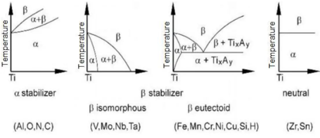
Usually Ti alloys are classified into three different groups α, β, α+β based on the effect of amount of the mixing elements added to the alloys, as shown in figure 2-3. These elements are categorised to be: (i) α stabilizer elements which increase the transition temperature of Ti, and (ii) β stabilizing elements that decrease the transition temperature. The majority of β stabilizing elements are considered to be body-centred cubic elements including Mo, V, Nb, Ta, Mn, Fe, Cr, Co, Ni, and Cu. However, some interstitial and substitutional elements like Al, Ga, Ge and Sn are employed as α stabilizing element.
Figure 2-3: Different alloying elements and their effect on titanium alloy phase (18)
Table 2-1 presents some Ti properties compared to other common metallic elements. Table 2-1: Titanium characteristics compared with other elements (18)
Ti Fe Ni Al
Melting Temperature ᵒC 1670 1538 1455 660
Allotropic Transformation Β 822C α γ 912C α - -
Crystal Structure bcc hex fcc bcc fcc fcc
E (GPa) at room temperature 115 215 200 72
Yield Stress level (MPa) 1000 1000 1000 500
Density (g/cm3) 4.5 7.9 8.9 2.7
Comparative Corrosion Resistance Very High Low Medium High
Comparative Reactivity with Oxygen Very High Low Low High
Comparative Price of Metal Very High Low High Medium
The different stabilising elements used in this study included Sn, Ta, Mo and Nb. These elements were selected based on their effect on phase transformation and
Literature Review
11
superelasticity of each alloy. The influence of these alloying elements on thermos-mechanical properties has seen some references in literature.
With regards to Sn, this has a significant effect on the superelasticity with increase in Sn content the super elasticity will decrease (21). Also transformation temperature decrease when the Sn content has increased (21,22). Figure (2-4) shows the effect of Sn content on the Ti-16Nb-(4-5) Sn alloys.
Figure 2-4:Effect of Sn content on transforamtion temperature (21)
As for each 1% Sn content increase in the range of 4-5%, the transformation temperature with decrease around 150K. In addition, Sn reduces the elastic modulus as it does not halt the formation of the β phase within the sample (23) as shown in figure (2-5).
Literature Review
12
Figure 2-5: Sn addition effect on elastic modulus and microhardness (23)
Increasing the Ta content has an effect on the phase structure of the binary Ti alloy (24). In that study, when Ta increased up to 60% the formed phase within the alloy was the β+ α’’ phase. Whereas if the Ta content increased above 60%, it showed only β phase present in the alloys. The phase structure for the Ti-Ta alloy was not recrystallized completely when Ta content percent increased to 70 and 80%. Table (2-2) shows the crystal structure and phase combination when Ta increased within the Ti alloy, reported by the study.
Table 2-2:Ta content effect on Ti alloys phase structure (24)
Ta content (%) Formed Phase Morphology
10-20 α’ Lamellar
30-50 α’’ Needle-like
60 β + α’’ Equiaxed β+ Needle-like α’’
70-80 β Equiaxed β+unrecrystallized structure
Kim.H.Y et al. (25) have found that if Ta content increased in the ternary alloy Ti-Nb-Ta by 1 at% the Ms decreased about 30K. As they increased Ta content within the range 0-8at%, the Ms temperature decreased with the increase of the Ta content as shown in figure (2-6). However, the strength of the alloys decreased with the addition of Ta up to 4% then increased again when the Ta content percent increased up to 8%.
Literature Review
13
Figure 2-6: Ta content added to Ti-22Nb-(0-8) Ta alloys (25)
The binary Ti-Mo phase structure has a sensitive respond to the addition of Mo: the α’ phase was the only phase with pure Ti while adding 3.2at% of Mo a small peak of α’’ phase was present (26). Increasing Mo content to 4.5% resulted in the phase detected in the alloy to be α’’ phase and if the Mo percent increased to 6 and 7% both β and ω phase were observed in the XRD profile. Table (2-3) summarizes the Mo content addition with the phase structure of the Ti alloys.
Table 2-3: Mo content effect on Ti alloys phase structure (26)
Mo content (%) Formed Phase Crystal structure
0 α’ Hexagonal 3.2 α’’ Orthorhombic 4.5 α’’+ ω Orthorhombic+ hcp 6 β + ω Bcc+ hcp 7 β + ω Bcc+ hcp 8-12 β Bcc
Besides that, the elastic modulus decreased with the addition of Mo content compared to pure Ti. When Mo was added within the range 0-12at% the highest elastic modulus reached was when Mo at 6% and the lowest when Mo at 8%, as shown in figure (2-7).
Literature Review
14
Figure 2-7: Effect of Mo addition on elastic modulus (26)
Decreasing the Nb content below 25.5 at% in the binary Ti-Nb alloys will increase the martensitic transformation temperature (Ms) higher than room temperature (25,27). During the cooling process the Ti-Nb alloys exhibit a martensitic transformation from β with bcc structure to α’’ phase with a C-centreed structure (27). Ping D.H et al. (28) have found in their study that quenching Ti-Nb alloys results in forming a martensitic α’ phase with a hcp structure with Nb content up to 12 wt.%. However, if Nb content increased beyond that value, the α’ phase would transform to orthorhombic α’’ phase. Bonisch M. et al. (29) have studied the phase transformation of seven different Ti-Nb alloys with Nb content in the range of 14 to 29 wt%. They found that alloys with <24 wt% Nb behave in the same way regardless of phase transformation at heating, as α phase transforms into β phase. While Ti-Nb alloys with >24 wt% Nb showed different transformation behaviour as α’’ phase transformed into unstable β phase. Furthermore, DSC results on cooling have shown that Ti-Nb alloys with Nb content >21 wt% have phase transformation from single β phase to α’’ phase. Figure (2-8) shows the DSC results for all Ti-Nb alloys on heating and cooling.
Literature Review
15
Figure 2-8: DSC results during heating and cooling (29)
2.3
Titanium –Based Alloys and Their Application as
Orthopaedic and Medical Devices
In general choosing a material for orthopaedic application raises several issues and points that are to be investigated. Important issues for biomedical application are: biocompatibility, adaptation to host tissue without rejection, as well as high wear resistance and anticorrosion features. For bio-medical application it is very important to find material with good mechanical properties (i.e. elastic modulus and strength) and β-Ti alloys are considered as promising alloys (25,30-32). Moreover, the nominated material should be easy to manipulate and fabricate to any shape required to replace different orthopaedic application with minimum cost. Lightweight and high stiffness and strength properties place Titanium (Ti) at the top of the orthopaedic material desirable materials list, since this element exhibits these two crucial properties. Alloys including Ti-6Al-4V and NiTi were used in orthopaedics applications widely in the past because of their behaviour with regards to mechanical properties and high corrosion resistance but scientists are worried of some elements such as Aluminium (Al), Vanadium (V) and Nickel (Ni) producing toxic ions and leaching them to the blood stream (21). Under these circumstances, new different Ti alloys found in the last few years have been adopted as orthopaedic implants. For example, Ti-Nb-Ta-Zr (33), Ti-Ti-Nb-Ta-Zr-Nb (34), Ti-Ti-Nb-Ta-Zr-Nb-Ta-Pd (35), Ti-Al-Nb and Ti-Al-Nb-Ta (36), Ti-Ni-Ta (37) and Ti-Sn-Nb (38) are present in orthopaedic applications as shown in table 2-4.
Literature Review
16
These Ti-based alloys are β-phase containing and are capable of reducing mechanical stiffness mismatch maintaining a good level of strength. In addition, their martensitic transformation temperature can be modified. This permits that the β-phase can be stabilised at temperature lower than the β transus.
Table 2-4: Titanium alloys for biomedical applications (1,33)
Alloys Composition Microstructure type
Pure Ti α Ti-6Al-4V ELI α+β Ti-6Al-4V α+β Ti-6Al-7Nb α+β Ti-5Al-2.5Fe α+β Ti-5Al-3Mo-4Zr α+β Ti-15Sn-4Nb-2Ta-0.2Pd α+β Ti-15Zr-4Nb-2Ta-0.2Pd α+β
Ti-13Nb-13Zr Near β (low modulus)
Ti-12Mo-6Zr-2Fe β (low modulus)
Ti-15Mo β (low modulus)
Ti-16Nb-10Hf β (low modulus)
Ti-15Mo-5Zr-3Al β (low modulus)
Ti-15Mo-2.8Nb-0.2Si-0.26O β (low modulus)
Ti-35Nb-7Zr-5Ta β (low modulus)
Ti-29Nb-13Ta-4.6Zr β (low modulus)
Ti-40Ta, Ti-50Ta β (high corrosion resistance)
2.4
Martensitic Phase Transformation
Phase transformation is the change from one phase or more within an alloy to convert to another phase or different phases. Instability within the system or alloy at its primary state is the main reason for transformation. In HCP titanium and titanium alloys, the bcc β phase can be transformed to α phase martensitically or by growth process through the effect of alloy combination and the heating/cooling process. In addition, atoms shear movement is required within crystalic phase to achieve perfect transformation of bcc into hcp inside a specific volume. Martensitic phase transition is named after a German scientist Dr Adolf Martens when he described a transformation from cubic phase to orthorhombic phase, via a solid-to-solid transformation (14). One explanation provided is through thermodynamic phase transformation, which depends on the Gibbs free energy function. When a constant temperature and constant
Literature Review
17
pressure are applied to develop a phase transformation in structure, then Gibbs free energy (g) informs about system stability.
Gibbs free energy equation
∆ = − 2-1
Where
Gm is the martensite phase GA is the austenite phase
Figure 2-9: Gibbs free energy for austenite and martensite (39)
In figure 2-9, martensite start temperature (Ms), austenite start temperature (As), equilibrium temperature (T0) and temperature change (Ts) with the change in Gibbs free energy are shown for martensite-austenite and austenite-martensite. This equilibrium temperature is applied since pressure is specified but for other pressures a significant change in equilibrium temperature is considered.
Literature Review
18
Figure 2-10: Thermal phase transformation path (40)
Within a thermal phase transformation the Ti alloy usually is cooled during transformation from its final austenite phase reached then reheated to achieve its start temperature before transformation. This is, the sample is cooled to its martensite temperature then sample will start to transform until it will get stable on its new crystalic structure until it reach its final martensitic state. Then reheating sample in reverse, the samples austenite transformation start for certain range of temperature until it reach its final austenite temperature to recover its original crystalic structure as shown in figure 2-10 .
2.5
Manufacturing Techniques for Titanium and Titanium Based
Alloys
In this section two different techniques to process Ti and Ti-alloys are surveyed. These include powder metallurgy and arc melting.
2.5.1 Powder Metallurgy Technique (PM)
Powder metallurgy technique is manufacturing technique to fabricate a material from elemental powders (41). A simple and high effective technique, powder metallurgy has been adopted for different materials production including metals, ceramics, polymers and composites. The PM process consists of three stages: powder mixing, powder compaction and sintering. The first stage involves mixing different elemental powders of the proposed composition and then loading the mix into a milling machine.
Literature Review
19
The mixture is milled for a specified duration and a certain milling speed until the mixing powder is homogenised. Table 2-5 shows different alloys prepared with ball milling. There are different millings factors considered including milling containers, speed, time, process control agent, milling temperature and ball-to-powder ratio. Figure 2-11 shows a schematic of the powders particles crushed during collision with milling balls.
Table 2-5:Different alloys prepared with ball milling
Alloy Mill type & brand PCA (SA or
EBS) Ratio Speed (rpm) Duration (h) References Ti-10Nb-10Zr Planetary ball milling (PM
400 Retsch) 1:2 100 4 (42)
Ti–16Sn–4Nb Planetary ball milling (PM
400 Retsch) 10:1 200 1, 10, 20 (43)
Ti–16Sn–4Nb Planetary ball milling (PM
400 Retsch) SA and EBS 1,2 , 3 % 10:1 200 5 (44)
Ti-50.8Ni UBM-4 mill 4:1 150 4 (45)
Ti-22Nb-6Zr Planetary ball milling 10:1 100 16 (46)
Ti-Mo Planetary ball mill 10:1 60 3 (47)
Ti–46.5Al– 4.0(Cr,Nb,Ta,B)
Fritsch P5 ball mill
Cr- Steel Vial or WC vial
Cyclohexane,
SA and TiH2 2.5:1 to 16:1 228 (S)25, (WC)10 (48)
Ti–10Si–5B and Ti–20Si–10B
planetary Fritsch P-5 ball
mill 10:1 300 200 10, 21 (49)
Al-10.7 Ti High energy planetary ball
mill Methyl alcohol 238:10 80 (G) 60 (50)
FeTi High energy planetary ball
mill 13:1 150 (51)
Literature Review
20
The second stage is the compaction process of the mixture where the powder is pressed in a proper mould to a certain pressure to compress all particles together producing green bodies (compacted powder without heat treatment). Finally the sintering stage is where particles bond to each other due to the heating effect. This explains why axial compaction of powder before sintering stage improves the strength of green products by increasing particles’ contact areas. On the other hand, sintering increases density and strength and helps manufacturing a very low porosity product. There could be a final heat treatment stage to further homogenise the alloys.
Powder metallurgy technique is considered most preferable technique to produce Ti and Ti-alloys due to low production cost and capability to fabricate new alloys with more control on microstructure compared to conventional techniques.
2.5.2 Arc-Melting
For a few decades arc-melting methods have been used as one of different fabrication techniques used in metals industry such as titanium and titanium alloys. The arc-melting process is carried out under a vacuum or inert atmosphere as it is very important to prevent reaction between the metal and oxygen or nitrogen atoms. Since the electrode is the anode for this process, the water-cooled copper crucible is the cathode. The applied arc is created between the electrode and the crucible to melt the compacted metal. Then, the molten metal is formed on a copper crucible after arc is stopped and the metal is solidified. Repeating arc-melting process helps homogenising the fabricated ingots. J.I. Kim et al. used arc-melting method to fabricate Ti-22Nb-(2-8) Zr (at %) ingots (52). The ingots were then cold-rolled to plates with 0.5 mm in thickness and then the plates were cut using electro-discharge machine (EDM). Al-Zain et al. (53) has fabricated Ti-27Nb and Ti-Nb-Mo alloys with different composition using arc-melting technique in Ar atmosphere. The manufactured ingots were then homogenized followed by cold rolling. In addition, Ti-35Nb-5Ta-7Zr alloy was fabricated using arc-melting method under Ar atmosphere by X.M. Ma et al. (54). The ingots homogenised at 1273 K for 86.4 ks and then solution heat-treated. W. Emay et al. has used arc-melting method to manufacture Ti-24Nb ingots (55). The fabricated ingots were subjected to a homogenisation at 1223K for 73ks then water quenched. After that the quenched samples were rolled at room temperature with 95% reduction. Table 2-6 shows some alloys examples fabricated with arc-melting.
Literature Review
21
Table 2-6: Ti-alloys fabricated by arc-melting method
Alloy Alloying
Process
After process Cold
Rolling (CR) Heat-treatment References Ti-(12- 28)Nb-(0-4) Mo Ar arc-melting Method for 6 times Homogenized at 1273 K for 7.20ks (1000 C for 2 h) CR 98.5%, cut
using EDM 973K for 0.6 ks (700 C @ 10 mins) in Ar then quenched Water @ RT (32) Ti-35 Nb-4Sn Ar arc-melting Method (8.9 mm) Homogenized at 1423 K for 86.4ks (1150 C for 24 h) CR (1.4 mm-2
mm-3.3 mm) Solution treated in quartz tubes 1223 K @ 7.2 ks (950C for 2 h) quenched in Iced water
(56) NA Ti-20Zr-10Nb Ar arc-melting Method for 4 times sample w (1.5 kg)
Cut into 5mm thick sealed in quartz tube and Homogenized at 900C for 2h then quenched in water CR 80% reduce from 0.7% to 2.4 % per pass with velocity 25 mm/s
Heat treated in quartz tube 600, 700, 800C for 0.5 h. then water quenching. (57) Ti-xTa-xSn Ar arc-melting Method for 6 times
Sealed in quartz tube Homogenized at 1273 K for 7.20ks (1000 C for 2 h) CR 98%, specimen cut for different test using EDM
Solution treated in Ar-quartz tubes 1173 K @ 1.8 ks (900C for 0.5 h) quenched in water (58) Ti-35Nb-5Ta-7Zr Ar arc-melting Method Homogenized at 1273 K for 86.4ks (1000 C for 24 h) then solution treated at 1273 K for 7.2ks (1000 C for 2 h) then water quenched
Sample cut into pieces & some CR reduce 90% (54) Ti-24Nb-1Al Ar arc-melting Method
Sealed in quartz tube Homogenized at 1000C for 4.5h Hot rolling at 1000C reduces 90% final thick 0.7mm.
Sheet cut and solution
treated at 1000C for 1 h. (59) Ti-24Nb Cold crucible levitation melting method (CCLM)
Sealed in quartz tube Homogenized at 1223 K for 7.20ks (950 C for 2 h) CR 95% reduce & tensile sample prepared (70x3x0.7 mm)
Some in tubes & solution treated at 1173 K for3.6 s (900C for 1 h) quenched in water. Some sample annealed at 873 K &573K for0.6ks (600C&300C for 10 mints) then water quenching (55) Ti-(15-35) Nb Ar arc-melting Method
Sealed in quartz tube Homogenized at 1273 K for 7.20ks (1000 C for 2 h) CR 98.5%, cut using EDM, then mechanical polishing and chemical etching
Wrapped in Ti foils and quartz tubes @ 25 Torr partial pressure of high-purity Ar, then solution treated at 1173 K for 1.8ks (900C for 0.5 h) . Water quenching. (25) Ti-7.5Nb-4Mo-2Sn Ar arc-melting Method flipped 5 times CR 70% reduces then heat-treated at 700Cfor 0.5 h in Ar atmosphere then water quenching. (60) Ti- 27Nb,Ti- (24- 13)Nb-(1-4)Mo Ar arc-melting Method Homogenized at 1273 K for 7.20ks (1000 C for 2 h) CR 98.5%, then cut for different test using EDM 973K for 0.6 ks (700 C @ 10 mints) in Ar then quenched Water (53)
Literature Review
22
2.6
Manufacturing Techniques for Porous Ti and Ti-Alloys
In recent years market demands for porous metallic products have increased and this has created a high production rate of metallic foams for various applications. The manufacturing technique is considered one of the important factors that affect the mechanical properties of porous material, including stiffness. Several manufacturing techniques are adopted to produce scaffolds. Some of them are based on traditional methods and others are recent innovations that are currently under development. Some of these techniques were adopted from porous polymer production and some were developed specifically for porous metal production. In addition, there are different techniques used to characterise the type and amount of pores (including open and closed pores) in the samples. Figure 2-7 shows different groups of the manufacturing techniques of porous metals. The manufacture of porous Ti materials presents some difficulties due to the high melting temperature of Ti and its affinity for oxygen (61).
Few different techniques were selected amonge all manufacturing techinques as highlighted in figure 2-12, to compare between them include gas injection into the metal melt technique, powder metallurgy with space holder technique, replica technique for porous materials and additive manufacturing technique.
Literature Review
23
2.6.1 Gas Injection into the metal melt Technique
This is one of the first technique used to manufacture metal porous materials and was used for the first time to manufacture aluminium foams and aluminium alloys foams. In this technique, the molten metal (of a viscosity) is mixed with viscosity decreasing adjuvants (e.g. silicon carbide and aluminium oxide) (2). The melt is foamed by injecting the gas through rotating impellers or vibrating nozzles. The function of rotating impellers and vibration nozzles is to produce and control the gas bubbles in the melt. A high porosity can be reached (around 98%) and large volumes of foams with low density are achieved. One of the drawbacks of this technique is that foaming with direct injection can generate brittle foams due to the high reactivity of titanium with oxygen. In the case of Ti, a high melting temperature is required which makes it difficult to use in solid conditions (62).
2.6.2 Powder Metallurgy with Space-Holder
As for as this study is concerned, we will focus on powdered metal systems, which are the area that present more advantages when handling Ti. This is a well-known procedure for the manufacture of porous products consisting of steps including powder mixing and preparation, compaction of the mix (or moulding) and sintering of the green product at a temperature lower than melting point of mixed material. As already described in section 2.5.1. Wen et al. used titanium powder with particles size less than 45 µm and purity >99.9% to produce Ti foam (63). Ammonium hydrogen carbonate powder was used as space- holder with particles size 200-500 µm to produce pores with size 200-500 µm. The process to manufacture Ti foam consisted of mixing, pressing and heat-treating step as shown in figure 2-13. The titanium powder and space-holder powder were mixed to produce the green compact. Pressure of 100 MPa was applied to compress the powder. Then the green samples were heat-treated to remove the space-holder particles and produce Ti foam. Heat-treatment process consisted of two stages: first to remove the space-holder from the green samples heated at 200°C for 5 h. Then temperature increased to 1200°C for 2h for the sintering process. Different samples with various densities were produced.
Literature Review
24
Figure 2-13: Fabrication Process for Titanium foams (63)
Ti-6Al-4V foams are produced using magnesium powders as space holder by Ziya Esen (64) as shown in figure 2-14. The powdered alloy had particles size ranging from 45-250 µm with an average particle size of 107µm. Magnesium powder with particles size 300-1500 µm was used as space-holder. The green samples were compacted at various pressures (375, 510, 750, and 1125 MPa) in a double ended steel die. The produced green samples were then heated slowly to 1200 °C and sintered for 1 h at the same temperature under high purity argon gas. Different samples with porosity ranging 43-64% and containing both macro and micro pores due to different sizes of space-holder used were manufactured.
Figure 2-14: Foam containing macropores (64)
Wenjuan et al. have used powder metallurgy technique to manufacture porous titanium using a space-holder material (65). The size of titanium powder particles was in the range of 44-74 µm with an irregular shape. Carbamide particles in the size range of 200-600 µm were used as the space-holder material based on previous research (66). Firstly, a preparation step was needed to reduce the size range of carbamide from 0.17-1.19 mm to get 200-600 µm by dissolving the particles in solution of ethanol and
Literature Review
25
water. Then titanium powder was mixed with the binder before adding carbamide particles to improve the green strength of powder compact. A Ti powder and carbamide were mixed in a V type mixer for 1h. The mixture was then uniaxially pressed using a steel die of 10mm. Green samples were sintered in different stages (at 200°C for 3 h,350°C for 3 h, and 1250°C for 3 h) and then furnace cooled. Porous Ti samples were produced with porosity in the range of 55-75% with pores size in the range of 300-500 µm with a mean value of 410 µm. Ti-10Nb-10Zr porous alloys were fabricated using powder metallurgy and space-holder sintering method by Wang et al. (42,67). High purity elements of Ti, Nb, and Zr with particle size smaller than 45 µm were mixed together and blended in a planetary ball milling system for 4 h. The blended mixture was added with urea as space-holder with particles size in the range of 500-800 µm. The mixture of alloy powder and urea was compacted in a 50 ton hydraulic press to produce green samples. The sintering stage occurred under vacuum pressure of 10-4 and 10-5 Torr in two steps: first to remove the urea at 175 °C for 2h and second at 1200°C and held for 10 h to undergo sintering. Various porous Ti-10Nb-10Zr samples were produced with porosity in the range of 42% to 74% including both open pores and closed pores. The porous TiNbZr scaffolds presented higher strength than porous unalloyed Ti scaffolds and presented an excellent ductility.
Using powder metallurgy technique along with space holder helps controlling the pore characterization in easy way by manipulating space holder particles either their quantity or size as shown in figure 2-15. This technique is suitable to manufacture devices for a wide range of applications.
Literature Review
26
Figure 2-15: Statistical analysis of pore size and distribution (42)
Several space holders have been reported in literature with different porous metal alloying as shown in table 2-7. Ammonium carbonate (NH4HCO3) is widely used by many researchers. The removal and sintering process are performed together in two different stages firstly by removing the ammonium bicarbonate by heating samples up to 175 °C for 5 hours in dwelling time inside tube furnace.
Several space holder removal techniques are invented and the most common one either by dissolution in water or by applying thermal energy to remove the space holder. Using water is insufficient to remove a high percentage of ammonium bicarbonate and consumes a lot of time (68).
Table 2-7: Different space holders and their removal techniques
Space holder Reference
Magnesium (3,64)
Ammonium bicarbonate (NH4HCO3) (40) (70)(71)(11)
Carbamide (Urea) (9,12,16,66,72) (66)
Paraformaldehyde (polyoxymethylene) (73)
Polymethyl methacrylate (PMMA) (74)
NaCl powders (75)
Yuan et al. fabricated Ti-Ni alloys using hot isostatic pressing and conventional sintering and then apply heat-treatment including aging at 450°C in a tube furnace
Literature Review
27
protected with high purity argon gas for 0.5 h and then iced-water quenching (76). After conducting different tests and analysis including optical micrograph as shown in figure 2-16 it shows the samples produced by CS have irregular and connected pores and that prove the effect of the high pressure on pore characterization compared to capsule free hot isostatic pressing (CF-HIP). Beside that sample produced by CS shows high open pore ratio and small pore size.
Figure 2-16: Optical micrographs of cross section of porous TiNi SMAs fabricated by CF-HIP and (b) CS process (76)
Kockar et al. employed CS to produce TiNi alloys using spherical powder with magnesium as space holder cold pressed at 400 MPa and sintered at temperature of 1100°C (77). After sintering samples were cooled down to 80°C directly inside the vertical tube furnace. Different pores levels and micro-pores were obtained during this process. Samples with 36% porosity exhibit 4.5 % recoverable strain under constant pressure of 100 and 25 MPa while the recoverable strain percentage decrease to 3.3% when porosity increased to 55 and 60% under lower constant stress around 50 MPa as shown in figure 2-17.
Literature Review
28
Ti-51Ni alloys were fabricated by self-propagating high temperature synthesis (SHS) with porosity of 52% by Chung et al. (78). The powders of all elements were mixed and blended in a ball-milling machine for 12 h. Then the green sample was produced by compressing the powder 50-100 MPa. XRD was used to analyse the phase transformation behaviour of produced TiNi alloys after applying annealing in a solution at 1050°C for 4 h and then aging at 500°C for 1 h. The achieved porosity was 52.8% with pores size range from 200-500 µm and open porosity ratio around 72 % and that explains the connectivity of the samples pores. In addition, the transformation temperature of produced alloys has a value around the human body temperature and a compressive strength to 500 MPa as shown in figure 2-18 to be used for heavy lead hard tissue implants. The obtainable Young’s modulus is near the value of human bones with 5.82 GPa.
Figure 2-18: Compressive stress-strain curve (78)
Brailovski et al. fabricated Ti-22Nb-5Zr alloys employing vacuum and arc-melting method apply cold rolling to reduce the thickness of ingots to 30-85% (8). Firstly, the obtained ingots were atomized to make them a powder form. Then the green sample was manufactured to have a porosity of 46%. Heat-treatment including annealing at 450°C and 600°C for 1 h and quenching was applied after annealing for the foam specimens. The increase of annealing temperature decreased Young modulus value from 8-12 GPa in sintering to 5-7 GPa in annealing as shown in figure 2-19. Besides that, the stiffness is reduced when a higher annealing temperature is achieved.
Literature Review
29
Figure 2-19: Compression testing of Ti-Nb-Zr (a) as sintered (b) annealed at 450 °C (c) annealed at 600 °C(8)
A compilation of more examples of porosity-induced materials can be found in table 2-8.
Literature Review
30
Table 2-8: Different Ti-alloys with different heat-treatment
Alloy
Material Porosity (%) Size(µm) Pores Preparation Process Heat-treatment before testing Test Procedures stress (MPa) Constant Superelasticity behaviour Pores Formation Ti-49.2Ni
(76)
Dense NA Casting
method The compression tests at (26 ◦C). The strain rate is 3.33×10⁻³ s−1.
Scanning electron microscope was used to examine the fracture surface
500 Completed super elasticity at room temperature Maximum recoverable strain of 4%. NA 27 50-200 Hot isostatic pressing (HIP)
50 Spherical pores & large
size less open pores
43 <100 Conventional
sintering (CS) Specimens were aged at 450 ◦C for 0.5 h before compression testing, then ice-water quenched
Irregular and very good connected pores more open pores
Ti-50.6Ni (77)
36 250-600 Conventional
sintering (CS) Sintered compacts are cooled directly down to 80◦C in the cold zone of the vertical furnace.
The isobaric cooling–heating experiments with
incremental stress level of 25 MPa and constant rate 10_C/min
100-125 High recoverable strain up
to 4.5% Pores percentage was higher than space holder amount (30, 50, and 60) 55 50 3.3 % 60 50 3.6% Ti-51Ni (78) 52.8 200-500 Self-propagating high temperature synthesis (SHS) Phase transformation behaviour of TiNi SMA analysed after solution annealing at 1050 C for 4 h and aging at 500 C for 1 h
compressive samples were cut in a size of
about 6 mm in width, 5 mm in thickness and 15 mm in height at constant rate of 0.1 mm/min
500 The ultimate compressive strain of the specimen is 6.2%
The isotropic pore structure most pores are three-dimensionally interconnected Ti-20.8Nb-5.5Zr (8) 46 136- 561 Vacuum arc remelting & Powder metallurgy process Encapsulated in Ar-filled quartz tubes and annealed open air at 450◦C and 600◦C (1h) subsequent water quenching.
X-ray analysis (a) tensile testing, (0.5%) (b) three-point bending (1.2%) and (c) compression testing (4, 8 & 20%). Monotonous cycling (maximum 10 cycles)
Influence of the post-sintering thermal treatment on the onset stress and apparent Young’s modulus and manifest linear superelastic behaviour
Pore size and distribution has no evident dependence on thermal treatment Cu–11.7Al– 2.49Mn (79) 67.5, 52.6 and 73.1, 400 Sintering– dissolution process by using NaCl particulates as space holders Solution and
quench treatments after holding at 850 °C for 1 h
Uniaxial compressive tests at a strain rate of 10−2 s−1 at room temperature, Optical microscopy and (SEM) were done.
Non-martensite of β phase during slow cooling, After the solution and quench martensite is the main phase in matrix, before quenching brittle & after is ductile. Uniformly distributed and interconne