http://www.sciencepublishinggroup.com/j/wcmc doi: 10.11648/j.wcmc.20190701.14
ISSN: 2330-1007 (Print); ISSN: 2330-1015 (Online)
Optimal Placement of UAV for Coverage Maximization with
Minimum Path Loss
Asad Mahmood
1, *, Saad Salman Khan
1, Muhammad Qamar Usman
1, *,
Shahzada Zamin Abbas Khan
1, Muhammad Salman Sarfaraz
1, Khurram Shahzad
1, *,
Nayab Saddique
2, *1
Department of Electrical and Computer Engineering, Comsats University Islamabad, Islamabad, Pakistan
2
Department of Electrical Engineering, Capital University of Science and Technology, Islamabad, Pakistan
Email address:
*
Corresponding author
To cite this article:
Asad Mahmood, Saad Salman Khan, Muhammad Qamar Usman, Shahzada Zamin Abbas Khan, Muhammad Salman Sarfaraz, Khurram Shahzad Nayab Saddique. Optimal Placement of UAV for Coverage Maximization with Minimum Path Loss. International Journal of Wireless Communications and Mobile Computing. Vol. 7, No. 1, 2019, pp. 27-31. doi: 10.11648/j.wcmc.20190701.14
Received: March 13, 2019; Accepted: May 8, 2019; Published: May 31, 2019
Abstract:
Unmanned Aerial Vehicle (UAV) act as a flying Base Station (BS) is ascertained an auspicious way to cater the problems of system coverage and capacity. There are some constraints that must be considered to set out a UAV in place of a Base Station (BS). The accessibility of a reliable wireless backhaul link is one of the aforementioned limits and it is considered in this work. The paper explores diverse sort of wireless backhauls that delivers unlike data rates, and their impact on the served users. We present a dual model network0centric’s and user0centric’s and the optimum 3 dimensional assignment of a UAV is calculated for each model. We then maximized the quantity of attended consumers and sum rates for both models. Furthermore it is preferred to lessen the UAV movements which results in increasing flying time & decreases channel variants and the performance of the network is analyzed in correspondence to the user’s translations.Keywords:
User Maximization, NOMAD, Backhaul, UAV’s1. Introduction
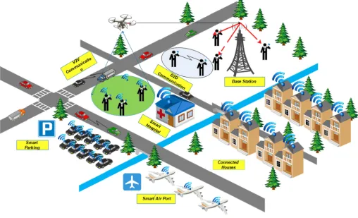
The use of the UAV’s has recently attracted considerable attention in the wireless cellular network as an encouraging way out to increase the coverage or capacity of the zone within the 5th generation network. UAV’s can help BS land networks in given that h coverage with high data rate every time besides where there is an inordinate need, particularly in the event that these permissions occur in a slightly challenging to envisage way [1]. Because of the rapid use of UAV’s, they also deal with momentary protection issues in isolated zones, or when land-based infrastructure is smashed by natural disasters. “Figure 1” is an illustration outline speaking to a few instances of automaton BS use in future systems. As per available in this “figure 1", UAV's can help terrestrial network to infuse capability and anticipate
placement of drone BS is reflected imperative issues to enterprise and appliance Het-Nets networks permitted for drone BS. the creators locate the number of UAV's to be minimize, 3-D positioning to accommodate a number of clients with high rate requirements via an evolutionary algorithm [1]. They discover that in densely populated areas, the UAV’s reduces its height to cause less annoyance to remote users who have not been delivered, and in low density areas, its height increases to accommodate more areas to provide more operators. author searches for 3-D UAV’s positioning for users maximization protected by statistical methods[5]. the bolted communication of possible interface link (LoS) between the air and the receiver is established and obtained by the analysis approach to the optimal height for radio coverage maximization [6]. optimum height of the UAV’s BS to attains the mandatory coverage with the low power transmission available [7]. It similarity use two UAV’s for coverage maximization in the absence of interference for front haul link. incorporate likelihood that Downlink inclusion in UAV's BS results height too receiving antenna gain, and after that find optimal location of UAV's BS for coverage maximization After all recent research, the remote
backhaul between UAV's and the core system isn't viewed as a constraining factor in the designing and application of UAV's that permits HetNets [8-12]. The main difference between a ground base station and a UAV’s base station is that the latter has an important limitation on the backlink. A ground base station typically has a static or remote backhaul remote association and can offer commonly high information rates to a focal system. An UAV's BS, then again, must have a Wireless connection for Backhaul; accordingly, the pinnacle rate that an UAV's BS can hold is restricted and can diminish drastically because of harsh climate, particularly if the connection depends on FSO or Mm Wave innovation. Subsequently, an essential issue, which the best of our insight has yet to be addressed, will be to reflect the impediments and fundamentals backhaul wireless interface by way of limitation when designing and conveying UAV's BS in future 5thG+ systems. We investigated robustness of UAV’s BS placement and studied the extent to which user movements can mark the planned optimum solution. Remaining paper formulated as Section 2 contain System model section 3 contain results and discussion whereas section 4 contains conclusion.
Figure 1. System Model.
2. System Model
There are confined representations of research associated with the air-to-ground Path Loss Model. That review demonstrates that there are two primary proliferation categories, comparing to receiver with LoS associations and
180 ( (( ) )) 1 1 e PLos β πθ α
α
− − =+ (1)
where α and β are continual quantities relying upon the environmental conditions where tilt angle (θ) equivalent to tan-1(h/r), altitude of an UAV's BS and its separation from receiving devices is represented by h and r, respectively without considering impact of shadowing; then again, the regular Path loss is exhibited in a probabilistic way as mention in [9].
(db) 20 log(4 f d/ c)c P(Los) LOS P(Los) NLOS
PL = π + η + η (2)
Free Space Path Loss (FSPL) as a primary term as indicated by Frii's equations. Variable fc (carrier frequency), c represents the speediness of light, d represents the separation among the UAVs, as appeared in the equation, ηLoS and ηNLoS are the normative sufferers for LOS and NLOS connections individually, whose qualities be dependent on upon the particular condition.
2 2
d= h +r (3)
( ) 1 ( )
P NLos = −P Los (4)
We expect that a region at that time being covered by terrestrial network, yet because transient increment in quantity of clients or their essential data-rates, some of them can't be served by the ground base stations because of absence of assets, for example, band-width. We recommend incorporating UAV's BS into the current versatile framework to give inclusion to these clients. The choice which clients to serve in the system relies upon the methodology chosen means either network centric or user centric. Clients are conventional to run distinctive bids with various execution requirements. Then total band-width of UAV's base station is the restricting elements in our framework.
1
. N
i i
r I R
=
≤
∑
(5)Where number of users, peak backhaul rate, data rate for each user is represented by N, R as presented in Equation 5 and ri respectively. Ii binary numbers donate number of selected users as indicated is Equation 6
{
1 f user is served by UAV 0 Other wiseI
=
i (6)Bandwidth requirement is another important factor that need to be address as mention in Equation 7 bi signifies the band-width essential by the ith user to fulfill its requirements and is equal to ri/ ζi where ζi = log2 (1 + γi) where γi
represented the S-N-R of ith user.
1
. N
i i i
b I B
=
≤
∑
(7)Likewise, we expect clients are range of the UAV's Base station if its Q-o-S prerequisite is fulfilled. It very well figured as in Equation 8
1
. max
N
i i
Ii PL PL
=
≤
∑
(8)Here PLi is the path loss of individual users PLmax is the maximum path loss. At last, our MINLP problem expressed as:
1:
x z Imax y
∑
αi.Ii∀i= N (9) Such that 1 . N i i ir I R
=
≤
∑
(10)1
. N
i i i
b I B
=
≤
∑
(11)max -1
N
i i
PL ≤PL
∑
(12)min uav max
X ≤x ≤X (13)
min uav max
Y ≤ y ≤Y (14)
min uav max
Z ≤z ≤Z (15)
[0,1]
i i
I = ∀ (16)
Table 1. Parameter Table.
Parameter Value Parameter Value
Carrier fc 2 GHz PLmax 120 dB
Zmax 400 m B 15 MHz
Pt 5 Watt R 80 Mbps
a 9.61 b 0.16
nlos 1 dB nnlos 20dB
Where x uav, y uav and z uav are the 3rd dimensional locations of UAV’s. The factors xmin, xmax, ymin and ymax are filled in as the territorial boundary points are arranged and zmin and zmax are the baseline and the maximum height of the UAV’s base station. Our proposed problem is MINLP we use Matlab tool to solve using parameter as shown in “Table 1”.
3. Results and Discussion
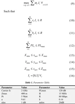
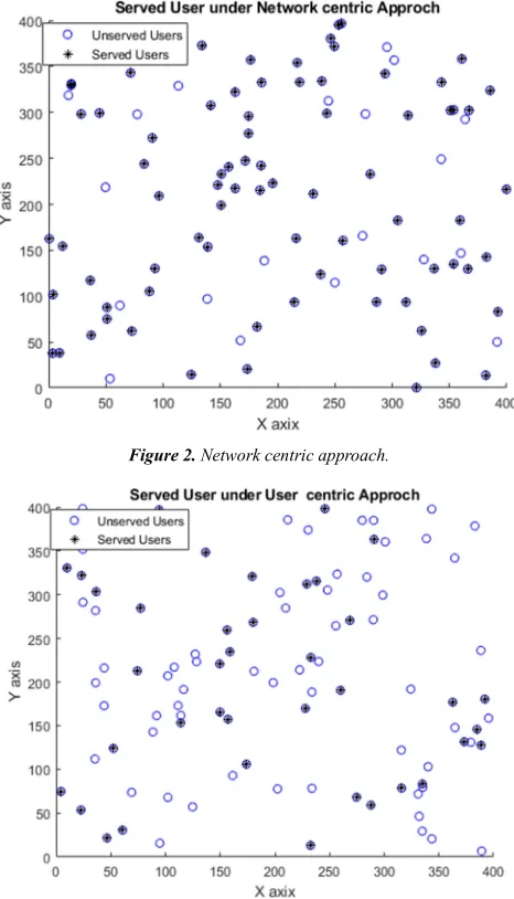
(zmax) to cover a wider region where network centric approaches served more number of user as compared to user centric approached. As seen on the behalf of network provide network centric approach better because it serve more number of user as compared to user centric approach, because they have to pay against spectrum usage.
Figure 2. Network centric approach.
Figure 3. User Centric approach.
The link can be allocated to the wireless unit within range. The user connection can be FSO or mm Wave between the core network and access. These connections can provide high data throughput, on the other hand, are extremely responsive to climatic surroundings; in foggy or harsh climates, data transfer rates can be significantly reduced [4].
Presently, in LTE, Wi-Fi, WiMAX and HSPA systems, fundamental invention used in remote network depends on the radio frequency microwave. Microwave can be driven very quickly with moderate minimum effort. With radio frequency connectors, the same spectrum is used in both the line and rear channel, causing interference and capacity of back-haul is affected. “Figure4” shows the relationship between the number of attended users and the peak values for
back-haul, using user and network centric approach. As shown in “Figure 4” the low connection speed can significantly reduce the number of users being served. By increasing the back-haul aptitude, the quantity of attendant customers increases. The rate of rise in the quantity of server consumers is slow in a user-centric’s tactic as shown in “Figure 4” while in a central network approach.
The steady decline in user focus is due to the statistic that in this scenario, top consumers are the first to be introduced, and when the bandwidth rises, uninteresting consumers receive the services, thereby increasing the number of users served. Now a network approach, slope is not fixed, as this is the first time that low-servicing users are introduced; only rare high-cost consumers receive the service0by0increasing bandwidth, and0the increase is reduced at each stage to increase bandwidth.
Figure 4. Comparative analysis.
Unmanned aircraft are constantly changing its radio channel, so need unpredictable interference control and asset allocation plans is required. Moreover, the progressive deployment of the UAB's BS consumes lots of energy to operate and reduces0flight time.
Unmanned aircraft are constantly changing its radio channel, so need unpredictable interference control and asset allocation plans is required. Moreover, the progressive deployment of the UAB's BS consumes lots of energy to operate and reduces0flight time. Thus, a UAV's base station flies to a preset place in addition does not necessarily have to show signs of a change in his place due to the movement of the client, it will retain vitality and reduce uncertainty. As shown in “Figure 5” under the network0centric approaches, relation between quantity of attended user and user movement.
Figure 6. Percentage of Disconnected users.
“Figure 6” represent that the quantity of attended consumers decrease but this decrease is negligible, whereas “figure” shown that this only small percentage of user disconnected as user movement increase while UAV’s remain its constant position.
4. Conclusions
In our research article, we investigate the optimum 3 Dimension placement of a UAV for a municipal region, with diverse user’s data rate necessities. Next, we adopt the limiting factors, backhaul rate and UAV’s bandwidth, for aforesaid models. The foremost model, network-centric, optimizes the sum of attended consumers irrespective of their data rates. On the contrary, the user0centric model optimizes the sum rate requirements. The presented results indicate that a slight fraction of the attended consumers would0be in0outage once the consumers move, that things to see the effectiveness of the suggested procedure beside the modest movement if users. In the future, we investigate further the performance of proposed algorithm and look for the needed
enhancements in various cases such as the network centric case, where focus is to serve maximum possible small BSs instead of giving priority to the ones demanding high data rate.
References
[1] R. I. Bor-yaliniz, A. El-keyi, and H. Yanikomeroglu, “Efficient 3-D Placement of an Aerial Base Station in Next Generation Cellular Networks,” 2016.
[2] M. Alzenad, M. Z. Shakir, H. Yanikomeroglu, and M. Alouini, “FSO-Based Vertical Backhaul / Fronthaul Framework for 5G + Wireless Networks,” no. January, pp. 218–224, 2018. [3] S. Chandrasekharan et al., “Designing and Implementing
Future Aerial Communication Networks,” no. May, pp. 26– 34, 2016.
[4] I. Bor-yaliniz and H. Yanikomeroglu, “The New Frontier in RAN Heterogeneity ,” no. November, pp. 48–55, 2016. [5] E. Kalantari, H. Yanikomeroglu, and A. Yongacoglu, “On the
Number and 3D Placement of Drone Base Stations in Wireless Cellular Networks,” 2016.
[6] A. Mahmood, M. Q. Usman, K. Shahzad, and N. Saddique, “Evolution of Optimal 3D placement of UAV with Minimum Transmit Power,” vol. 7, no. 1, pp. 13–18, 2019.
[7] D. Communications, “Connection Steering Mechanism between Mobile Networks for reliable UAV ’ s IoT Platform,” 2017.
[8] S. A. W. Shah, T. Khattab, M. Z. Shakir, and M. O. Hasna, “A Distributed Approach for Networked Flying Platform Association with Small Cells in 5G + Networks.”
[9] L. Sboui, S. Member, and H. Ghazzai, “Achievable Rates of UAV-Relayed Cooperative Cognitive Radio MIMO Systems,” vol. 5, 2017.
[10] K. Gomez et al., “Aerial Base Stations with Opportunistic Links for Next Generation Emergency Communications,” no. April, pp. 31–39, 2016.
[11] P. L. Mehta and R. Prasad, “Aerial-Heterogeneous Network : A Case Study Analysis on the Network Performance Under Heavy User,” 2017.
[12] J. Lu et al., “Beyond Empirical Models : Pattern Formation Driven Placement of UAV Base Stations,” pp. 1–30.
[13] P. Taylor, M. Yao, and M. Zhao, “Intelligent Automation & Soft Computing Cooperative Attack Strategy of Unmanned Aerial Vehicles in Adversarial Environment,” no. April 2014, pp. 37–41, 2013.