Communication
Freeform Perfusable Microfluidics Embedded in
Hydrogel Matrices
Gabriela Štumberger 1, Boštjan Vihar 1,*
1 IRNAS - Institute for development of advanced applied systems, Valvasorjeva 42, 2000 Maribor, Slovenia * Correspondence: [email protected]
Abstract: We report a modification of the freeform reversible embedding of suspended hydrogels (FRESH) 3D printing method for the fabrication of freeform perfusable microfluidics inside a hydrogel matrix. Xanthan gum is deposited into a CaCl2 infused gelatin slurry to form filaments, which are consequently rinsed to produce hollow channels. This provides a simple method for rapid prototyping of microfluidic devices based on biopolymers and potentially a new approach to the construction of vascular grafts for tissue engineering.
Keywords: Freeform, hydrogel, gelatin, microfluidics, FRESH, bioprinting, vascularization
1. Introduction
Due to the required high proximity of cells to blood vessels, the fabrication of vascular structures has enormous impact on the engineering of tissues and organs. However, the required resolution, structural integrity and simultaneous biocompatibility is yet to be achieved, thus, the fabrication of thick vascular tissues is still the main challenge to solve in tissue engineering[1-3]. Several approaches to solve this have already been made, including subtractive or additive methods, micro-patterning with photolithography, induced angiogenesis, etc. [2,4,5]. While existing techniques show a lot of promise, many challenges remain to be resolved. These include transfer from 2D to 3D structures, mechanical integrity of tissues with a high density of hollow tubes and shear stresses due to fluid flow, or resolution [2,4]. Kolesky et al. (2016) have successfully managed to create thick tissues with 3D vasculature, however, the process is limited in its geometry to an even mesh in a cuboid structure [6]. In this work, we propose a new approach on how to create freeform, perfusable channels embedded in a gelatin matrix, based on freeform reversible embedding of suspended hydrogels (FRESH) by Hinton et al., 2015 [7]. The FRESH method allows precise deposition of material inside a gelatin matrix (slurry), which offers support for the printed material and consequently allows the fabrication of almost any shape or form. The matrix is prepared by washing and blending gelatin granules, to produce a finely particulate slurry, such that the nozzle can move between the particles without disturbing the already deposited material. As the base is infused with Ca2+ ions, ion-polymerizing substances such as alginate are encapsulated and cross-linked directly upon deposition. After printing, the matrix is liquefied by heating and the printed structure can be liberated from the matrix [7]. The aim of this work was to adapt the above mentioned process to 3D print sacrificial material into the hydrogel matrix, which can be removed afterwards, producing a freeform channel structure.
2. Materials and Methods
2.1 Preparing the materials
The to be printed ‘vessel filament’ was prepared by dissolving 0.1g of xanthan-gum (Herbana d.o.o.) in 20ml of distilled water and stirring over night at room temperature. 75μl of Royal-Blue 4001 ink (Pelikan AG) were added to the liquid, to improve the visibility of the later printed filament. For the matrix, gelatin granules from porcine skin (Sigma-Aldrich) were ground using a coffee grinder for 10min and sifted through a mesh filter. Filters with 90, 140, 200 and 250μm pore sizes were tested
in the process. The obtained powder was used for further preparation of the matrix. 2g of the gelatin powder were soaked in a 50mM CaCl2 solution at room temperature and stirred for 1 min. The stirring was stopped and the soaked granules were let to set at the bottom of the container, then the supernatant was removed. Fresh CaCl2 solution was added and the process was repeated 2 more times, until the supernatant was completely clear. Air bubbles were removed from the solution in a desiccator under vacuum and the final supernatant was removed. The slurry was heated to 32°C and mixed in a 4:1 ratio with a 10% gelatin solution (in 100mM CaCl2 at 32°C) and transferred to the printing container. Excess liquid was removed by capillary imbibition using a paper towel.
2.2 Printing
G-codes were prepared manually from vectorized images of the target geometries. Printing was performed on the Vitaprint (irnas.eu/vitaprint) using PlanetCNC software with a feedrate of 500mm/min. As the nozzle, blunt-end G27 needles were used (inner diameter 0.21mm).
2.3 Curing and rinsing
After printing the filament and matrix were let to rest at room temperature for 30 minutes and transferred to 6°C overnight, for the matrix to cross-link completely. After this stage the structure could optionally be released from the mold and transferred to a handling surface for perfusion tests. The printed filament was rinsed by inserting blunt-end G21 needles into the matrix with the tip adjacently to the filament and manually injecting tap water through a syringe.
3. Results and discussion
This section may be divided by subheadings. It should provide a concise and precise description of the experimental results, their interpretation as well as the experimental conclusions that can be drawn.
3.1. Slurry parameters
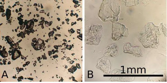
Due to grinding, the matrix particles were irregularly shaped, also, soaking increased particle size significantly, see Figure 1. Matrix particle size had a strong impact on structural stability of the matrix, as well as the channel shape fidelity and perfusability. Finer matrix particles resulted in better vessel resolution and a more consistent shape. On the other hand, larger particles showed greater structural stability of the finished prototypes.
Figure 1. Microscopic image of gelatin granules when dry (A) and soaked (B) in 100mM CaCl2 solution, compared to a reference bar of 1mm.
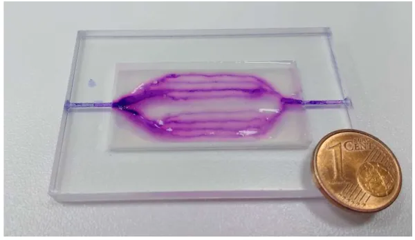
gelatin solution. In this constellation the fabricated vessels also showed good perfusability, figure 4, which could be sustained for several days without showing noticeable wear.
3.2. Geometry
Fabrication of hydrogel microfluidics was tested on three levels of fabrication intricacy: simple two-dimensional devices, simple three-dimensional devices and complex three-dimensional devices, all of which should fulfill the following requirements:
Repeatability
Even perfusion through all channels
Compatibility with various materials
3.2.1. Simple flat geometry
Samples were fabricated inside a 4mm thick acrylic plate with a 20x40mm well, which was filled with the gelatin slurry and lateral inlet/outlet channels with 1mm diameter for perfusion. A simple branched geometry was designed, making a single stroke at the thinnest branches, a double when two are added together, and so on. Before printing the microfluidics frame was placed on the printer and the starting position (x,y,z) = (0,0,0) was set for the nozzle tip to begin at the inlet position in the well.
3.2.2. Simple 3D geometry
A silicone mold was fabricated in the shape of a knee meniscus negative with inner dimensions of 55x35x12mm. The mold was filled with the slurry and 6 relatively shifted parallel arcs were written to emulate a vessel system of the “vascular meniscus zone”. After curing the structure was removed from the mold to test the stability of the gelatin structure in addition to the perfusability. The structure was transferred to a perfusion stage with two installed G21 needles piercing the meniscus model and connecting to the arc starting points on each side.
3.2.3. Complex 3D geometry
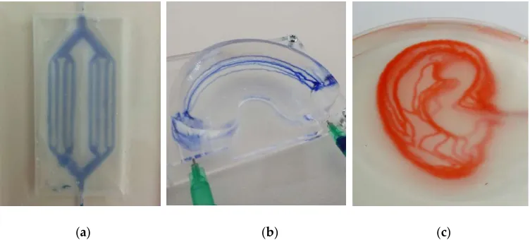
Finally a simplified vessel system of the human earlobe was modelled to test channels with complex geometries in 3D. The slurry was transferred into a PP petri dish inside which the channel system was fabricated and later perfused directly. Figure 2 shows the different complexity levels of the fabricated devices.
(a) (b) (c)
3.3. Perfusion
Perfusion of the microfluidic devices was tested using ink, which was injected manually with a syringe. The results are shown in Figure 3, as well as in the video in supplementary material.
(a) (b) (c)
Figure 3. Perfusion test of the earlobe-shaped channel system at three different stages by manual injection of ink (Pelikan AG). (a) after initial injection, (b) half full channel system, (c) full channel system.
3.4. Morphology and structure
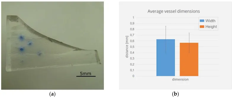
To obtain a homogeneous gelatin particle size and more precise control over printing resolution, granulated gelatin was finely ground and sifted. Decreasing grain size increases printing resolution of the vessels, thus channels with an average diameter of 0.6mm in a slurry made from 90-200micron sized particles showed a standard deviation in the x and y directions of 0.2mm, see Figure 4. Decreasing grain size however also reduces the stability of the final scaffold, thus meniscus structures made from particles with <90um size did not exhibit self-supporting stability when made with the described method.
(a) (b)
To increase the stability of the fabricated structures additional cross-linking would be an option. Studies have shown that gelatin scaffolds cross-linked with Glutaraldehyde and treated with sodium borohydride exhibit significantly increased stability, even in cell culture conditions (37°C, 5% CO2) and provide sufficient biocompatibility [8-9].
3.5. Alginate based structures
In addition, fabrication of hydrogel microfluidic devices can be performed using other biocompatible and biopolymers which can be translated into granulated form. In this work, the fabrication of Alginate based microfluidics was tested in simple flat geometry. Alginate beads were fabricated as described by Poncelet in 1992 [10]. The beads were washed, drained and resuspended with a 2% alginate solution in 100mM NaCl. As previously, excess liquid was removed by capillary imbibition. Cross-linking of the structure was performed by exchanging the Na+ ions with Ca2+ by covering the structure with a wetted paper-filter and exposed to a 50mM CaCl2 solution. The finished structure was perfusable, results are shown in Figure 5.
Figure 5. Alginate based microfluidic device in the shape of 2D branched structures.
This demonstrates that this method is also useful with other polymers, which allow the fabrication of beads, increasing the range of applications. The FRESH method was already shown to produce vascular structures where vessel walls were fabricated, which, however, sets a limit on the resolution and fabrication complexity and finer vessels (≤1mm) are difficult to manufacture in this manner. The proposed method allows fabricating vessels with a diameter comparable to the nozzle. Using gelatin grannules and G27 nozzles (0.21mm inner diameter, 0.41mm outer diameter), 0.6mm thick vessels could be produced, which should be optimized by improving matrix composition.
4. Conclusions
Supplementary Materials: The following are available online at
https://1drv.ms/f/s!AjDP44DcnnJYaQDlkEFSzyoUIM4 Video S1: vita_ear
Author Contributions: G. Š. carried out most of the laboratory work, preparing and testing the materials, optimizing composition and later on printability and the parameters of perfusion. B. V. designed the experiments and provided guidance and advice for the laboratory work.
Funding: This research was funded by the Shuttleworth Foundation through the Grant to Luka Mustafa at Institute IRNAS.
References
1. Rouwkema, J.; Rivron N.; van Blitterswijk, C. Vascularization in tissue engineering. Trends Biotechnol.2008, 26(8), 434-441, 10.1016/j.tibtech.2008.04.009.
2. Bae, H.; Puranik, A.; Gauvin, R.; Edalat, F.; Carrillo-Conde, B.; Peppas, N.; et al. Building Vascular Networks. Sci. Transl. Med.2012, 4(160), 160ps23-160ps23, 10.1126/scitranslmed.3003688.
3. Murphy, S.; Atala, A. 3D bioprinting of tissues and organs. Nat. Biotech. 2014, 32(8), 773-785, 10.1038/nbt.2958.
4. Hasan, A.; Paul, A.; Vrana, N.; Zhao, X.; Memic, A.; Hwang, Y.; et al. Microfluidic techniques for development of 3D vascularized tissue. Biomaterials. 2014,35(26), 7308-7325, 10.1016/j.biomaterials.2014.04.091.
5. Kolesky, D.; Truby, R.; Gladman, A.; Busbee, T.; Homan, K.; Lewis, J. 3D Bioprinting of Vascularized, Heterogeneous Cell-Laden Tissue Constructs. Adv. Mater., 2014, 26(19), 3124-3130, 10.1002/adma.201305506.
6. Kolesky, D.; Homan, K.; Skylar-Scott, M.; Lewis J. Three-dimensional bioprinting of thick vascularized tissues. PNAS.2016, 113(12), 3179-3184, 10.1073/pnas.1521342113.
7. Hinton, T.; Jallerat, Q.; Palchesko, R.; Park, J.; Grodzicki, M.; Shue, H.; et al. Three-dimensional printing of complex biological structures by freeform reversible embedding of suspended hydrogels. Sci. Adv., 2015, 1(9), e1500758-e1500758, 10.1126/sciadv.1500758.
8. Al-Rekabi, Z.; Pelling, A. Cross talk between matrix elasticity and mechanical force regulates myoblast traction dynamics. Phys Biol., 2013, 10(6), 066003. 10.1088/1478-3975/10/6/066003.
9. Hickey, R.; Pelling, A. The rotation of mouse myoblast nuclei is dependent on substrate elasticity. Cytoskeleton, 2017, 74(4), 184-194, 10.1002/cm.21357.